tow ACURA TL 1995 Service Repair Manual
[x] Cancel search | Manufacturer: ACURA, Model Year: 1995, Model line: TL, Model: ACURA TL 1995Pages: 1771, PDF Size: 62.49 MB
Page 12 of 1771
Towing
If the vehicle needs to be towed, call a professional tow-
ing service. Never tow the vehicle behind another vehi-
cle with just a rope or chain. It is very dangerous.
Emergency Towing
There are three popular methods of towing a vehicle:
Flat-bed Equipment — The operator loads the vehicle on
the back of a truck. This is the best way of transporting the
vehicle.
Wheel Lift Equipment — The tow truck uses two pivoting
arms that go under the tires (front or rear) and lifts them
off the ground. The other two wheels remain on the
ground.
Sling-type Equipment — The tow truck uses metal cables
with hooks on the ends. These hooks go around parts of
the frame or suspension and the cables lift that end of
the vehicle off the ground. The vehicle's suspension and
body can be seriously damaged if this method of towing
is attempted.
If the vehicle cannot be transported by flat-bed, it should
be towed with the front wheels off the ground. If due to
damage, the vehicle must be towed with the front
wheels on the ground, do the following:
Release the parking brake.
Start the engine.
Shift to position, then position.
Turn off the engine.
CAUTION:
Improper towing preparation will damage the trans-
mission. Follow the above procedure exactly. If you
cannot shift the transmission or start the engine, the
vehicle must be transported on a flat-bed.
It is best to tow the vehicle no farther than 50 miles
(80 km), and keep the speed below 35 mph (55 km/h).
Trying to lift or tow the vehicle by the bumpers will
cause serious damage. The bumpers are not designed
to support the vehicle's weight.
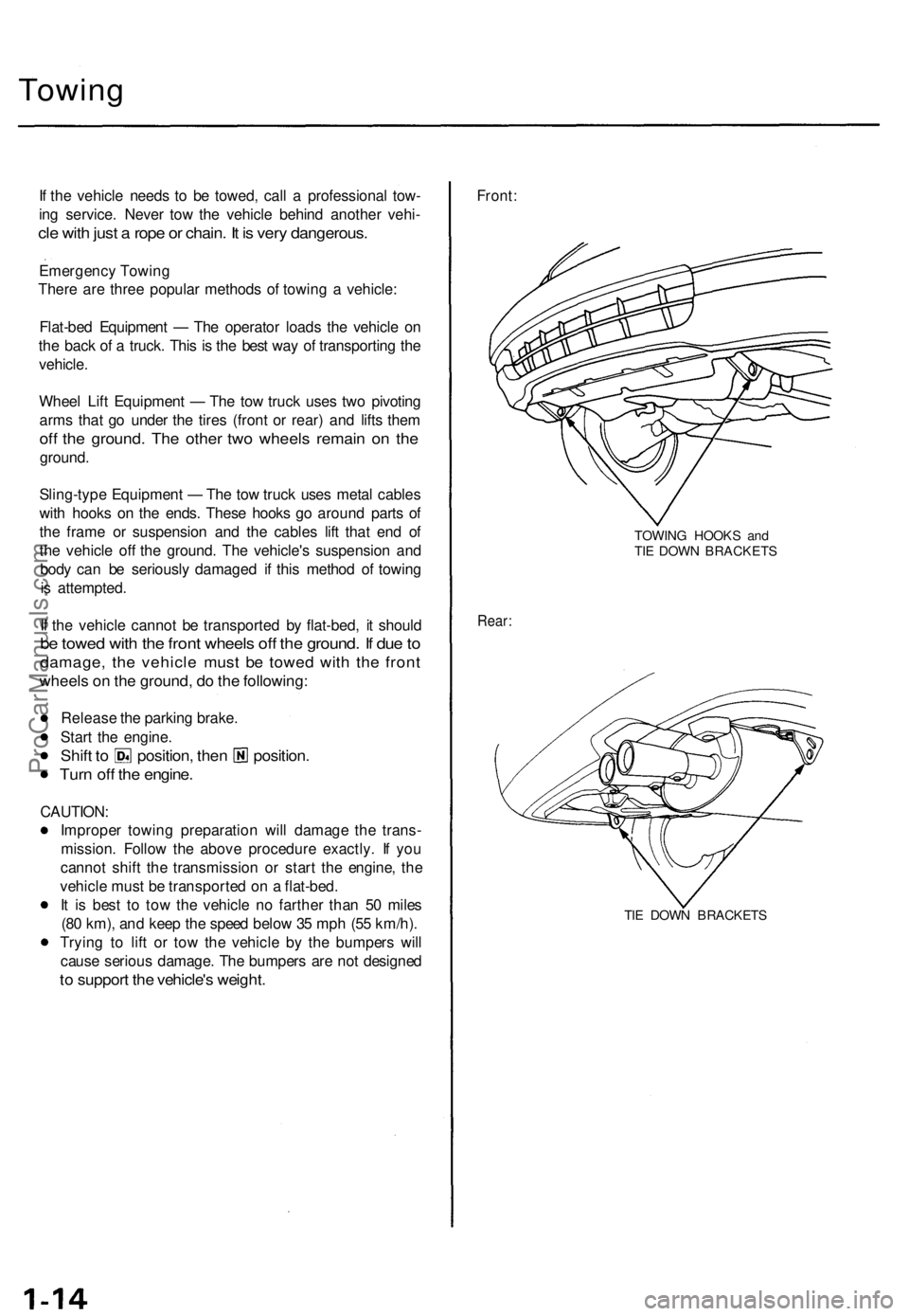
Front:
TOWING HOOKS and
TIE DOWN BRACKETS
Rear:
TIE DOWN BRACKETSProCarManuals.com
Page 33 of 1771
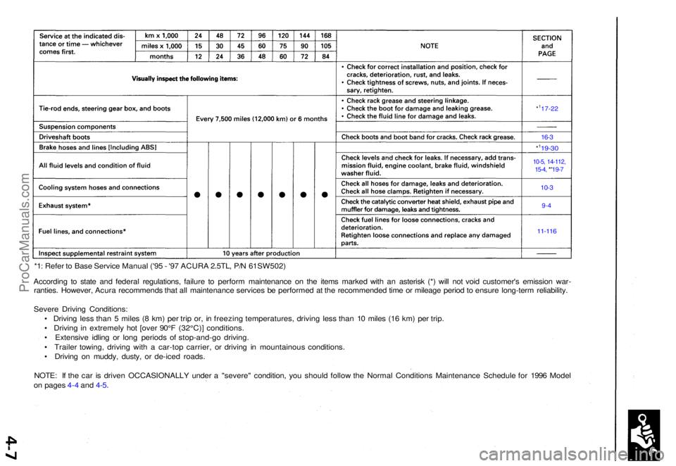
*1: Refe r t o Bas e Servic e Manua l ('9 5 - '9 7 ACUR A 2.5TL , P/ N 61SW502 )
Accordin g t o stat e an d federa l regulations , failur e t o perfor m maintenanc e o n th e item s marke d wit h a n asteris k (* ) wil l no t voi d customer' s emissio n war -
ranties . However , Acur a recommend s tha t al l maintenanc e service s b e performe d a t th e recommende d tim e o r mileag e perio d to ensur e long-ter m reliability .
Sever e Drivin g Conditions :
• Drivin g les s tha n 5 mile s ( 8 km ) pe r tri p or , i n freezin g temperatures , drivin g les s tha n 1 0 mile s (1 6 km ) pe r trip .
• Drivin g i n extremel y ho t [ove r 90° F (32°C) ] conditions .
• Extensiv e idlin g o r lon g period s o f stop-and-go driving.
• Traile r towing , drivin g wit h a car-to p carrier , o r drivin g i n mountainou s conditions .
• Drivin g o n muddy , dusty , o r de-ice d roads .
NOTE : I f th e ca r i s drive n OCCASIONALL Y unde r a "severe " condition , yo u shoul d follo w th e Norma l Condition s Maintenanc e Schedul e fo r 199 6 Mode l
o n page s 4- 4 an d 4-5 .
*117-2 2
16-3
*119-3 0
10-5, 14-112 ,
15-4 , *'19-7
10-3
9-4
11-11 6
ProCarManuals.com
Page 37 of 1771
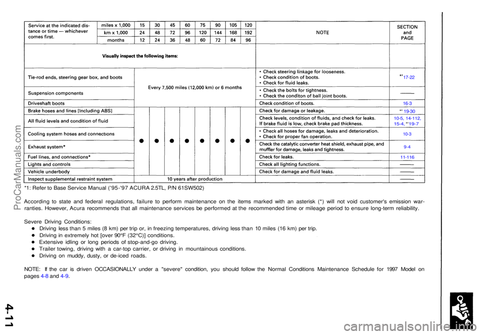
*1: Refe r t o Bas e Servic e Manua l ('95-'9 7 ACUR A 2.5TL , P/ N 61SW502 )
Accordin g t o stat e an d federa l regulations , failur e t o perfor m maintenanc e o n th e item s marke d wit h a n asteris k (* ) wil l no t voi d customer' s emissio n war -
ranties . However , Acur a recommend s tha t al l maintenanc e service s b e performe d a t th e recommende d tim e o r mileag e perio d t o ensur e long-ter m reliability .
Sever e Drivin g Conditions :
Drivin g les s tha n 5 mile s ( 8 km ) pe r tri p or , i n freezin g temperatures , drivin g les s tha n 1 0 miles (16 km ) pe r trip .
Drivin g in extremel y ho t [ove r 90° F (32°C) ] conditions .
Extensiv e idlin g o r lon g period s o f stop-and-g o driving .
Traile r towing , drivin g wit h a car-to p carrier , o r drivin g i n mountainou s conditions .
Drivin g o n muddy , dusty , o r de-ice d roads .
NOTE : I f th e ca r i s drive n OCCASIONALL Y unde r a "severe " condition , yo u shoul d follo w th e Norma l Condition s Maintenanc e Schedul e fo r 199 7 Mode l o n
page s 4- 8 an d 4-9 .
*' 17-2 2
16-3
*' 19-3 0
10-5, 14-112 ,15-4, *' 19- 7
10-3
9-4
11-11 6
ProCarManuals.com
Page 41 of 1771
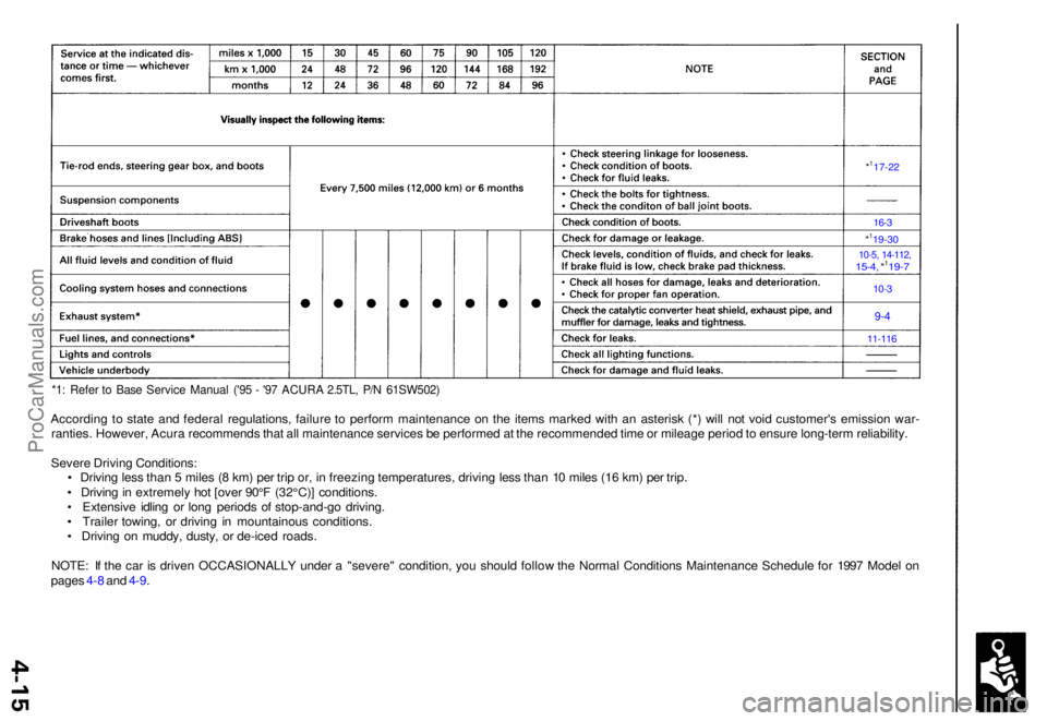
*1: Refe r t o Bas e Servic e Manua l ('9 5 - '9 7 ACUR A 2.5TL , P/ N 61SW502 )
According t o stat e an d federa l regulations , failur e t o perfor m maintenance on th e item s marke d wit h a n asteris k (* ) wil l no t voi d customer' s emissio n war -
ranties . However , Acur a recommend s tha t al l maintenanc e service s b e performe d a t th e recommende d tim e o r mileag e perio d to ensur e long-ter m reliability .
Sever e Drivin g Conditions :
• Drivin g les s tha n 5 mile s ( 8 km ) pe r tri p or , i n freezin g temperatures , drivin g les s tha n 1 0 mile s (1 6 km ) pe r trip .
• Drivin g in extremel y ho t [ove r 90° F (32°C) ] conditions .
• Extensiv e idlin g o r lon g period s o f stop-and-g o driving .
• Traile r towing , o r drivin g i n mountainou s conditions .
• Drivin g o n muddy , dusty , o r de-ice d roads .
NOTE : I f th e ca r i s drive n OCCASIONALL Y unde r a "severe " condition , yo u shoul d follo w th e Norma l Condition s Maintenanc e Schedul e fo r 199 7 Mode l o n
page s 4- 8 an d 4-9 .
*117-2 2
16-3
*119-3 0
10-5, 14-112 ,15-4, *119- 7
10-3
9-4
11-11 6
ProCarManuals.com
Page 76 of 1771
Cylinder Head s
Remova l (cont'd )
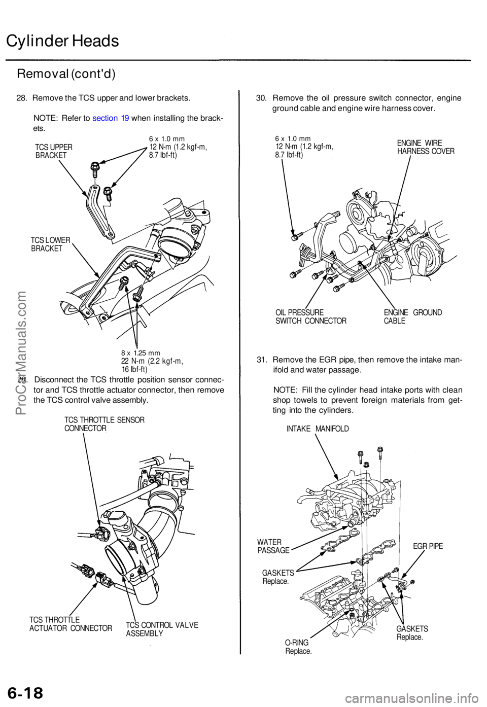
28. Remov e th e TC S uppe r an d lowe r brackets .
NOTE : Refe r t o sectio n 1 9 whe n installin g th e brack -
ets.
6 x 1. 0 m m12 N- m (1. 2 kgf-m ,
8. 7 Ibf-ft )
TC S LOWE R
BRACKE T
29.
8 x 1.2 5 mm22 N- m (2. 2 kgf-m ,
1 6 Ibf-ft )
Disconnec t th e TC S throttl e positio n senso r connec -
to r an d TC S throttl e actuato r connector , the n remov e
th e TC S contro l valv e assembly .
TCS THROTTL E SENSO R
CONNECTO R
TC S THROTTL E
ACTUATO R CONNECTO RTC
S CONTRO L VALV E
ASSEMBL Y
30. Remov e th e oi l pressur e switc h connector , engin e
groun d cabl e an d engin e wir e harnes s cover .
6 x 1. 0 m m12 N- m (1. 2 kgf-m ,
8. 7 Ibf-ft ) ENGIN
E WIR E
HARNES S COVE R
OI L PRESSUR E
SWITC H CONNECTO R ENGIN
E GROUN D
CABLE
31. Remov e th e EG R pipe , the n remov e th e intak e man -
ifol d an d wate r passage .
NOTE : Fil l th e cylinde r hea d intak e port s wit h clea n
sho p towel s t o preven t foreig n material s fro m get -
tin g int o th e cylinders .
INTAKE MANIFOL D
WATERPASSAG E
GASKETSReplace. EG
R PIP E
O-RIN G
Replace .
GASKET S
Replace .
TC
S UPPE R
BRACKE T
ProCarManuals.com
Page 82 of 1771
Camshaft
Inspection
NOTE:
Do not rotate the camshaft during inspection.
Remove the rocker arms and rocker shafts.
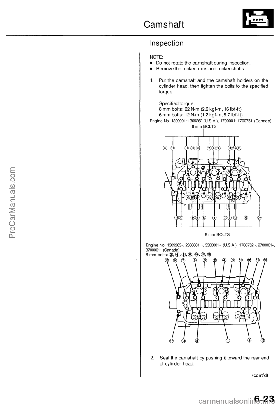
1. Put the camshaft and the camshaft holders on the
cylinder head, then tighten the bolts to the specified
torque.
Specified torque:
8 mm bolts: 22 N-m (2.2 kgf-m, 16 Ibf-ft)
6 mm bolts: 12 N-m (1.2 kgf-m, 8.7 Ibf-ft)
Engine No. 1300001~1309262 (U.S.A.), 1700001~1700751 (Canada):
6 mm BOLTS
8 mm BOLTS
Engine No. 1309263~, 2300001 ~, 3300001~ (U.S.A.), 1700752~, 2700001-
3700001~ (Canada):
8 mm bolts:
2. Seat the camshaft by pushing it toward the rear end
of cylinder head.ProCarManuals.com
Page 90 of 1771
Valve Guide s
Replacemen t
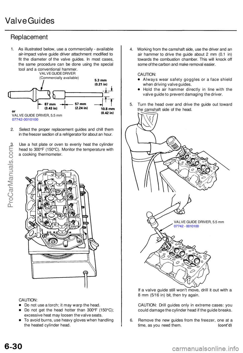
1. As illustrate d below , us e a commerciall y - availabl e
air-impac t valv e guid e drive r attachmen t modifie d t o
fit th e diameter of th e valv e guides . I n mos t cases ,
th e sam e procedur e ca n b e don e usin g th e specia l
too l an d a conventiona l hammer .
VALVE GUID E DRIVE R(Commerciall y available )
VALVE GUID E DRIVER , 5. 5 m m07742-001010 0
2. Selec t th e prope r replacemen t guide s an d chil l the m
i n th e freeze r sectio n o f a refrigerato r fo r abou t a n hour .
3 . Us e a ho t plat e o r ove n t o evenl y hea t th e cylinde r
hea d t o 300° F (150°C) . Monito r th e temperatur e wit h
a cookin g thermometer .
CAUTION :
D o no t us e a torch ; i t ma y war p th e head .
D o no t ge t th e hea d hotte r tha n 300° F (150°C) ;
excessiv e hea t ma y loose n th e valv e seats .
T o avoi d burns , us e heav y glove s whe n handlin g
th e heate d cylinde r head . 4
. Workin g fro m th e camshaf t side , us e th e drive r an d a n
ai r hamme r t o driv e th e guid e abou t 2 m m (0. 1 in )
toward s th e combustio n chamber . Thi s wil l knoc k of f
som e o f th e carbo n an d mak e remova l easier .
CAUTION :
Alway s wea r safet y goggle s o r a fac e shiel d
whe n drivin g valv e guides .
Hol d th e ai r hamme r directl y i n lin e wit h th e
valv e guid e to preven t damagin g th e driver .
5 . Tur n th e hea d ove r an d driv e th e guid e ou t towar d
th e camshaf t sid e o f th e head .
VALV E GUID E DRIVER , 5. 5 m m0774 2 - 001010 0
6.
If a valv e guid e stil l won' t move , dril l i t ou t wit h a
8 m m (5/1 6 in ) bit , the n tr y again .
CAUTION : Dril l guide s onl y in extrem e cases : yo u
coul d damag e th e cylinde r hea d if th e guid e breaks .
Remov e th e ne w guide s fro m th e freezer , on e a t a
time , a s yo u nee d them .
ProCarManuals.com
Page 93 of 1771
Valves, Valve Springs and Valve Seals
Installation Sequence
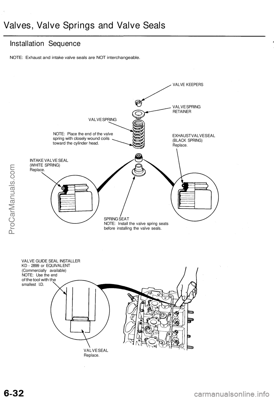
NOTE: Exhaust and intake valve seals are NOT interchangeable.
VALVE SPRING
NOTE: Place the end of the valve
spring with closely wound coils
toward the cylinder head.
INTAKE VALVE SEAL
(WHITE SPRING)
Replace.
VALVE KEEPERS
VALVE SPRING
RETAINER
EXHAUST VALVE SEAL
(BLACK SPRING)
Replace.
SPRING SEAT
NOTE: Install the valve spring seats
before installing the valve seals.
VALVE GUIDE SEAL INSTALLER
KD - 2899 or EQUIVALENT
(Commercially available)
NOTE: Use the end
of the tool with the
smallest I.D.
VALVE SEAL
Replace.ProCarManuals.com
Page 97 of 1771
Cylinder Heads
Installation (cont'd)
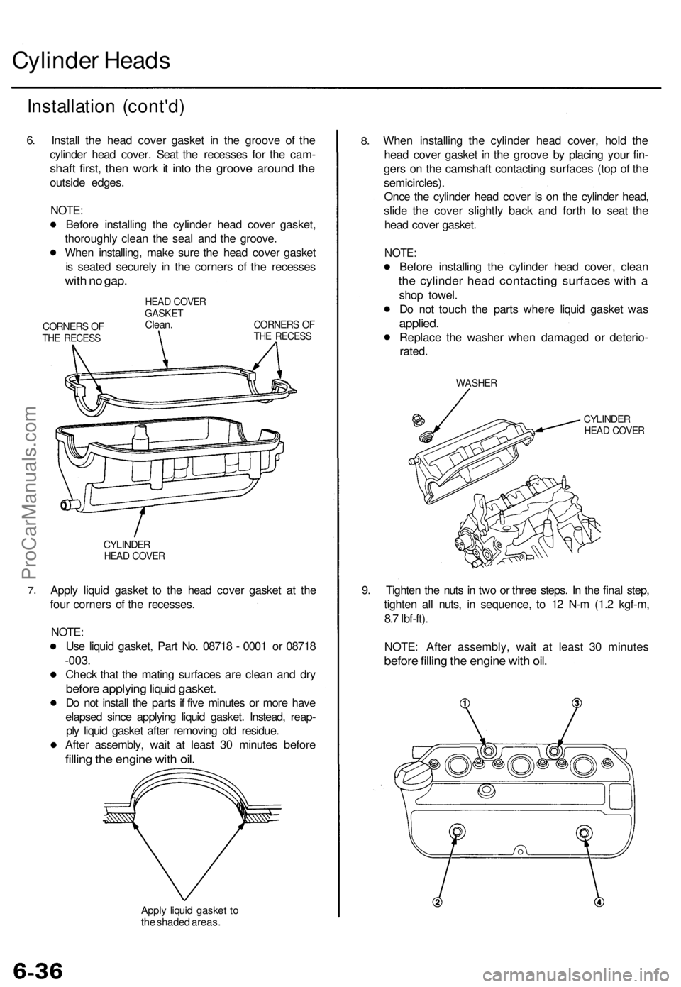
6. Install the head cover gasket in the groove of the
cylinder head cover. Seat the recesses for the cam-
shaft first, then work it into the groove around the
outside edges.
NOTE:
Before installing the cylinder head cover gasket,
thoroughly clean the seal and the groove.
When installing, make sure the head cover gasket
is seated securely in the corners of the recesses
with no gap.
CORNERS OF
THE RECESS
HEAD COVER
GASKET
Clean.
CORNERS OF
THE RECESS
7.
CYLINDER
HEAD COVER
Apply liquid gasket to the head cover gasket at the
four corners of the recesses.
NOTE:
Use liquid gasket, Part No. 08718 - 0001 or 08718
-003.
Check that the mating surfaces are clean and dry
before applying liquid gasket.
Do not install the parts if five minutes or more have
elapsed since applying liquid gasket. Instead, reap-
ply liquid gasket after removing old residue.
After assembly, wait at least 30 minutes before
filling the engine with oil.
Apply liquid gasket to
the shaded areas.
8.
When installing the cylinder head cover, hold the
head cover gasket in the groove by placing your fin-
gers on the camshaft contacting surfaces (top of the
semicircles).
Once the cylinder head cover is on the cylinder head,
slide the cover slightly back and forth to seat the
head cover gasket.
NOTE:
Before installing the cylinder head cover, clean
the cylinder head contacting surfaces with a
shop towel.
Do not touch the parts where liquid gasket was
applied.
Replace the washer when damaged or deterio-
rated.
WASHER
CYLINDER
HEAD COVER
9. Tighten the nuts in two or three steps. In the final step,
tighten all nuts, in sequence, to 12 N-m (1.2 kgf-m,
8.7 Ibf-ft).
NOTE: After assembly, wait at least 30 minutes
before filling the engine with oil.ProCarManuals.com
Page 103 of 1771
Drive Plat e Connectin
g Ro d an dCrankshaf t
Replacemen t En
d Pla y
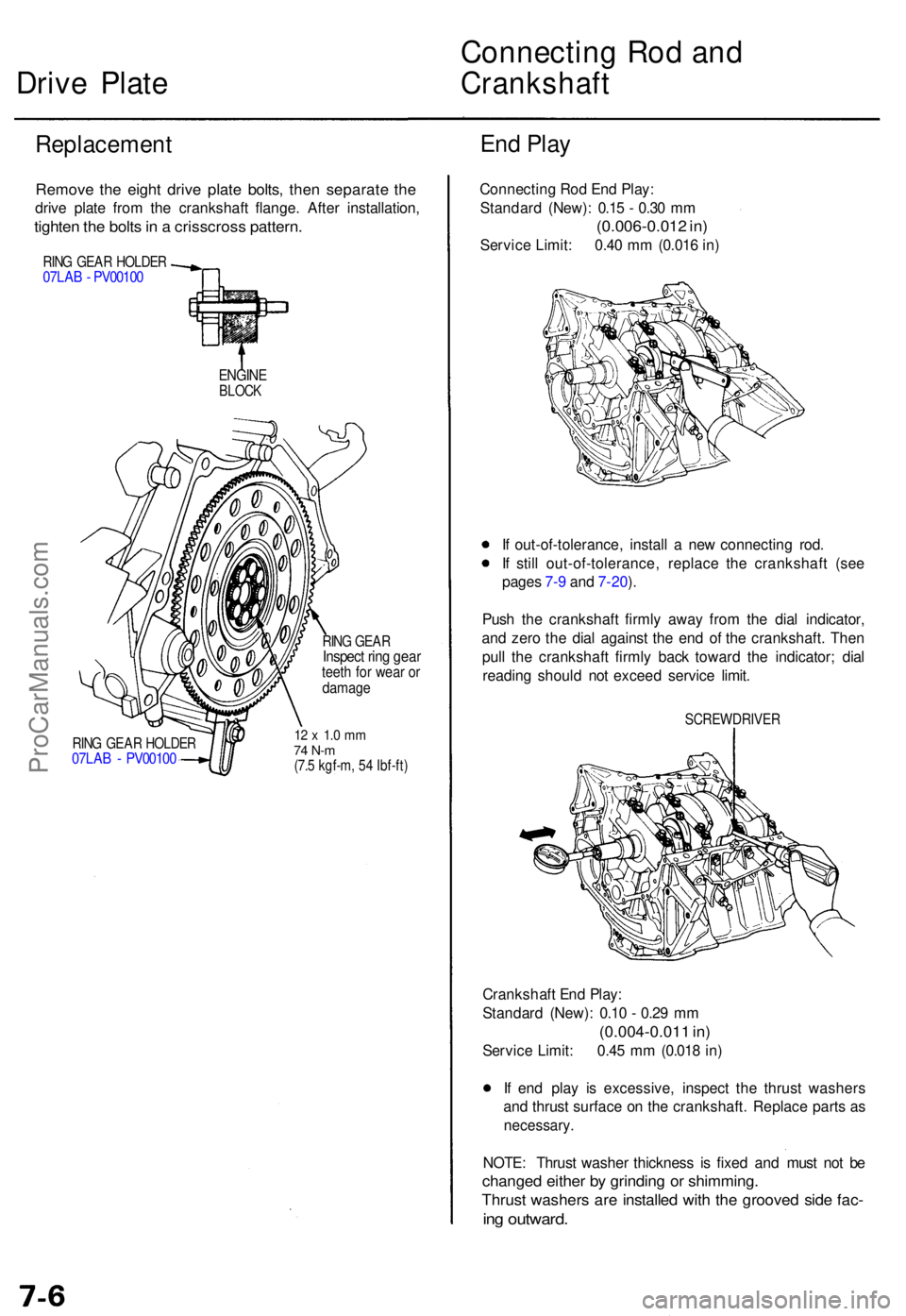
Remov e th e eigh t driv e plat e bolts , the n separat e th e
driv e plat e fro m th e crankshaf t flange . Afte r installation ,
tighten th e bolt s in a crisscros s pattern .
RING GEA R HOLDE R07LAB - PV0010 0
ENGINEBLOCK
RING GEA R HOLDE R07LAB - PV0010 0
RING GEA RInspec t rin g gea rteeth fo r wea r o rdamag e
12 x 1. 0 m m74 N- m(7.5 kgf-m , 5 4 Ibf-ft )
Connectin g Ro d En d Play :
Standar d (New) : 0.1 5 - 0.3 0 m m
(0.006-0.01 2 in )
Servic e Limit : 0.4 0 m m (0.01 6 in )
I f out-of-tolerance , instal l a ne w connectin g rod .
I f stil l out-of-tolerance , replac e th e crankshaf t (se e
page s 7- 9 an d 7-20 ).
Pus h th e crankshaf t firml y awa y fro m th e dia l indicator ,
an d zer o th e dia l agains t th e en d o f th e crankshaft . The n
pul l th e crankshaf t firml y bac k towar d th e indicator ; dia l
readin g shoul d no t excee d servic e limit .
SCREWDRIVE R
Crankshaft En d Play :
Standar d (New) : 0.1 0 - 0.2 9 m m
(0.004-0.01 1 in )
Servic e Limit : 0.4 5 m m (0.01 8 in )
I f en d pla y i s excessive , inspec t th e thrus t washer s
an d thrus t surfac e o n th e crankshaft . Replac e part s a s
necessary .
NOTE: Thrus t washe r thicknes s i s fixe d an d mus t no t b e
change d eithe r b y grindin g o r shimming .
Thrust washer s ar e installe d wit h th e groove d sid e fac -
ing outward .
ProCarManuals.com