tires ACURA TL 1995 Service Repair Manual
[x] Cancel search | Manufacturer: ACURA, Model Year: 1995, Model line: TL, Model: ACURA TL 1995Pages: 1771, PDF Size: 62.49 MB
Page 12 of 1771
Towing
If the vehicle needs to be towed, call a professional tow-
ing service. Never tow the vehicle behind another vehi-
cle with just a rope or chain. It is very dangerous.
Emergency Towing
There are three popular methods of towing a vehicle:
Flat-bed Equipment — The operator loads the vehicle on
the back of a truck. This is the best way of transporting the
vehicle.
Wheel Lift Equipment — The tow truck uses two pivoting
arms that go under the tires (front or rear) and lifts them
off the ground. The other two wheels remain on the
ground.
Sling-type Equipment — The tow truck uses metal cables
with hooks on the ends. These hooks go around parts of
the frame or suspension and the cables lift that end of
the vehicle off the ground. The vehicle's suspension and
body can be seriously damaged if this method of towing
is attempted.
If the vehicle cannot be transported by flat-bed, it should
be towed with the front wheels off the ground. If due to
damage, the vehicle must be towed with the front
wheels on the ground, do the following:
Release the parking brake.
Start the engine.
Shift to position, then position.
Turn off the engine.
CAUTION:
Improper towing preparation will damage the trans-
mission. Follow the above procedure exactly. If you
cannot shift the transmission or start the engine, the
vehicle must be transported on a flat-bed.
It is best to tow the vehicle no farther than 50 miles
(80 km), and keep the speed below 35 mph (55 km/h).
Trying to lift or tow the vehicle by the bumpers will
cause serious damage. The bumpers are not designed
to support the vehicle's weight.
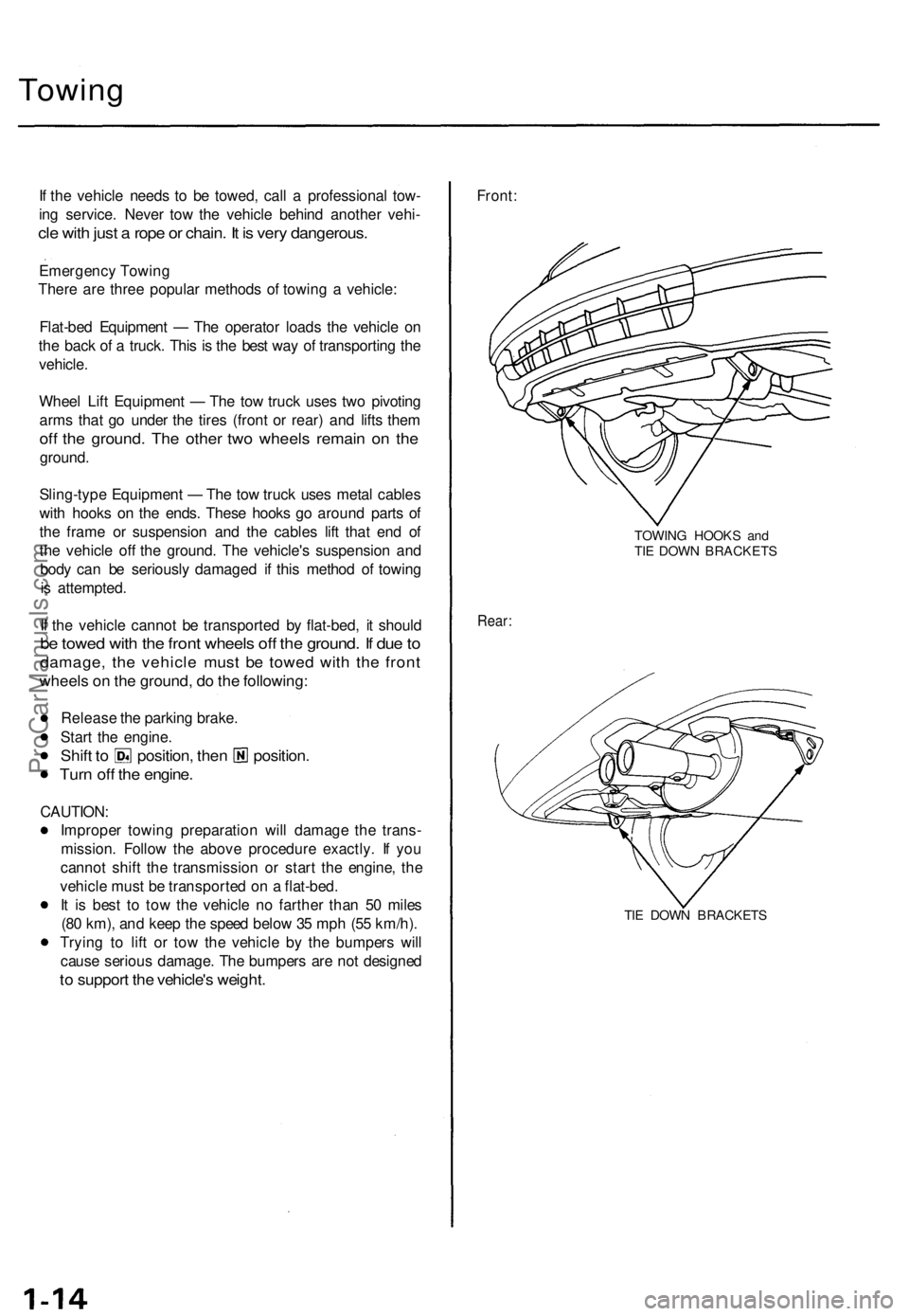
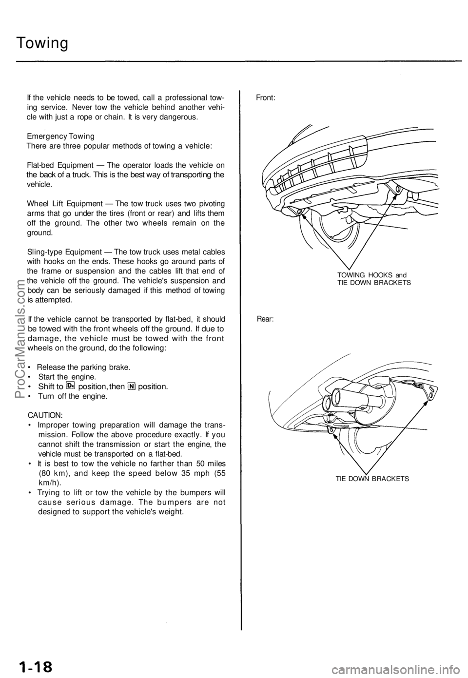
Front:
TOWING HOOKS and
TIE DOWN BRACKETS
Rear:
TIE DOWN BRACKETSProCarManuals.com
Page 48 of 1771
Engine Removal/Installatio n
Removal (cont'd )
30. Remov e th e radiato r cap .
Us e car e whe n removin g th e radiato r
ca p to avoi d scaldin g b y ho t coolan t o r steam .
31 . Rais e th e hois t t o ful l height .
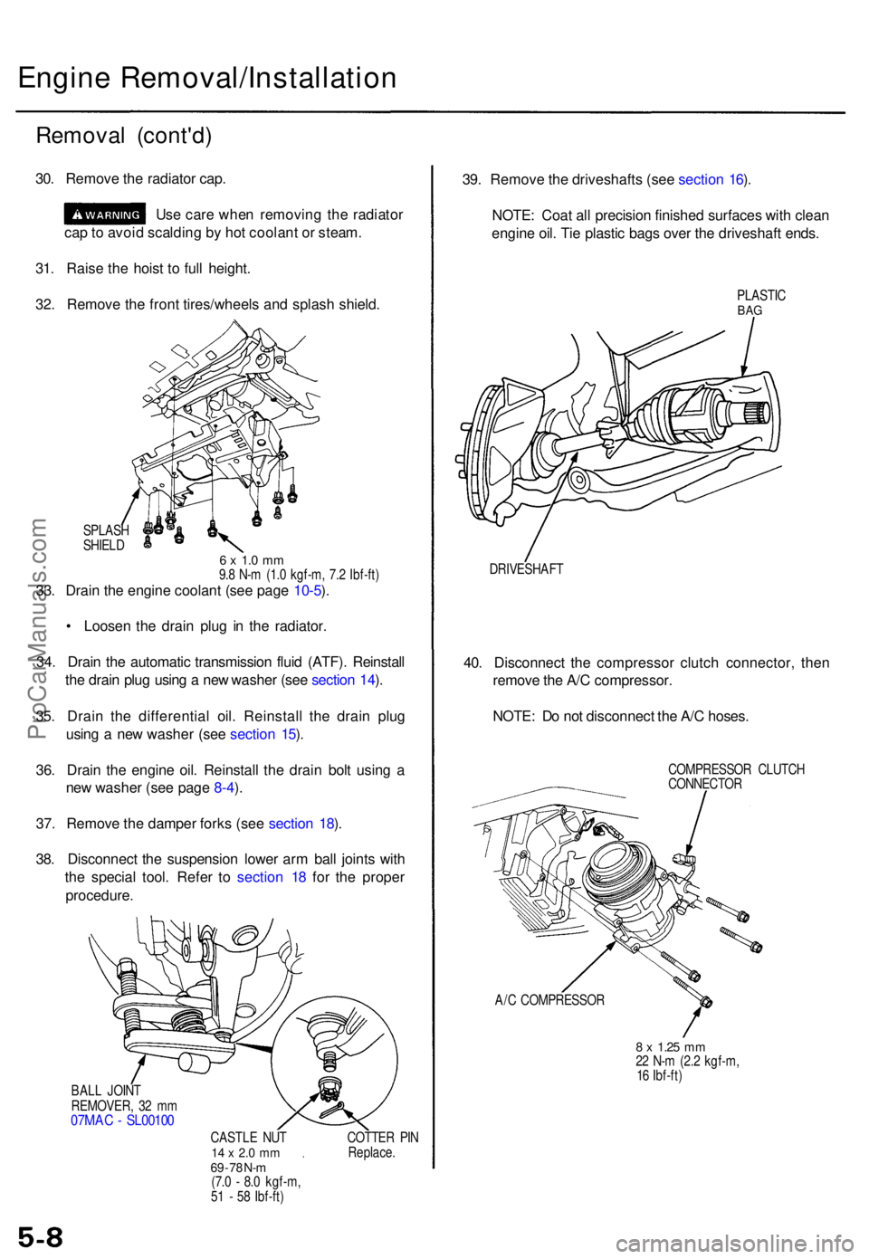
32 . Remov e th e fron t tires/wheel s an d splas h shield .
SPLAS H
SHIEL D
6 x 1. 0 m m9.8 N- m (1. 0 kgf-m , 7. 2 Ibf-ft )33. Drai n th e engin e coolan t (se e pag e 10-5 ).
• Loose n th e drai n plu g i n th e radiator .
34 . Drai n th e automati c transmissio n flui d (ATF) . Reinstal l
th e drai n plu g usin g a ne w washe r (se e sectio n 14 ).
35 . Drai n th e differentia l oil . Reinstal l th e drai n plu g
usin g a ne w washe r (se e sectio n 15 ).
36 . Drai n th e engin e oil . Reinstal l th e drai n bol t usin g a
ne w washe r (se e pag e 8-4 ).
37 . Remov e th e dampe r fork s (se e sectio n 18 ).
38 . Disconnec t th e suspensio n lowe r ar m bal l joint s wit h
th e specia l tool . Refe r t o sectio n 1 8 fo r th e prope r
procedure .
BALL JOIN T
REMOVER , 3 2 m m
07MA C - SL0010 0
CASTLE NU T14 x 2. 0 m m69 - 7 8 N- m(7. 0 - 8. 0 kgf-m ,
5 1 - 5 8 Ibf-ft ) COTTE
R PI N
Replace .
39. Remov e th e driveshaft s (se e sectio n 16 ).
NOTE : Coa t al l precisio n finishe d surface s wit h clea n
engin e oil . Ti e plasti c bag s ove r th e driveshaf t ends .
PLASTI CBAG
DRIVESHAF T
40. Disconnec t th e compresso r clutc h connector , the n
remov e th e A/ C compressor .
NOTE : D o no t disconnec t th e A/ C hoses .
COMPRESSO R CLUTC H
CONNECTO R
A/ C COMPRESSO R
8 x 1.2 5 mm22 N- m (2. 2 kgf-m ,
1 6 Ibf-ft )
ProCarManuals.com
Page 492 of 1771
Component Location s Whee
l Alignmen t
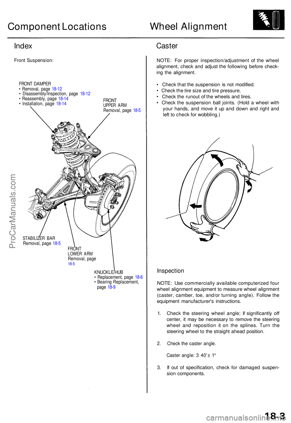
Index
Fron t Suspension :
FRONT DAMPE R
• Removal , pag e 18-1 2
• Disassembly/Inspection , pag e 18-1 2
• Reassembly , pag e 18-1 4
• Installation , pag e 18-1 4 FRON
T
UPPER AR MRemoval , pag e 18- 5
STABILIZE R BA RRemoval , pag e 18- 5
FRON TLOWE R AR MRemoval , pag e18-5
KNUCKLE/HU B
• Replacement , pag e 18- 6
• Bearin g Replacement ,
pag e 18- 9
Caste r
NOTE : Fo r prope r inspection/adjustmen t of the whee l
alignment , chec k an d adjus t th e followin g befor e check -
in g th e alignment .
• Chec k tha t th e suspensio n i s no t modified .
• Chec k th e tir e siz e an d tir e pressure .
• Chec k th e runou t o f th e wheel s an d tires .
• Chec k th e suspensio n bal l joints . (Hol d a whee l wit h
you r hands , an d mov e i t u p an d dow n an d righ t an d
lef t t o chec k fo r wobbling. )
Inspection
NOTE: Us e commerciall y availabl e computerize d fou r
whee l alignmen t equipmen t t o measur e whee l alignmen t
(caster , camber , toe , and/o r turnin g angle) . Follo w th e
equipmen t manufacturer' s instructions .
1 . Chec k th e steerin g whee l angle ; i f significantl y of f
center , i t ma y b e necessar y t o remov e th e steerin g
whee l an d repositio n i t o n th e splines . Tur n th e
steerin g whee l t o th e straigh t ahea d position .
2. Chec k th e caste r angle .
Caster angle : 3 40' ± 1 °
3. I f ou t o f specification , chec k fo r damage d suspen -
sio n components .
ProCarManuals.com
Page 530 of 1771
Construction and Function
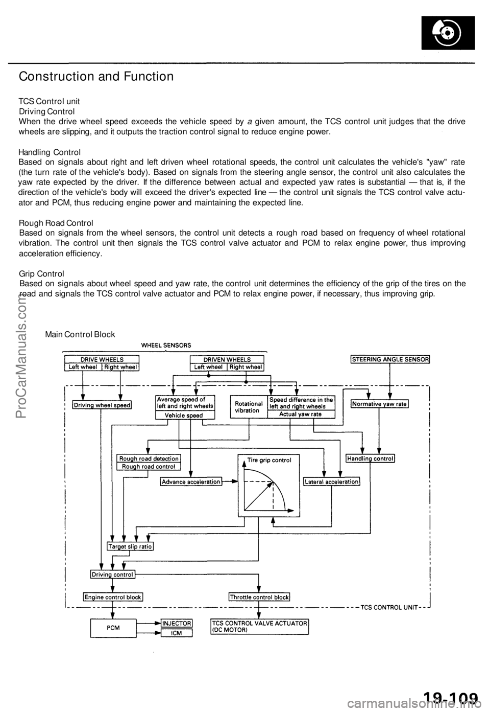
TCS Control unit
Driving Control
When the drive wheel speed exceeds the vehicle speed by a given amount, the TCS control unit judges that the drive
wheels are slipping, and it outputs the traction control signal to reduce engine power.
Handling Control
Based on signals about right and left driven wheel rotational speeds, the control unit calculates the vehicle's "yaw" rate
(the turn rate of the vehicle's body). Based on signals from the steering angle sensor, the control unit also calculates the
yaw rate expected by the driver. If the difference between actual and expected yaw rates is substantial — that is, if the
direction of the vehicle's body will exceed the driver's expected line — the control unit signals the TCS control valve actu-
ator and PCM, thus reducing engine power and maintaining the expected line.
Rough Road Control
Based on signals from the wheel sensors, the control unit detects a rough road based on frequency of wheel rotational
vibration. The control unit then signals the TCS control valve actuator and PCM to relax engine power, thus improving
acceleration efficiency.
Grip Control
Based on signals about wheel speed and yaw rate, the control unit determines the efficiency of the grip of the tires on the
road and signals the TCS control valve actuator and PCM to relax engine power, if necessary, thus improving grip.
Main Control BlockProCarManuals.com
Page 688 of 1771
Towing
If the vehicle needs to be towed, call a professional tow-
ing service. Never tow the vehicle behind another vehi-
cle with just a rope or chain. It is very dangerous.
Emergency Towing
There are three popular methods of towing a vehicle:
Flat-bed Equipment — The operator loads the vehicle on
the back of a truck. This is the best way of transporting the
vehicle.
Wheel Lift Equipment — The tow truck uses two pivoting
arms that go under the tires (front or rear) and lifts them
off the ground. The other two wheels remain on the
ground.
Sling-type Equipment — The tow truck uses metal cables
with hooks on the ends. These hooks go around parts of
the frame or suspension and the cables lift that end of
the vehicle off the ground. The vehicle's suspension and
body can be seriously damaged if this method of towing
is attempted.
If the vehicle cannot be transported by flat-bed, it should
be towed with the front wheels off the ground. If due to
damage, the vehicle must be towed with the front
wheels on the ground, do the following:
• Release the parking brake.
• Start the engine.
• Shift to position, then position.
• Turn off the engine.
CAUTION:
• Improper towing preparation will damage the trans-
mission. Follow the above procedure exactly. If you
cannot shift the transmission or start the engine, the
vehicle must be transported on a flat-bed.
• It is best to tow the vehicle no farther than 50 miles
(80 km), and keep the speed below 35 mph (55
km/h).
• Trying to lift or tow the vehicle by the bumpers will
cause serious damage. The bumpers are not
designed to support the vehicle's weight.
Front:
TOWING HOOKS and
TIE DOWN BRACKETS
Rear:
TIE DOWN BRACKETSProCarManuals.com
Page 723 of 1771
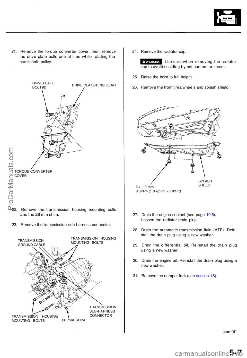
21. Remov e th e torqu e converte r cover , the n remov e
the driv e plat e bolt s on e a t tim e whil e rotatin g th e
crankshaf t pulley .
DRIVE PLAT E
BOL T (8 ) DRIV
E PLATE/RIN G GEA R
TORQU E CONVERTE R
COVER
22. Remov e th e transmissio n housin g mountin g bolt s
and th e 2 6 m m shim .
23. Remov e th e transmissio n sub-harnes s connector .
TRANSMISSIO N
GROUN D CABL E TRANSMISSIO
N HOUSIN G
MOUNTIN G BOLT S
24. Remov e th e radiato r cap .
Us e car e whe n removin g th e radiato r
ca p to avoi d scaldin g b y ho t coolan t o r steam .
25 . Rais e th e hois t t o ful l height .
26 . Remov e th e fron t tires/wheel s an d splas h shield .
6 x 1. 0 m m9.8 N- m (1. 0 kgf-m , 7. 2 Ibf-ft )
SPLAS HSHIELD
27. Drai n th e engin e coolan t (se e pag e 10-5 ).
Loose n th e radiato r drai n plug .
28 . Drai n th e automati c transmissio n flui d (ATF) . Rein -
stal l th e drai n plu g usin g a ne w washer .
29 . Drai n th e differentia l oil . Reinstal l th e drai n plu g
usin g a ne w washer .
30 . Drai n th e engin e oil . Reinstal l th e drai n plu g usin g a
ne w washer .
31 . Remov e th e dampe r for k (se e sectio n 18 ).
2 6 m m SHI M
TRANSMISSIO NSUB-HARNESSCONNECTOR
TRANSMISSIO N HOUSIN G
MOUNTIN G BOLT S
ProCarManuals.com
Page 1218 of 1771
Wheel Alignmen t
Caster
NOTE : Fo r prope r inspection/adjustmen t o f th e whee l
alignment , chec k an d adjus t th e followin g befor e check -
ing th e alignment .
• Chec k tha t th e suspensio n i s no t modified .
• Chec k th e tir e siz e an d tir e pressure .
• Chec k th e runou t o f th e wheel s an d tires .
• Chec k th e suspensio n bal l joints . (Hol d th e whee l wit h
you r hands , the n mov e i t u p an d down , an d righ t an d
lef t t o chec k fo r wobbling. )
Inspection
NOTE: Us e commercially-availabl e computerize d fou r
whee l alignmen t equipmen t t o measur e whee l align -
men t (caster , camber , toe , and/o r turnin g angle) .
Follo w th e equipmen t manufacturer' s instructions .
1 . Chec k th e caste r angle .
Caste r angle : 2°07 ' ± 1 °
2 . I f ou t o f specification , recor d th e caste r reading , the n
adjus t th e caster .
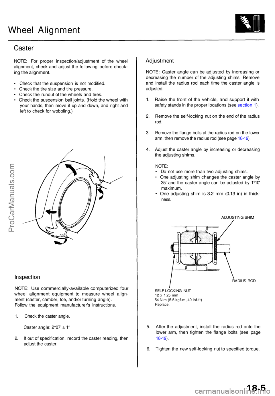
Adjustmen t
NOTE: Caste r angl e ca n b e adjuste d b y increasin g o r
decreasin g th e numbe r o f th e adjustin g shims . Remov e
an d instal l th e radiu s ro d eac h tim e th e caste r angl e i s
adjusted .
1. Rais e th e fron t o f th e vehicle , an d suppor t i t wit h
safet y stand s in th e prope r location s (se e sectio n 1 ).
2 . Remov e th e self-lockin g nu t o n th e en d o f th e radiu s
rod.
3. Remov e th e flang e bolt s a t th e radiu s ro d o n th e lowe r
arm , the n remov e th e radiu s ro d (se e pag e 18-19 ).
4 . Adjus t th e caste r angl e b y increasin g o r decreasin g
the adjustin g shims .
NOTE:
• D o no t us e mor e tha n tw o adjustin g shims .
• On e adjustin g shi m change s th e caste r angl e b y
35 ' an d th e caste r angl e ca n b e adjuste d b y 1°10 '
maximum .
• On e adjustin g shi m is 3. 2 m m (0.1 3 in ) i n thick -
ness.
ADJUSTIN G SHI M
RADIU S RO D
SELF-LOCKIN G NU T
12 x 1.2 5 mm54 N- m (5. 5 kgf-m , 4 0 Ibf-ft )Replace .
5. Afte r th e adjustment , instal l th e radiu s ro d ont o th e
lowe r arm , the n tighte n th e flang e bolt s (se e pag e
18-19 ).
6 . Tighte n th e ne w self-lockin g nu t t o specifie d torque .
ProCarManuals.com
Page 1323 of 1771
Anti-lock Brak e Syste m (ABS )
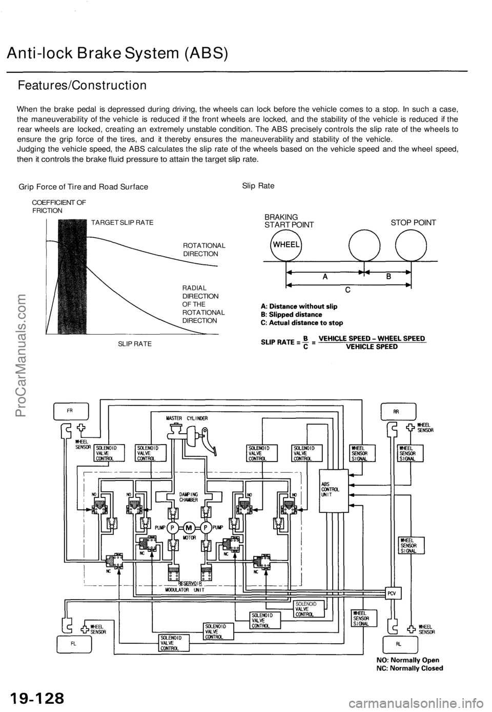
Features/Constructio n
When th e brak e peda l i s depresse d durin g driving , th e wheel s ca n loc k befor e th e vehicl e come s t o a stop . I n suc h a case ,
th e maneuverabilit y o f th e vehicl e i s reduce d i f th e fron t wheel s ar e locked , an d th e stabilit y o f th e vehicl e i s reduce d i f th e
rea r wheel s ar e locked , creatin g a n extremel y unstabl e condition . Th e AB S precisel y control s th e sli p rat e o f th e wheel s t o
ensur e th e gri p forc e o f th e tires , an d i t thereb y ensure s th e
maneuverability an d stabilit y o f th e vehicle .
Judgin g th e vehicl e speed , th e AB S calculate s th e sli p rat e o f th e wheel s base d o n th e vehicl e spee d an d th e whee l speed ,
then it control s th e brak e flui d pressur e to attai n th e targe t sli p rate .
Grip Forc e o f Tir e an d Roa d Surfac e Sli
p Rat e
COEFFICIEN T O FFRICTIO N
TARGET SLI P RAT E
SLI P RAT E ROTATIONA
L
DIRECTIO N
RADIALDIRECTIO NOF TH EROTATIONA L
DIRECTIO N
BRAKINGSTART POIN T STO
P POIN T
SOLENOI D
ProCarManuals.com