heating ACURA TL 1995 Service Repair Manual
[x] Cancel search | Manufacturer: ACURA, Model Year: 1995, Model line: TL, Model: ACURA TL 1995Pages: 1771, PDF Size: 62.49 MB
Page 442 of 1771
Differential Assembl y
Disassembl y (cont'd )
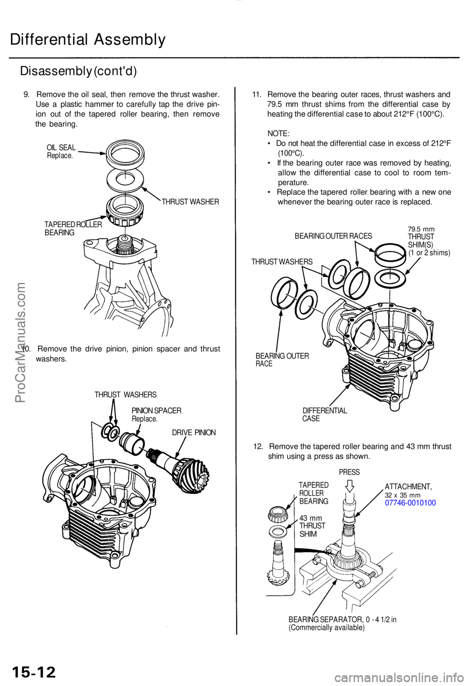
9. Remov e th e oi l seal , the n remov e th e thrus t washer .
Us e a plasti c hamme r t o carefull y ta p th e driv e pin -
io n ou t o f th e tapere d rolle r bearing , the n remov e
th e bearing .
OIL SEA LReplace .
TAPERE D ROLLE RBEARIN G
THRUST WASHE R
10. Remov e th e driv e pinion , pinio n space r an d thrus t
washers .
THRUST WASHER S
PINION SPACE RReplace .
DRIVE PINIO N
11. Remov e th e bearin g oute r races , thrus t washer s an d
79. 5 m m thrus t shim s fro m th e differentia l cas e b y
heatin g th e differentia l cas e to abou t 212° F (100°C) .
NOTE:
• D o no t hea t th e differentia l cas e in exces s o f 212° F
(100°C) .
• I f th e bearin g oute r rac e wa s remove d b y heating ,
allo w th e differentia l cas e t o coo l t o roo m tem -
perature .
• Replac e th e tapere d rolle r bearin g wit h a ne w on e
wheneve r th e bearin g oute r rac e is replaced .
BEARING OUTE R RACE S79.5 mmTHRUS T
SHIM(S )
( 1 o r 2 shims )
THRUS T WASHER S
BEARIN G OUTE R
RACE
DIFFERENTIA LCASE
12. Remov e th e tapere d rolle r bearin g an d 4 3 m m thrus t
shi m usin g a pres s a s shown .
ATTACHMENT ,32 x 35 m m07746-001010 0
BEARING SEPARATOR , 0 - 4 1/ 2 in
(Commerciall y available )
TAPEREDROLLERBEARIN G
43 m mTHRUS TSHIM
PRES S
ProCarManuals.com
Page 470 of 1771
Inspection an d Adjustmen t
Pump Pressur e Chec k (cont'd )
7. Star t th e engin e an d le t i t idle .
8 . Tur n th e steerin g whee l fro m lock-to-loc k severa l
time s to war m th e flui d to operatin g temperature .
9 . Measur e steady-stat e flui d pressur e whil e idling . I f
th e pum p i s i n goo d condition , th e gaug e shoul d
rea d les s tha n 150 0 kP a (1 5 kgf/cm
2, 21 3 psi) .
I f i t read s high , chec k th e outle t hos e o r valv e bod y
uni t (refe r t o th e '9 5 - 9 8 Acur a 2.5T L Servic e
Manual , P/ N 61SW504 , fo r Genera l Troubleshoot -
ing).
10. Clos e th e pressur e contro l valve , the n clos e th e
shut-of f valv e graduall y unti l th e pressur e gaug e
needl e is stable . Rea d th e pressure .
11 . Immediatel y ope n th e pressur e contro l valv e fully .
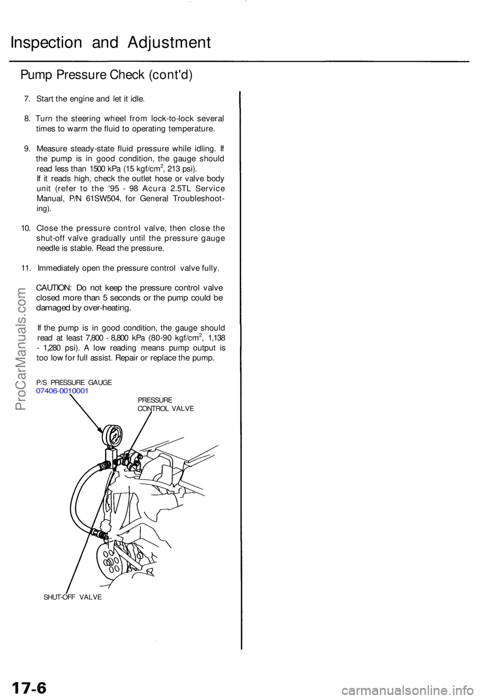
CAUTION : D o no t kee p th e pressur e contro l valv e
close d mor e tha n 5 second s o r th e pum p coul d b e
damage d b y over-heating .
If th e pum p i s i n goo d condition , th e gaug e shoul d
rea d a t leas t 7,80 0 - 8,80 0 kP a (80-9 0 kgf/cm2, 1,13 8
- 1,28 0 psi) . A lo w readin g mean s pum p outpu t i s
to o lo w fo r ful l assist . Repai r o r replac e th e pump .
SHUT-OF F VALV E
PRESSUR ECONTROL VALV E
P/
S PRESSUR E GAUG E
07406-001000 1
ProCarManuals.com
Page 671 of 1771
General Info
Specifications
Maintenance
Engine
Cooling
Fuel and Emissions
2.5L
3.2L
* Transaxle
SteeringSuspension
* Brakes (Including ABS)
* Body
* Heating, Ventilation
and Air Conditioning
* Body Electrical
* Engine Electrical
* SRS2.5L
3.2L
1995±98 TL Main Menu
As sections w/ * include SRS components, special precautions are required when servicing.
ProCarManuals.com
Page 1167 of 1771
Pump Pressur e Chec k
Chec k th e flui d pressur e a s follow s t o determin e
whethe r th e troubl e i s i n th e pum p o r gearbox .
NOTE : Firs t chec k th e powe r steerin g flui d leve l an d
pum p bel t tension .
CAUTION : Disconnec t th e hig h pressur e hos e wit h car e
s o a s no t t o spil l th e powe r steerin g flui d o n th e fram e
an d othe r parts .
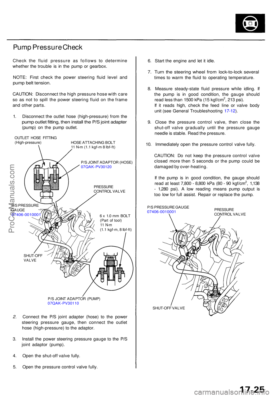
1 . Disconnec t th e outle t hos e (high-pressure ) fro m th e
pum p outle t fitting , the n instal l th e P/ S join t adapte r
(pump) o n th e pum p outlet .
OUTLE T HOS E FITTIN G
(High-pressure )
P/ S PRESSUR E
GAUG E
07406-001000 1
HOSE ATTACHIN G BOL T
1 1 N- m (1. 1 kgf- m 8 Ibf-ft )
P/ S JOIN T ADAPTO R (HOSE )
07QAK-PV3012 0
PRESSURECONTROL VALV E
6 x 1. 0 m m BOL T
(Par t o f tool )
11 N- m(1.1 kgf-m , 8 Ibf-ft )
SHUT-OF F
VALVE
P/S JOIN T ADAPTO R (PUMP )
07QAK-PV3011 0
2. Connec t th e P/ S join t adapte r (hose ) t o th e powe r
steerin g pressur e gauge , the n connec t th e outle t
hos e (high-pressure ) t o th e adaptor .
3 . Instal l th e powe r steerin g pressur e gaug e t o th e P/ S
join t adapto r (pump) .
4 . Ope n th e shut-of f valv e fully .
5 . Ope n th e pressur e contro l valv e fully . 6
. Star t th e engine and le t i t idle .
7. Tur n th e steerin g whee l fro m lock-to-loc k severa l
times t o war m th e flui d t o operating temperature .
8 . Measur e steady-stat e flui d pressur e whil e idling . I f
th e pum p i s i n goo d condition , th e gaug e shoul d
rea d les s tha n 150 0 kP a (1 5 kgf/cm
2, 21 3 psi) .
I f i t read s high , chec k th e fee d lin e o r valv e bod y
uni t (se e Genera l Troubleshootin g 17-12 ).
9 . Clos e th e pressur e contro l valve , the n clos e th e
shut-of f valv e graduall y unti l th e pressur e gaug e
needl e is stable . Rea d th e pressure .
10 . Immediatel y ope n th e pressur e contro l valv e fully .
CAUTION : D o no t kee p th e pressur e contro l valv e
close d mor e the n 5 second s o r th e pum p coul d b e
damage d b y over-heating .
I f th e pum p i s i n goo d condition , th e gaug e shoul d
rea d a t leas t 7,80 0 - 8,80 0 kP a (8 0 - 9 0 kgf/cm
2, 1,13 8
- 1,28 0 psi) . A lo w readin g mean s pum p outpu t i s
to o lo w fo r ful l assist . Repai r o r replac e th e pump .
P/S PRESSUR E GAUG E07406-001000 1 PRESSUR ECONTROL VALV E
SHUT-OF F VALV E
ProCarManuals.com
Page 1462 of 1771
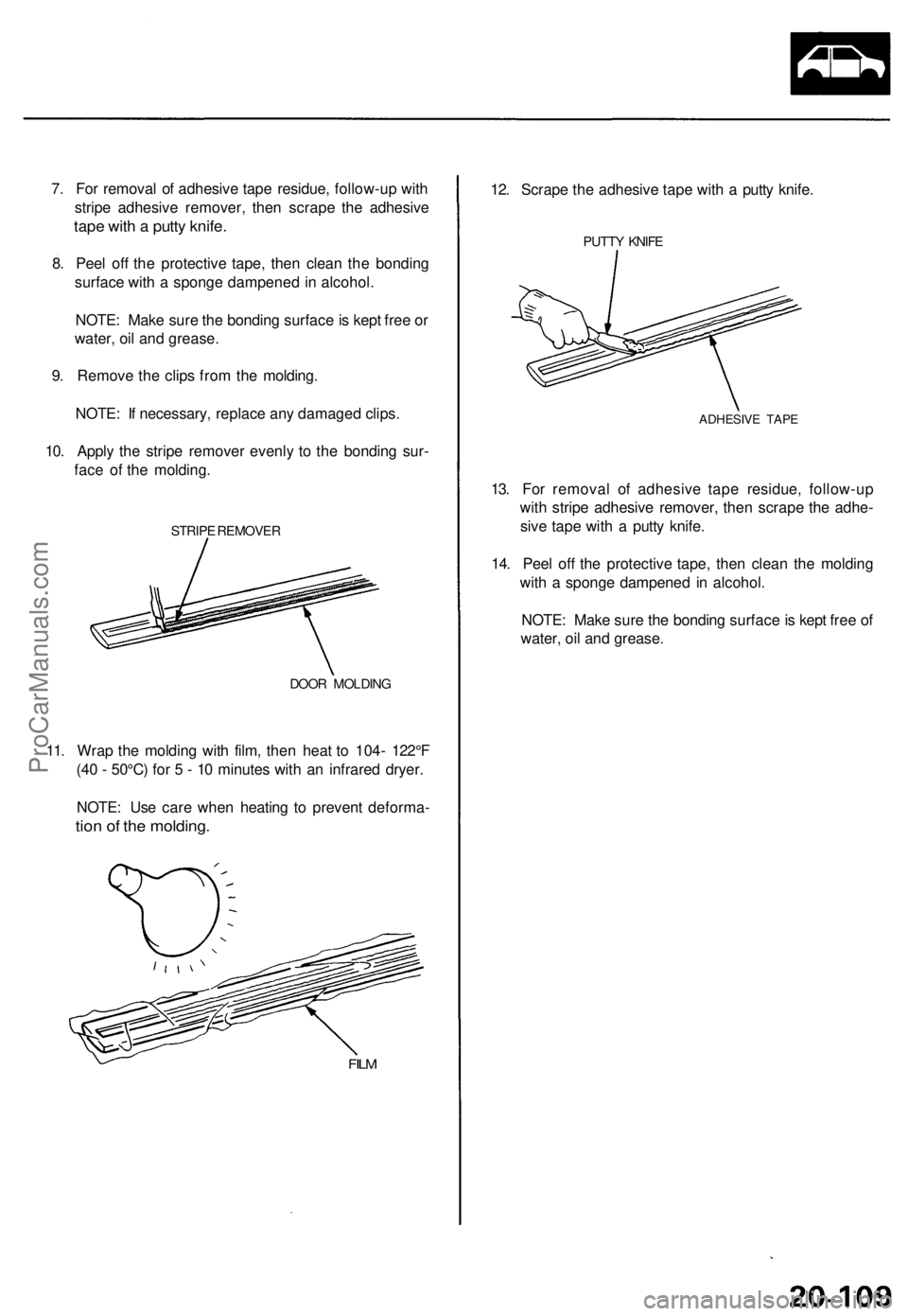
7. For removal of adhesive tape residue, follow-up with
stripe adhesive remover, then scrape the adhesive
tape with a putty knife.
8. Peel off the protective tape, then clean the bonding
surface with a sponge dampened in alcohol.
NOTE: Make sure the bonding surface is kept free or
water, oil and grease.
9. Remove the clips from the molding.
NOTE: If necessary, replace any damaged clips.
10. Apply the stripe remover evenly to the bonding sur-
face of the molding.
STRIPE REMOVER
DOOR MOLDING
11. Wrap the molding with film, then heat to 104- 122°F
(40 - 50°C) for 5 - 10 minutes with an infrared dryer.
NOTE: Use care when heating to prevent deforma-
tion of the molding.
FILM
12. Scrape the adhesive tape with a putty knife.
PUTTY KNIFE
ADHESIVE TAPE
13. For removal of adhesive tape residue, follow-up
with stripe adhesive remover, then scrape the adhe-
sive tape with a putty knife.
14. Peel off the protective tape, then clean the molding
with a sponge dampened in alcohol.
NOTE: Make sure the bonding surface is kept free of
water, oil and grease.ProCarManuals.com
Page 1463 of 1771
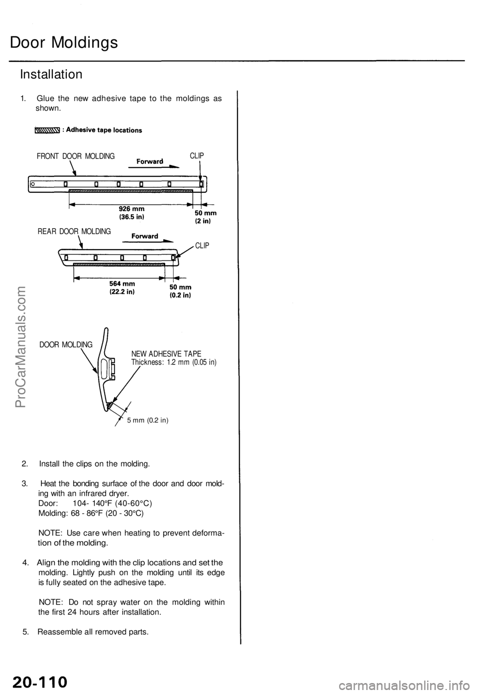
Door Moldings
Installation
1. Glue the new adhesive tape to the moldings as
shown.
FRONT DOOR MOLDING
CLIP
DOOR MOLDING
NEW ADHESIVE TAPE
Thickness: 1.2 mm (0.05 in)
5 mm
(0.2
in)
2. Install the clips on the molding.
3. Heat the bonding surface of the door and door mold-
ing with an infrared dryer.
Door: 104- 140°F (40-60°C)
Molding: 68 - 86°F (20 - 30°C)
NOTE: Use care when heating to prevent deforma-
tion of the molding.
4. Align the molding with the clip locations and set the
molding. Lightly push on the molding until its edge
is fully seated on the adhesive tape.
NOTE: Do not spray water on the molding within
the first 24 hours after installation.
5. Reassemble all removed parts.
REAR DOOR MOLDING
CLIPProCarManuals.com