steering Alfa Romeo 156 2004 Owner handbook (in English)
[x] Cancel search | Manufacturer: ALFA ROMEO, Model Year: 2004, Model line: 156, Model: Alfa Romeo 156 2004Pages: 357, PDF Size: 5.04 MB
Page 58 of 357
GETTING TO KNOW YOUR CAR56
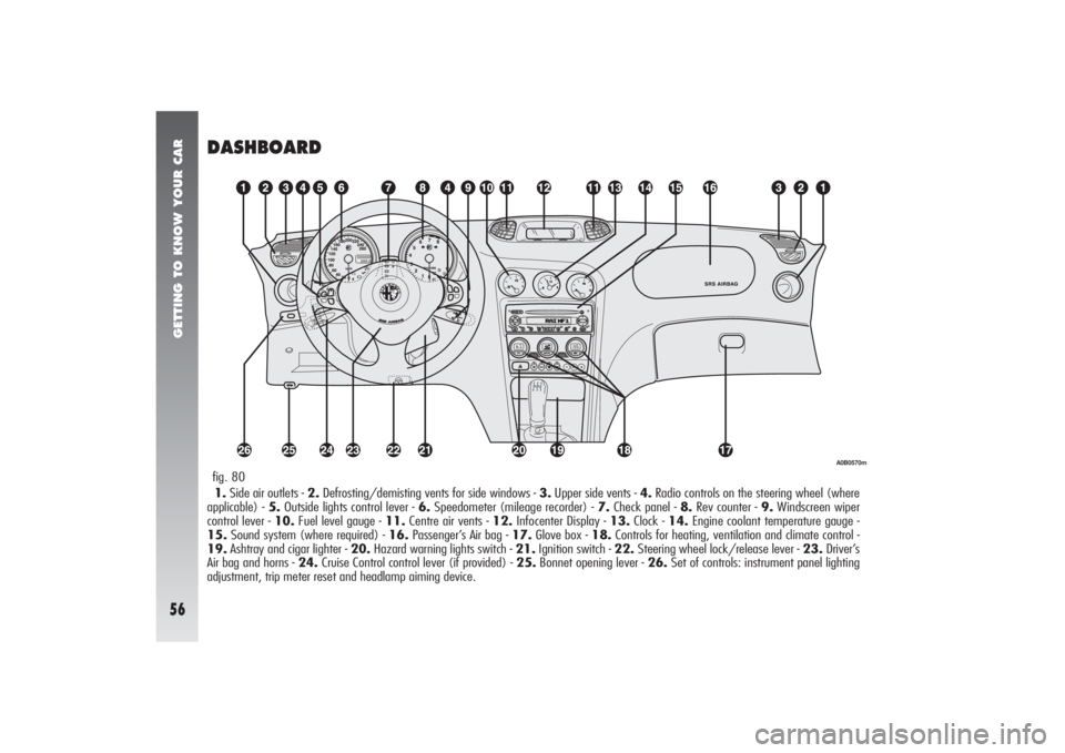
DASHBOARD1.Side air outlets - 2.Defrosting/demisting vents for side windows - 3.Upper side vents - 4.Radio controls on the steering wheel (where
applicable) - 5.Outside lights control lever - 6.Speedometer (mileage recorder) - 7.Check panel - 8.Rev counter - 9.Windscreen wiper
control lever - 10.Fuel level gauge - 11.Centre air vents - 12.Infocenter Display - 13.Clock - 14.Engine coolant temperature gauge -
15.Sound system (where required) - 16.Passenger’s Air bag - 17.Glove box - 18.Controls for heating, ventilation and climate control -
19.Ashtray and cigar lighter - 20.Hazard warning lights switch - 21.Ignition switch - 22.Steering wheel lock/release lever - 23.Driver’s
Air bag and horns - 24.Cruise Control control lever (if provided) - 25.Bonnet opening lever - 26.Set of controls: instrument panel lighting
adjustment, trip meter reset and headlamp aiming device.fig. 80
A0B0570m
Page 140 of 357

GETTING TO KNOW YOUR CAR
138
HEADLIGHT CORRECTOR (fig. 121)
If the car is fitted with xenon headlights,
beam aiming is electronic and therefore con-
trol (A) on the mask near the steering col-
umn is not present.
The headlights should be aimed correctly
depending on the vehicle load.
The control (A) on the plate at the side of
the steering column can be moved to four
positions corresponding to the vehicle loads
given below:
position 0: 1 or 2 people occupying front
seats, full fuel tank, on-board equipment pre-
sent;
position 1: 5 people on-board;fig. 121
A0B0240m
HAND BRAKE
(fig. 122)
The hand brake lever is located between
the two front seats.
To operate the brake when the vehicle is
“stationary”, pull the lever (A) upwards un-
til the required braking action is obtained.
When the ignition key is in the MARpo-
sition, the
x
warning light will come on on
the instrument panel.
fig. 122
A0B0288m
position 2: 5 people on-board, luggage
compartment full (50 kg approximately);
position 3: Driver and 300 kg in luggage
compartment.
Check the positioning of
the headlight beams every
time you change the load to be car-
ried.
WARNING
Page 143 of 357
GETTING TO KNOW YOUR CAR
141
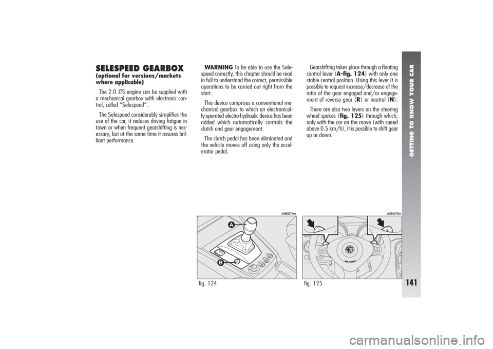
Gearshifting takes place through a floating
control lever (A-fig. 124) with only one
stable central position. Using this lever it is
possible to request increase/decrease of the
ratio of the gear engaged and/or engage-
ment of reverse gear (R) or neutral (N).
There are also two levers on the steering
wheel spokes (fig. 125) through which,
only with the car on the move (with speed
above 0.5 km/h), it is possible to shift gear
up or down.
SELESPEED GEARBOX (optional for versions/markets
where applicable)
The 2.0 JTS engine can be supplied with
a mechanical gearbox with electronic con-
trol, called “Selespeed”.
The Selespeed considerably simplifies the
use of the car, it reduces driving fatigue in
town or when frequent gearshifting is nec-
essary, but at the same time it assures bril-
liant performance.WARNINGTo be able to use the Sele-
speed correctly, this chapter should be read
in full to understand the correct, permissible
operations to be carried out right from the
start.
This device comprises a conventional me-
chanical gearbox to which an electronical-
ly-operated electro-hydraulic device has been
added which automatically controls the
clutch and gear engagement.
The clutch pedal has been eliminated and
the vehicle moves off using only the accel-
erator pedal.
fig. 124
A0B0271m
fig. 125
A0B0270m
Page 144 of 357
GETTING TO KNOW YOUR CAR
142
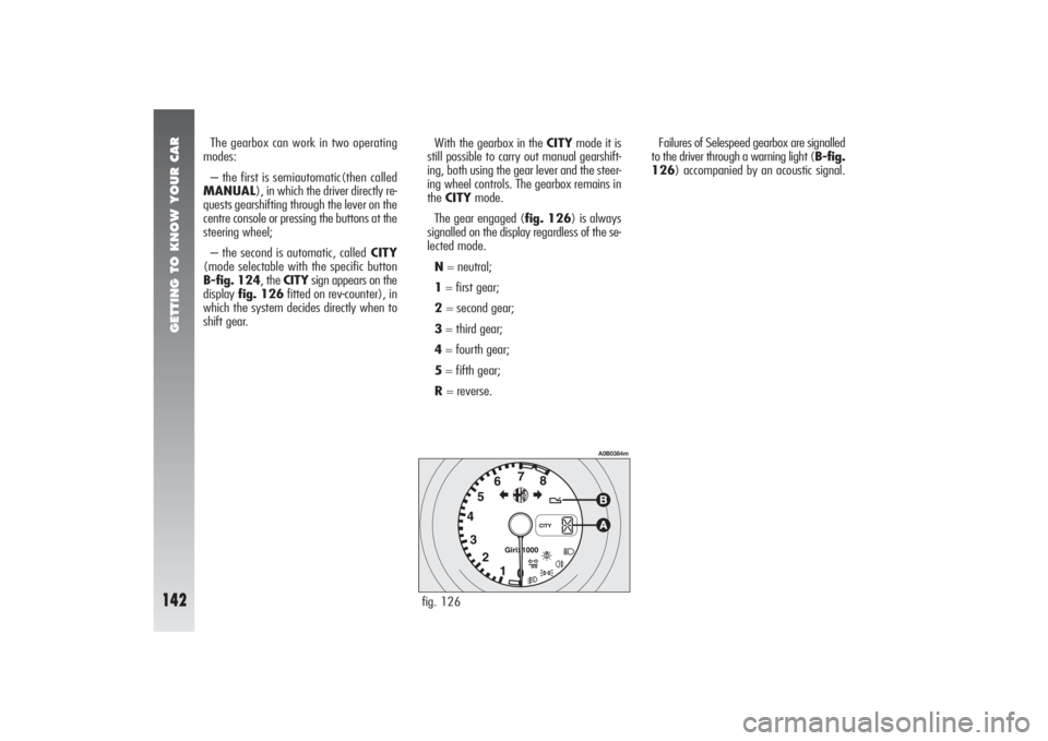
Failures of Selespeed gearbox are signalled
to the driver through a warning light (B-fig.
126) accompanied by an acoustic signal. The gearbox can work in two operating
modes:
– the first is semiautomatic(then called
MANUAL), in which the driver directly re-
quests gearshifting through the lever on the
centre console or pressing the buttons at the
steering wheel;
– the second is automatic, calledCITY
(mode selectable with the specific button
B-fig. 124, the CITYsign appears on the
display fig. 126fitted on rev-counter), in
which the system decides directly when to
shift gear.With the gearbox in the CITYmode it is
still possible to carry out manual gearshift-
ing, both using the gear lever and the steer-
ing wheel controls. The gearbox remains in
the CITYmode.
The gear engaged (fig. 126) is always
signalled on the display regardless of the se-
lected mode.
N= neutral;
1= first gear;
2 = second gear;
3= third gear;
4= fourth gear;
5= fifth gear;
R= reverse.
fig. 126
A0B0384m
Page 147 of 357
GETTING TO KNOW YOUR CAR
145
STARTING THE ENGINEThe engine can be started with the gear
engaged or in neutral (N), provided that the
brake pedal is pressed down.
WARNINGKeep the brake pedal
pressed during the starting operation. As the
brake pedal stiffens if it is pressed repeat-
edly with the engine off, in this situation, to
allow the engine to be started, it is neces-
sary to increase the pressure exerted on the
pedal itself.
After starting, the gearbox automatically
sets to neutral, the display shows the let-
ter (N) and the system selects the operat-
ing mode stored before switching off.
TURNING THE ENGINE OFF
AND SYSTEM DEACTIVATIONTurning the ignition key to STOPthe en-
gine switches off but the Selespeed system
still remains active, waiting for the vehicle
to stop completely. After about 2 - 4 seconds
from when the key has been turned to the
STOPposition, the hydraulic part is deac-
tivated and immediately afterwards the dis-
play on the rev counteralso goes out ; the
Selespeed system is only deactivated at this
point.
The gear selected before turning the en-
gine off remains engaged.
If the engine stops with the gearbox in
neutral (N), the buzzer draws the attention
of the driver so that the vehicle can be put
in safety conditions engaging the first gear
(1) or reverse (R). In this case, it is nec-
essary to turn the ignition key to MARand
with the brake pedal pressed, engage first
gear (1) or reverse (R).
If the engine fails to start
with the gear engaged, the
driver is alerted of the potentially
dangerous situation due to the fact
that the gearbox has automatically
set to neutral by the buzzer and
the display on the rev counter.
WARNING
NEVER leave the car with
the gearbox in neutral (N).
WARNING
Never remove the key
when the car is on the
move, because in addition to the
fact that the Selespeed system
would not work properly until
stopping the car, the steering
wheel would automatically lock at
the first turn.
WARNING
It is absolutely necessary
to turn off the engine con-
sequently deactivating the Sele-
speed system keeping the brake
pedal pressed: release the pedal
ONLY when the display on the rev
counter goes off.
WARNING
Page 148 of 357
GETTING TO KNOW YOUR CAR
146
WARNINGS– With the vehicle stationary and a gear
engaged, always keep the brake pedal
pressed until you decide to move off;
– in prolonged stops with the engine run-
ning it is advisable to keep the gearbox is
neutral;
– when the car is parked on a slope, do
not use the pick-up manoeuvre to keep the
vehicle stopped; use the brake pedal and
work on the accelerator pedal only when
you decide to move off;
– use second gear onlywhen necessary
to obtain better control of pick-up in low
speed manoeuvres;
– if, with reverse gear engaged, you need
to engage first gear or vice versa, shift gear
only when the car is completely stationary
and with the brake pedal pressed. This should not be considered as a fault as
it is part of the operating logic. For the same
reason, in the event of sticking on reverse,
the system commands partial clutch closing
to allow engagement of the gear; in this
case engagement of reverse gear (R) will
be less comfortable.
Moving off of the vehicle is obtained:
1) releasing the brake pedal;
2) gradually operating the accelerator
pedal.
The vehicle pick-up torque is higher the
more the accelerator pedal is pressed.
MOVING OFFWith the engine running and the vehicle
stationary, the gears that can be engaged
for moving off are only first (1), second (2)
or reverse (R).
To engage them it is possible to use the
control lever on the centre console, with the
brake pedal pressed, as the levers on the
steering wheel allow gear engagement only
over 0.5 km/h.
WARNINGReverse gear (R) can be en-
gaged from each of the following other ra-
tios: neutral (N), first gear (1) or second
gear (2). If the car is on the move, the re-
quest is not accepted; it is necessary to wait
for the car to be completely stopped and
then request reverse (R) again.
The driver is informed of the reverse gear
engaged condition by the intermittent sound
of the buzzer as well as by the display on
the rev counter.
WARNINGIf while shifting from reverse
(R)/first gear (1) to neutral (N)/first gear
(1) sticking occurs on the first gear, the sys-
tem automatically engages second gear
(2).
After a request to shift
gear with the vehicle sta-
tionary, before pressing the accel-
erator pedal to make the car start,
the driver must always check that
the gear engaged shown on the
display is the one required.
WARNING
Page 150 of 357

GETTING TO KNOW YOUR CAR
148
fig. 131
A0B0270m
OPERATIONThe gearbox can work in two operating
modes:
– the first is semiautomatic (MANUAL),
in which the driver directly decides when to
shift gear;
– the second is completely automatic
(CITY), in which the system decides di-
rectly when to shift gear according to the
type of driving.
The CITYmode can be selected by press-
ing the specific button CITYon the gearbox
lever knob; when this mode is selected, the
CITY sign appears on the display fitted on
rev counter.
SEMIAUTOMATIC OPERATION
(MANUAL) In the MANUALoperating mode the dis-
play on the rev counter shows the gear en-
gaged.
In this operating mode, the decision to
change gear is left to the driver who decides
the most appropriate moment.
The requests to change gear can take place
through:
– the control lever on the centre console
(A-fig. 130);
– the levers on the steering wheel
(fig. 131), which can be used only when
the vehicle speed exceeds 0.5 km/h.The MANUALoperating mode is set
when, with the CITYmode selected, the
CITYbutton (B-fig. 130) is pressed
again, excluding the previously selected
mode.fig. 130
A0B0271m
Page 167 of 357

GETTING TO KNOW YOUR CAR
165
fig. 151
A0B0283m
ODDMENTS RECESSES ON
CENTRE CONSOLE
(fig. 151)
Centre recess
On the centre console near the handbrake
lever, there are the following oddments re-
cesses:
– oddments recesses (A) and (B);
– coin recess (C).
ODDMENTS RECESSES
ON DASHBOARDLeft side recess (fig. 152)
An oddments recess (A) is provided on the
lower side of the dashboard, on the left of
the steering column.fig. 152
A0B0254m
FRONT DOORS
COMPARTMENTS AND POCKETS(fig. 153)
Each front door has an oddments pocket
(A).fig. 153
A0B0253m
Page 177 of 357

GETTING TO KNOW YOUR CAR
175
COMPENSATION FOR TILT(fig. 169)
If the car is fitted with xenon headlights,
beam aiming is electronic and therefore con-
trol (A) on the mask near the steering col-
umn is not present.
When the vehicle is loaded, the beam from
the headlights is raised due to the back-
wards tilt of the vehicle.
In this case the headlights must be ad-
justed using control (A) located on the plate
at the side of the steering column.This control has four positions corre-
sponding to various vehicle loads given be-
low:
– position 0: 1 or 2 people occupying
front seats, full fuel tank, on-board equip-
ment present;
– position 1: 5 people on-board;
– position 2: 5 people on-board, luggage
compartment full (50 kg approximately);
– position 3: driver and 300 kg in lug-
gage compartment.fig. 169
A0B0240m
Check the positioning of
the headlight beams every
time you change the load to be car-
ried.
WARNING
ADJUSTING THE FRONT
FOGLIGHTS (for versions/markets where
applicable)
To adjust the height of the beam of the
front foglights, act on adjusting screw (A-
fig. 170).fig. 170
A0B0239m
Contact Alfa Romeo Au-
thorized Services to have
the headlights correctly ad-
justed.
Page 182 of 357

GETTING TO KNOW YOUR CAR
180
The heart of the VDC system is the VDC
control unit which with the data supplied by
the sensors installed on the car, calculates
the centrifugal forces generated when the
car is cornering. The yawing sensor detects
the rotations of the car around its own ver-
tical axis. The centrifugal forces generated
when the car is cornering are detected by
a highly sensitive lateral acceleration sensor.
The stabilising action of the VDC system is
based on calculations made by the
system’s electronic control unit which
processes the signals received from the
steering wheel rotation, lateral acceleration
and individual wheel rotation sensors. These
signals allow the control unit to recognise
the manoeuvre the driver intends to do
when turning the steering wheel.
The control unit processes the information
received from the sensors and is therefore
capable of detecting the position of the car
and comparing it with the trajectory the dri-
ver would like to follow instant by instant.
In the event of a discrepancy, the control
unit chooses and commands the most suit-
able action to bring the car back to the re-
quired course within a fraction of a second:
braking one or more wheels at a different
braking force and, if necessary it reduces the
power transmitted by the engine. The corrective actions are changed and con-
trolled continuously until the car returns to
the required course.
The action of the VDC system considerably
increases the active safety of the vehicle un-
der many critical situations and it is partic-
ularly useful also when the road surface grip
conditions change.
For the VDC, ASR and ABS
systems to work correctly,
the tyres must be of the same
brand and type on all wheels, in
perfect conditions and above all of
the specified type, brand and size.
WARNING
During use of the compact
spare wheel, the VDC sys-
tem continues working. It should be
borne in mind that the spare wheel
is smaller than a normal tyre,
therefore its grip is lower than that
of the other tyres of the car.
WARNING
VDC SYSTEM OPERATIONThe VDC system turns on automatically
when the car is started and cannot be
switched off. It is however possible to cut
off operation of the ASR system pressing the
corresponding button on the centre console.
The main components of the VDC system
are:
– an electronic control unit which
processes the signals received from the var-
ious sensors and brings about the most ap-
propriate strategy;
– a sensor that detects the position of the
steering wheel;
– four sensors that detect the rotation
speed of each wheel;
– a sensor that detects rotation of the car
around the vertical axis;
– a sensor that detects lateral acceleration
(centrifugal force).