headlamp Alfa Romeo 156 2004 Owner handbook (in English)
[x] Cancel search | Manufacturer: ALFA ROMEO, Model Year: 2004, Model line: 156, Model: Alfa Romeo 156 2004Pages: 357, PDF Size: 5.04 MB
Page 58 of 357
GETTING TO KNOW YOUR CAR56
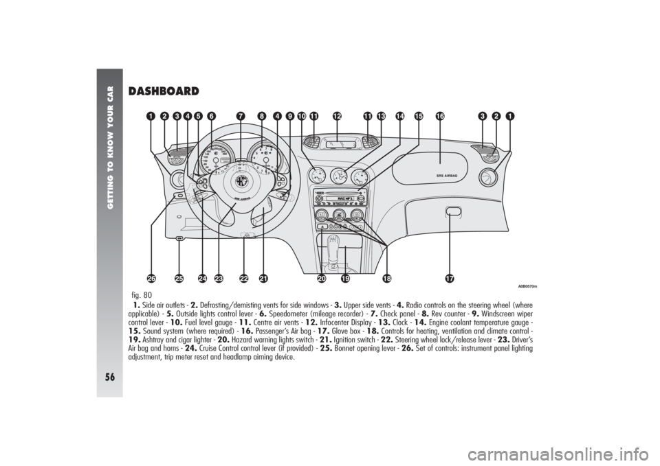
DASHBOARD1.Side air outlets - 2.Defrosting/demisting vents for side windows - 3.Upper side vents - 4.Radio controls on the steering wheel (where
applicable) - 5.Outside lights control lever - 6.Speedometer (mileage recorder) - 7.Check panel - 8.Rev counter - 9.Windscreen wiper
control lever - 10.Fuel level gauge - 11.Centre air vents - 12.Infocenter Display - 13.Clock - 14.Engine coolant temperature gauge -
15.Sound system (where required) - 16.Passenger’s Air bag - 17.Glove box - 18.Controls for heating, ventilation and climate control -
19.Ashtray and cigar lighter - 20.Hazard warning lights switch - 21.Ignition switch - 22.Steering wheel lock/release lever - 23.Driver’s
Air bag and horns - 24.Cruise Control control lever (if provided) - 25.Bonnet opening lever - 26.Set of controls: instrument panel lighting
adjustment, trip meter reset and headlamp aiming device.fig. 80
A0B0570m
Page 138 of 357
GETTING TO KNOW YOUR CAR
136
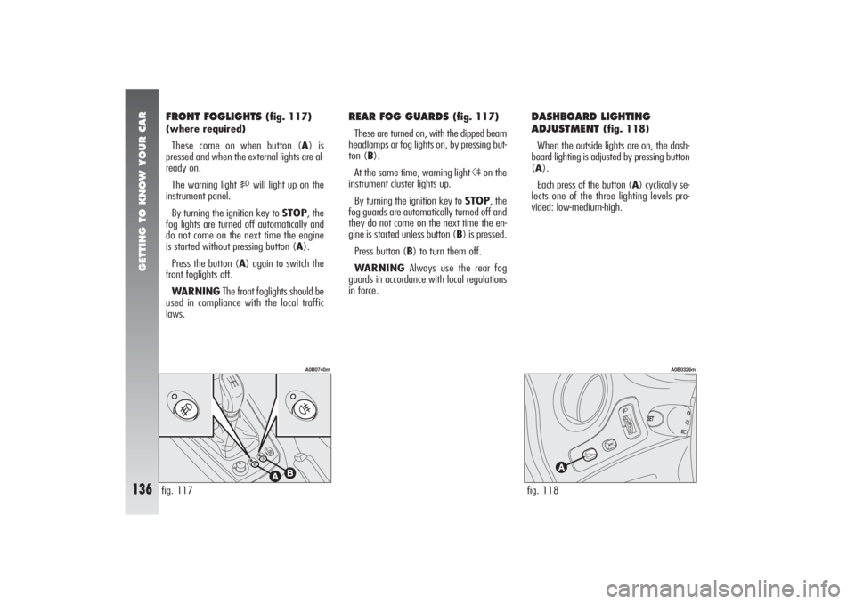
DASHBOARD LIGHTING
ADJUSTMENT
(fig. 118)
When the outside lights are on, the dash-
board lighting is adjusted by pressing button
(A).
Each press of the button (A) cyclically se-
lects one of the three lighting levels pro-
vided: low-medium-high.
FRONT FOGLIGHTS
(fig. 117)
(where required)
These come on when button (A) is
pressed and when the external lights are al-
ready on.
The warning light
5
will light up on the
instrument panel.
By turning the ignition key to STOP, the
fog lights are turned off automatically and
do not come on the next time the engine
is started without pressing button (A).
Press the button (A) again to switch the
front foglights off.
WARNINGThe front foglights should be
used in compliance with the local traffic
laws.
REAR FOG GUARDS
(fig. 117)
These are turned on, with the dipped beam
headlamps or fog lights on, by pressing but-
ton (B).
At the same time, warning light
4
on the
instrument cluster lights up.
By turning the ignition key to STOP, the
fog guards are automatically turned off and
they do not come on the next time the en-
gine is started unless button (B) is pressed.
Press button (B) to turn them off.
WARNINGAlways use the rear fog
guards in accordance with local regulations
in force.
fig. 117
A0B0740m
fig. 118
A0B0326m
Page 223 of 357

IN AN EMERGENCY
221
REPLACEMENT OF XENON
LIGHTS
(optional for versions/
markets where applicable)
Xenon lights have a very long life, there-
fore breakdowns are unlikely.
Hereafter you find the description of the
correct procedure to replace a Xenon light.– Rotate the connector (B-fig. 24) of
the Xenon lamp by a quarter of a turn
counter-clockwise, as indicated in fig. 25,
and remove it.
Dipped-beam headlamps
To replace the bulb proceed as follows:
– Unscrew the three locking screw (B-
fig. 23) and remove the protective (A)
cover.
fig. 23
A0B0348m
fig. 25
A0B0351m
fig. 24
A0B0349m
If necessary, have the sys-
tem checked and repaired
only by Alfa Romeo Authorized
Services.
WARNING
Any operation regarding
the front light units must
be carried out with the lights
turned off and the ignition key re-
moved from the ignition switch:
risk of electric discharges.
WARNING
Page 224 of 357
IN AN EMERGENCY
222
The Xenon lamp must be
handled touching only the
metallic part. If the trans-
parent bulb is touched with the fin-
gers, rub it with a clean cloth
moistened with methylated spir-
its and allow to dry before refit-
ting the bulb.
WARNINGOnce the operation has been
completed, turn dipped beam headlamps on
and check that the headlight parabola
moves when positioning the light itself. If
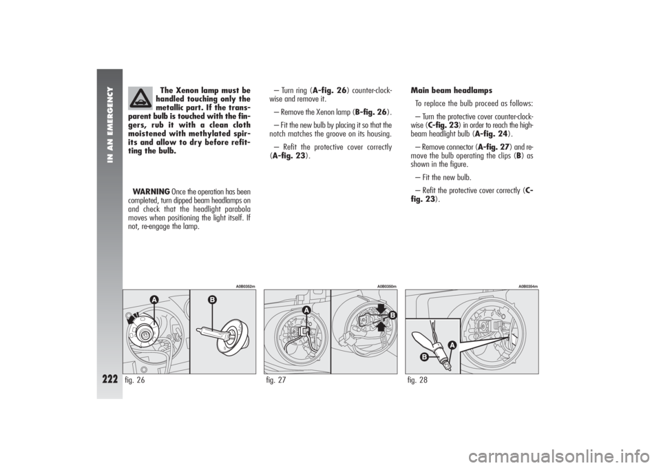
not, re-engage the lamp.– Turn ring (A-fig. 26) counter-clock-
wise and remove it.
– Remove the Xenon lamp (B-fig. 26).
– Fit the new bulb by placing it so that the
notch matches the groove on its housing.
– Refit the protective cover correctly
(A-fig. 23).Main beam headlamps
To replace the bulb proceed as follows:
– Turn the protective cover counter-clock-
wise (C-fig. 23) in order to reach the high-
beam headlight bulb (A-fig. 24).
– Remove connector (A-fig. 27) and re-
move the bulb operating the clips (B) as
shown in the figure.
– Fit the new bulb.
– Refit the protective cover correctly (C-
fig. 23).
fig. 26
A0B0352m
fig. 27
A0B0350m
fig. 28
A0B0354m
Page 226 of 357

IN AN EMERGENCY
224
– Refit the bulb holder (A-fig. 31) by
making its notches coincide with the grooves
in the headlight unit body and turn it clock-
wise.
fig. 32
A0B0222m
fig. 31
A0B0221m
DIPPED-BEAM HEADLAMPS(fig. 32)
To replace the bulb proceed as follows:
– Remove the protective cover
– Disconnect the electrical connector (A).
– Release the bulb catch (B).
– Withdraw the bulb and replace it.– Fit the new bulb making the tabs of the
metallic part coincide with the grooves in the
headlamp parabola and hook the bulb catch
(B).
– Reconnect the electrical connector (A).
– Refit the protective cover correctly.
Page 228 of 357

IN AN EMERGENCY
226
FRONT SIDELIGHTS To replace the bulb proceed as follows:
– Remove the protective cover (A-
fig. 35).
– Remove the bulb holder (B-fig. 35)
which is snap-fitted.
– Remove the bulb (C-fig. 36) from the
bulb holder, pushing lightly and turning
counter-clockwise.
– Replace the bulb and refit the bulb hold-
er (B-fig. 36) in its housing.
– Refit the protective cover correctly
(A-fig. 35).
MAIN-BEAM HEADLAMPS (fig. 37)
To replace the bulb proceed as follows:
– Remove the protective cover.
– Release the clip holding the bulb (A).
– Withdraw the power supply (B) cable
connector.
– Remove and (C) replace the bulb.
– Reconnect the power cable (B) to the
bulb.
fig. 35
A0B0217m
fig. 36
A0B0218m
– Fit the new bulb making the tabs of the
metallic part coincide with the grooves in the
headlamp parabola.
– Lock the bulb in place with the clip (A).
– Refit the protective cover correctly.fig. 37
A0B0223m
Page 238 of 357
IN AN EMERGENCY
236
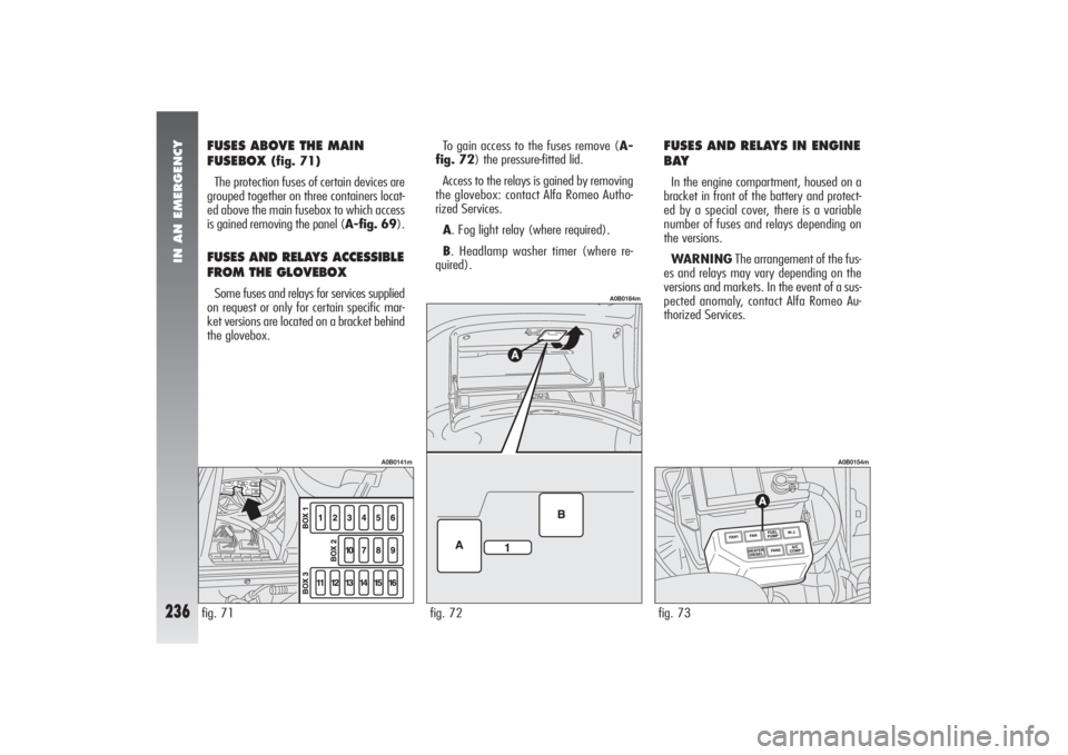
FUSES ABOVE THE MAIN
FUSEBOX
(fig. 71)
The protection fuses of certain devices are
grouped together on three containers locat-
ed above the main fusebox to which access
is gained removing the panel (A-fig. 69).
FUSES AND RELAYS ACCESSIBLE
FROM THE GLOVEBOX Some fuses and relays for services supplied
on request or only for certain specific mar-
ket versions are located on a bracket behind
the glovebox.To gain access to the fuses remove (A-
fig. 72) the pressure-fitted lid.
Access to the relays is gained by removing
the glovebox: contact Alfa Romeo Autho-
rized Services.
A. Fog light relay (where required).
B. Headlamp washer timer (where re-
quired).
FUSES AND RELAYS IN ENGINE
BAYIn the engine compartment, housed on a
bracket in front of the battery and protect-
ed by a special cover, there is a variable
number of fuses and relays depending on
the versions.
WARNINGThe arrangement of the fus-
es and relays may vary depending on the
versions and markets. In the event of a sus-
pected anomaly, contact Alfa Romeo Au-
thorized Services.fig. 73
A0B0154m
fig. 71
A0B0141m
fig. 72
A0B0184m
Page 240 of 357
IN AN EMERGENCY
238
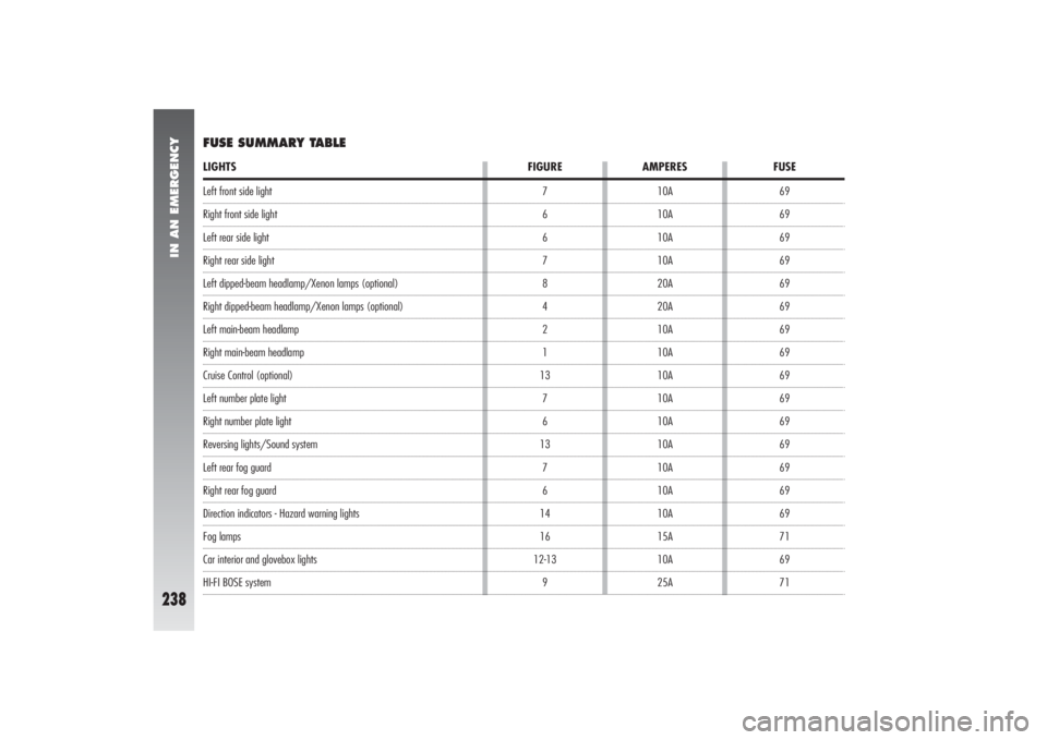
Left front side lightRight front side lightLeft rear side lightRight rear side lightLeft dipped-beam headlamp/Xenon lamps (optional)Right dipped-beam headlamp/Xenon lamps (optional)Left main-beam headlampRight main-beam headlampCruise Control (optional)Left number plate lightRight number plate lightReversing lights/Sound systemLeft rear fog guardRight rear fog guardDirection indicators - Hazard warning lightsFog lampsCar interior and glovebox lightsHI-FI BOSE system10A
10A
10A
10A
20A
20A
10A
10A
10A
10A
10A
10A
10A
10A
10A
15A
10A
25ALIGHTS FIGURE AMPERES FUSEFUSE SUMMARY TABLE
7
6
6
7
8
4
2
1
13
7
6
13
7
6
14
16
12-13
969
69
69
69
69
69
69
69
69
69
69
69
69
69
69
71
69
71
Page 241 of 357
IN AN EMERGENCY
239
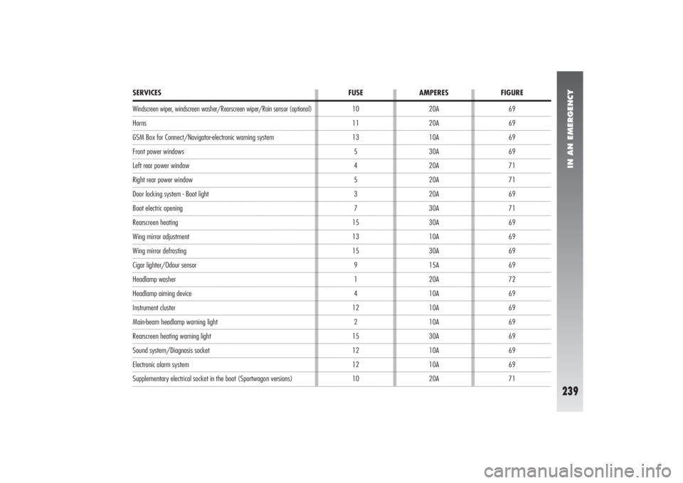
69
69
69
69
71
71
69
71
69
69
69
69
72
69
69
69
69
69
69
71 10
11
13
5
4
5
3
7
15
13
15
9
1
4
12
2
15
12
12
10
SERVICES FUSE AMPERES FIGUREWindscreen wiper, windscreen washer/Rearscreen wiper/Rain sensor (optional)HornsGSM Box for Connect/Navigator-electronic warning systemFront power windowsLeft rear power windowRight rear power windowDoor locking system - Boot lightBoot electric openingRearscreen heatingWing mirror adjustmentWing mirror defrostingCigar lighter/Odour sensorHeadlamp washerHeadlamp aiming deviceInstrument clusterMain-beam headlamp warning lightRearscreen heating warning lightSound system/Diagnosis socketElectronic alarm system Supplementary electrical socket in the boot (Sportwagon versions)20A
20A
10A
30A
20A
20A
20A
30A
30A
10A
30A
15A
20A
10A
10A
10A
30A
10A
10A
20A
Page 253 of 357
CAR MAINTENANCE
251
ADDITIONAL
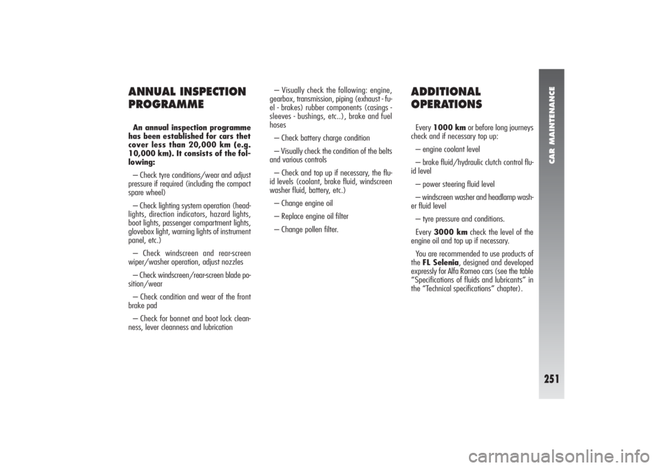
OPERATIONSEvery 1000 kmor before long journeys
check and if necessary top up:
– engine coolant level
– brake fluid/hydraulic clutch control flu-
id level
– power steering fluid level
– windscreen washer and headlamp wash-
er fluid level
– tyre pressure and conditions.
Every 3000 kmcheck the level of the
engine oil and top up if necessary.
You are recommended to use products of
the FL Selenia, designed and developed
expressly for Alfa Romeo cars (see the table
“Specifications of fluids and lubricants” in
the “Technical specifications” chapter).
ANNUAL INSPECTION
PROGRAMMEAn annual inspection programme
has been established for cars thet
cover less than 20,000 km (e.g.
10,000 km). It consists of the fol-
lowing:
– Check tyre conditions/wear and adjust
pressure if required (including the compact
spare wheel)
– Check lighting system operation (head-
lights, direction indicators, hazard lights,
boot lights, passenger compartment lights,
glovebox light, warning lights of instrument
panel, etc.)
– Check windscreen and rear-screen
wiper/washer operation, adjust nozzles
– Check windscreen/rear-screen blade po-
sition/wear
– Check condition and wear of the front
brake pad
– Check for bonnet and boot lock clean-
ness, lever cleanness and lubrication– Visually check the following: engine,
gearbox, transmission, piping (exhaust - fu-
el - brakes) rubber components (casings -
sleeves - bushings, etc..), brake and fuel
hoses
– Check battery charge condition
– Visually check the condition of the belts
and various controls
– Check and top up if necessary, the flu-
id levels (coolant, brake fluid, windscreen
washer fluid, battery, etc.)
– Change engine oil
– Replace engine oil filter
– Change pollen filter.