clock Alfa Romeo 159 2008 Owner handbook (in English)
[x] Cancel search | Manufacturer: ALFA ROMEO, Model Year: 2008, Model line: 159, Model: Alfa Romeo 159 2008Pages: 303, PDF Size: 5.18 MB
Page 100 of 303
Doorknobs can be realigned (only after
recharging the battery) as follows:
❒pressing the electronic key button Ë;
❒pressing door locking/unlocking but-
ton
q;
❒opening with the key in front door re-
volving plug;
❒pulling internal door handle.IMPORTANTAs concerns rear doors,
with child lock device on and the previ-
ously described locking active, operat-
ing the internal door handle will not
open the door but will only realign door-
knobs; to open the door pull the exter-
nal door handle. Emergency locking will
not disable central door locking/un-
locking button
q.
IMPORTANTAfter disconnecting the
battery or failing the protection fuse, the
door locking/unlocking mechanism shall
be “initialised” again, proceed as fol-
lows:
❒lock the doors;
❒press the remote control button Áor
the button
qon the central console;
❒press the remote control button Ëor
the button
qon the central console.
DOOR LOCKING WITH RUN
DOWN BATTERY
If the car battery is run down, to lock
the doors proceed as described in the
following points.
Right front door
Proceed as follows:
❒remove the protection plug on the
door;
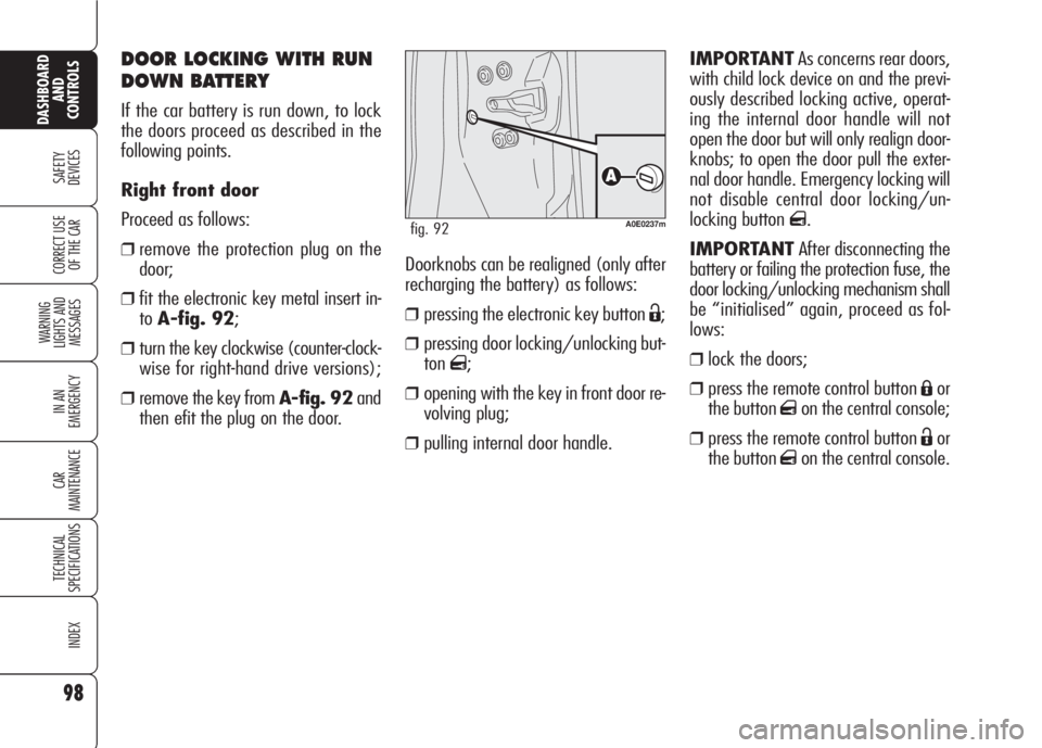
❒fit the electronic key metal insert in-
toA-fig. 92;
❒turn the key clockwise (counter-clock-
wise for right-hand drive versions);
❒remove the key from A-fig. 92and
then efit the plug on the door.
98
SAFETY
DEVICES
WARNING
LIGHTS AND
MESSAGES
IN AN
EMERGENCY
CAR
MAINTENANCE
TECHNICAL
SPECIFICATIONS
INDEX
CORRECT USE
OF THE CAR
DASHBOARD
AND
CONTROLS
A0E0237mfig. 92
Page 101 of 303
99
SAFETY
DEVICES
WARNING
LIGHTS AND
MESSAGES
IN AN
EMERGENCY
CAR
MAINTENANCE
TECHNICAL
SPECIFICATIONS
INDEX
CORRECT USE
OF THE CAR
DASHBOARD
AND
CONTROLS
IMPORTANTIn the event the anti-
crushing function is activated 5 times in
only 1 minute or in the event of a fail-
ure, the system will automatically enter
the “recovery” mode (self-protection).
This condition is pointed out by the fact
that, in the closing stroke, the windows
goes up in jerks.
In this case it is necessary to carry out
system restore procedure as follows:
❒open the windows;
or
❒remove and then refit the key into the
ignition device.
If no malfunction is present, the window
returns to its normal operation automat-
ically. In the event of a failure see section
“Warning lights and messages”.Windows and sunroof
opening/closing by the
electronic key
(where provided)
By the metal insert of the key
On all versions:
❒turning clockwise the metal insert of
the key into the driver's door re-
volving plug will open all the win-
dows and the sunroof (where pro-
vided) at the same time.
❒turning counterclockwise the metal
insert of the key into the driver's
door revolving plug will close all the
windows and the sunroof (where
provided) at the same time.
By remote control
On all versions, keep button
Ëpressed
for over 2 seconds to open all the win-
dows and the sunroof (where provided)
at the same time.
POWER WINDOWS
Versions with 2 front power windows
are fitted with automatic window open-
ing/closing only on the driver’s side.
Versions with 4 power windows are fit-
ted with automatic window opening/
closing on all doors. For versions/mar-
kets where applicable the passenger
side electrical window and the rear elec-
trical windows are provided with a safe-
ty system with anti-crushing seal able to
recognize the eventual presence of an
obstacle during the closing movement
of the window; upon verification of this
event the system interrupts and imme-
diately inverts the run of the window.
This system is particularly useful when
children operate the windows inadver-
tently and make it possible to close/
open (where provided) the windows us-
ing the remote control when leaving the
car.
The system complies
with the forthcoming
Standard 2000/4/ EC
concerning the safety of pas-
sengers leaning out of the pas-
senger compartment.
Page 197 of 303

195
SAFETY
DEVICES
WARNING
LIGHTS AND
MESSAGES
CAR
MAINTENANCE
TECHNICAL
SPECIFICATIONS
INDEX
CORRECT USE
OF THE CAR
DASHBOARD
AND
CONTROLS
IN AN
EMERGENCY
CYLINDER REPLACEMENT
PROCEDURE
To replace the cylinder proceed as fol-
lows:
❒disconnect connection A-fig. 23
and hose B;
❒turn counter-clockwise the cylinder to
replace and raise it;
❒fit the new cylinder and turn it clock-
wise;
❒refit connection Aor connect hose
Binto its seat.
A0E0047mfig. 23
Inform other people
driving the car that the
tyre has been repaired using
the quick tyre kit. Hand the
sticker to the personnel that
will carry out restoring oper-
ations.
WARNING
Page 199 of 303

197
SAFETY
DEVICES
WARNING
LIGHTS AND
MESSAGES
CAR
MAINTENANCE
TECHNICAL
SPECIFICATIONS
INDEX
CORRECT USE
OF THE CAR
DASHBOARD
AND
CONTROLS
IN AN
EMERGENCY
B Bayonet type bulbs:press the
bulb, turn counter-clockwise to re-
move this type of bulb from its
holder.
C Tubular bulbs:release them
from their contacts to remove.D-E Halogen bulbs: to remove the
bulb, release the clip holding the
bulb in place.
F Gas-discharge bulbs
(Bixenon).TYPES OF BULBS fig. 24
Various types of bulbs are fitted to your
car:
A Glass bulbs: clipped into posi-
tion. Pull to remove.
A0E0117mfig. 24
Page 201 of 303
199
SAFETY
DEVICES
WARNING
LIGHTS AND
MESSAGES
CAR
MAINTENANCE
TECHNICAL
SPECIFICATIONS
INDEX
CORRECT USE
OF THE CAR
DASHBOARD
AND
CONTROLS
IN AN
EMERGENCYMain beam headlights
(halogen bulbs)
To change the bulb, proceed as follows:
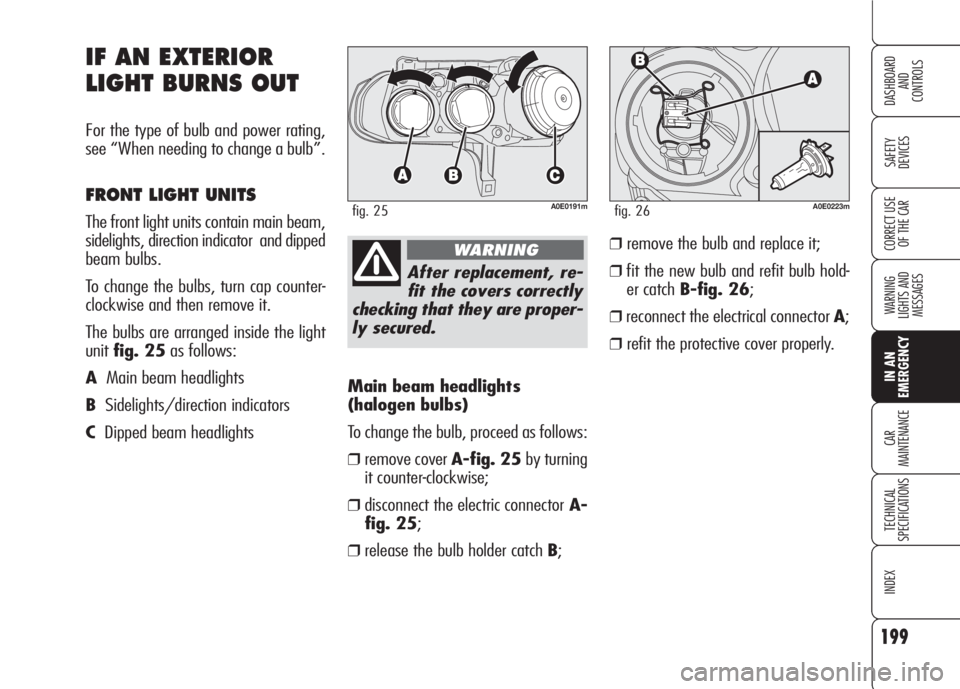
❒remove cover A-fig. 25by turning
it counter-clockwise;
❒disconnect the electric connectorA-
fig. 25;
❒release the bulb holder catch B;
IF AN EXTERIOR
LIGHT BURNS OUT
For the type of bulb and power rating,
see “When needing to change a bulb”.
FRONT LIGHT UNITS
The front light units contain main beam,
sidelights, direction indicator and dipped
beam bulbs.
To change the bulbs, turn cap counter-
clockwise and then remove it.
The bulbs are arranged inside the light
unitfig. 25as follows:
AMain beam headlights
BSidelights/direction indicators
CDipped beam headlights
A0E0191mfig. 25
After replacement, re-
fit the covers correctly
checking that they are proper-
ly secured.
WARNING
A0E0223mfig. 26
❒remove the bulb and replace it;
❒fit the new bulb and refit bulb hold-
er catch B-fig. 26;
❒reconnect the electrical connector A;
❒refit the protective cover properly.
Page 202 of 303
200
SAFETY
DEVICES
WARNING
LIGHTS AND
MESSAGES
CAR
MAINTENANCE
TECHNICAL
SPECIFICATIONS
INDEX
CORRECT USE
OF THE CAR
DASHBOARD
AND
CONTROLS
IN AN
EMERGENCY
Sidelights
To change the bulb, proceed as follows:
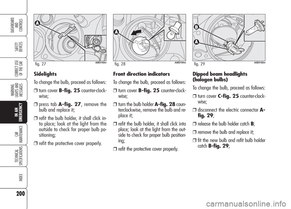
❒turn cover B-fig. 25counter-clock-
wise;
❒press tab A-fig. 27, remove the
bulb and replace it;
❒refit the bulb holder, it shall click in-
to place; look at the light from the
outside to check for proper bulb po-
sitioning;
❒refit the protective cover properly.
A0E0193mfig. 27A0E0194mfig. 28A0E0192mfig. 29
Front direction indicators
To change the bulb, proceed as follows:
❒turn cover B-fig. 25counter-clock-
wise;
❒turn the bulb holder A-fig. 28coun-
terclockwise, remove the bulb and re-
place it;
❒refit the bulb holder, it shall click into
place; look at the light from the out-
side to check for proper bulb position-
ing;
❒refit the protective cover properly.Dipped beam headlights
(halogen bulbs)
To change the bulb, proceed as follows:
❒turn cover C-fig. 25counter-clock-
wise;
❒disconnect the electric connector A-
fig. 29;
❒release the bulb holder catch B;
❒remove the bulb and replace it;
❒fit the new bulb and refit bulb holder
catchB-fig. 29;
Page 203 of 303
201
SAFETY
DEVICES
WARNING
LIGHTS AND
MESSAGES
CAR
MAINTENANCE
TECHNICAL
SPECIFICATIONS
INDEX
CORRECT USE
OF THE CAR
DASHBOARD
AND
CONTROLS
IN AN
EMERGENCY
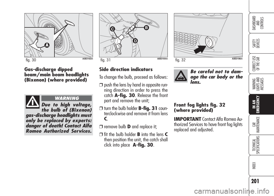
Side direction indicators
To change the bulb, proceed as follows:
❒push the lens by hand in opposite run-
ning direction in order to press the
catchA-fig. 30. Release the front
part and remove the unit;
❒turn the bulb holder B-fig. 31coun-
terclockwise and remove it from lens
C.
❒remove bulb Dand replace it;
❒fit the bulb holder Binto the lens C
then position the unit, the catch shall
click into place A-fig. 30.Front fog lights fig. 32
(where provided)
IMPORTANTContact Alfa Romeo Au-
thorized Services to have front fog lights
replaced and adjusted.
A0E0163mfig. 30A0E0164mfig. 31
Be careful not to dam-
age the car body or the
lens.
A0E0196mfig. 32
Due to high voltage,
the bulb of (Bixenon)
gas-discharge headlights must
only be replaced by experts:
danger of death! Contact Alfa
Romeo Authorized Services.
WARNING
Gas-discharge dipped
beam/main beam headlights
(Bixenon) (where provided)
Page 204 of 303

202
SAFETY
DEVICES
WARNING
LIGHTS AND
MESSAGES
CAR
MAINTENANCE
TECHNICAL
SPECIFICATIONS
INDEX
CORRECT USE
OF THE CAR
DASHBOARD
AND
CONTROLS
IN AN
EMERGENCY
Reversing light/rear fog
lights
To replace the bulbs proceed as follows:
❒open the tailgate;
❒turn deviceA-fig. 33 to open lid
B;
❒lower the lid and remove the bulb
holder unit by pressing the retaining tabs
C-fig. 34;
❒remove and replace the burnt-out
bulb by pressing it slightly and turn-
ing it counterclockwise fig. 35:
D:reversing light bulb on passenger
side (or right side);
D:reversing light bulb on driver side (or
left side)
❒refit the bulb holder unit securing it
properly using the retaining tabs C-
fig. 34;
❒close lidB-fig. 33.
REAR LIGHT UNITS
Rear light units contain: reversing light,
rear fog light, direction indicators, tail-
lights, number plate lights, brake light
and third brake light bulbs.
A0E0165mfig. 33A0E0166mfig. 34A0E0167mfig. 35
Page 205 of 303

203
SAFETY
DEVICES
WARNING
LIGHTS AND
MESSAGES
CAR
MAINTENANCE
TECHNICAL
SPECIFICATIONS
INDEX
CORRECT USE
OF THE CAR
DASHBOARD
AND
CONTROLS
IN AN
EMERGENCY
Direction indicators/
Taillights/Brake lights
To replace the bulbs proceed as follows:
❒open the tailgate;
❒loosen screw A-fig. 37and remove
the protection cover B;
❒remove the bulb holder unit C-
fig. 38by pressing the retaining
tabsD.
A0E0170mfig. 37
Taillight bulb on tailgate
To replace the bulbs proceed as follows:
❒open the tailgate;
❒turn deviceA-fig. 33 to open lid
B;
❒lower the lid and remove the bulb
holder unit by pressing the retaining
tabsC-fig. 34;
A0E0229mfig. 36
❒remove and replace the burnt-out
bulb by pressing it slightly and turn-
ing it counterclockwisefig. 36:
D: taillight bulb on right/left headlight
❒refit the bulb holder unit securing it
properly using the retaining tabs C-
fig. 34;
❒close lidB-fig. 33.
A0E0040mfig. 38
Page 206 of 303

204
SAFETY
DEVICES
WARNING
LIGHTS AND
MESSAGES
CAR
MAINTENANCE
TECHNICAL
SPECIFICATIONS
INDEX
CORRECT USE
OF THE CAR
DASHBOARD
AND
CONTROLS
IN AN
EMERGENCY
Additional brake light
(third stop)
Contact Alfa Romeo Authorized Services
to have the third brake light replaced. ❒remove and replace the burnt-out
bulb by pressing it slightly and turn-
ing it counter-clockwisefig. 39:
Etaillight/brake light bulb;
Fdirection indicator bulb.
❒refit the bulb holder unit securing it
properly using the retaining tabs D-
fig. 38;
❒refit the protection cover B-fig. 37
and tighten screw A.Number plate light
To replace the bulbs proceed as follows:
❒operate with a flat blade screwdriver pro-
tected by a soft cloth on device A-fig.
40to remove the light unit B;
❒remove the bulb holderC-fig. 41by
turning it slightly and replace the snap-
fitted bulb D.
A0E0041mfig. 39A0E0168mfig. 40A0E0169mfig. 41