boot Alfa Romeo 166 2007 Owner handbook (in English)
[x] Cancel search | Manufacturer: ALFA ROMEO, Model Year: 2007, Model line: 166, Model: Alfa Romeo 166 2007Pages: 272, PDF Size: 4.17 MB
Page 179 of 272

178
– Lower the lid (A-fig. 56) of the
boot trim corresponding with the light
concerned and remove the bulb holder
unit (B-fig. 57) releasing the retainer
catch (C).
– Remove and replace the bulb con-
cerned (spherical with bayonet coupling)
pushing gently and turning counter-clock-
wise (fig. 58):
(D) Reversing light bulb
(E) Rear fog guard bulb
(F) Sidelight bulb.GUARDS AND SIDELIGHTS
To replace the bulbs (Type B, 21W re-
versing light and rear fog guard, 5W side-
light):
– Open the boot.– Re-insert the bulb holder unit fasten-
ing it correctly in place using the retainer
catches (C-fig. 57).
– Shut the trim lid.
P4C00057611PGSm
fig. 56
606PGSm
fig. 57 fig. 58
607PGSm
Page 180 of 272
179
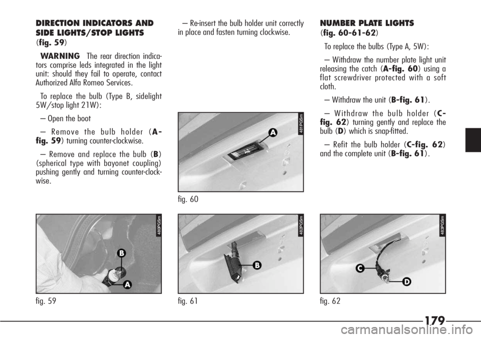
DIRECTION INDICATORS AND
SIDE LIGHTS/STOP LIGHTS
(fig. 59)
WARNING The rear direction indica-
tors comprise leds integrated in the light
unit: should they fail to operate, contact
Authorized Alfa Romeo Services.
To replace the bulb (Type B, sidelight
5W/stop light 21W):
– Open the boot
– Remove the bulb holder (A-
fig. 59) turning counter-clockwise.
– Remove and replace the bulb (B)
(spherical type with bayonet coupling)
pushing gently and turning counter-clock-
wise.– Re-insert the bulb holder unit correctly
in place and fasten turning clockwise.
NUMBER PLATE LIGHTS
(fig. 60-61-62)
To replace the bulbs (Type A, 5W):
– Withdraw the number plate light unit
releasing the catch (A-fig. 60) using a
flat screwdriver protected with a soft
cloth.
– Withdraw the unit (B-fig. 61).
– Withdraw the bulb holder (C-
fig. 62) turning gently and replace the
bulb (D) which is snap-fitted.
– Refit the bulb holder (C-fig. 62)
and the complete unit (B-fig. 61).
481PGSm
fig. 60
482PGSm
fig. 61
483PGSm
fig. 62
480PGSm
fig. 59
Page 191 of 272
190
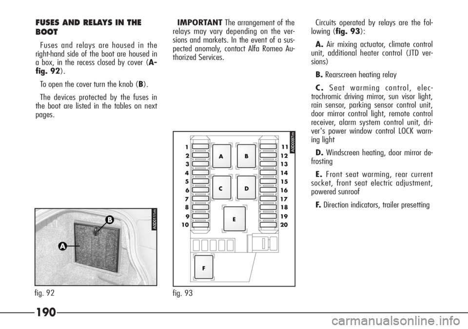
FUSES AND RELAYS IN THE
BOOT
Fuses and relays are housed in the
right-hand side of the boot are housed in
a box, in the recess closed by cover (A-
fig. 92).
To open the cover turn the knob (B).
The devices protected by the fuses in
the boot are listed in the tables on next
pages.IMPORTANTThe arrangement of the
relays may vary depending on the ver-
sions and markets. In the event of a sus-
pected anomaly, contact Alfa Romeo Au-
thorized Services.Circuits operated by relays are the fol-
lowing (fig. 93):
A.Air mixing actuator, climate control
unit, additional heater control (JTD ver-
sions)
B.Rearscreen heating relay
C.Seat warming control, elec-
trochromic driving mirror, sun visor light,
rain sensor, parking sensor control unit,
door mirror control light, remote control
receiver, alarm system control unit, dri-
ver's power window control LOCK warn-
ing light
D.Windscreen heating, door mirror de-
frosting
E.Front seat warming, rear current
socket, front seat electric adjustment,
powered sunroof
F.Direction indicators, trailer presetting
518PGS
fig. 93
A0D0097m
A0D0111m
fig. 92
Page 194 of 272

193
System/Component Fuse no. Ampere Location
Rearscreen heating 1 30A fig. 93
Relay coil T21, T22, T23 (boot box) 3 5A fig. 86
Relay coil T24 (boot box) 5 10A fig. 86
Remote control receiver 15 10A fig. 93
Sound amplifier 20 25A fig. 93
Sound system 4 15A fig. 86
Sound system controls on steering wheel 5 10Afig. 86
Starter motor 1 30A fig. 89
Trailer presetting 12 10A fig. 93
Windscreen heating 7 15A fig. 93
Windscreen wiper 14 25A fig. 86
System/Component Fuse no. Ampere Location
Navigator 18 5A fig. 86
Parking sensors (control unit) 15 10A fig. 93
Power windows (driver's control
LOCK warning light) 15 10A fig. 93
Powered sunroof 10 20A fig. 93
Presetting 4 – fig. 93
11 – fig. 93
Rain sensor 15 10A fig. 93
Rear current socket 16 20A fig. 93
Rear LH power window (ABI control unit) 14 20Afig. 93
Rear RH power window (ABI control unit) 17 20Afig. 93
Page 195 of 272
194 IN THE EVENT
OF A FLAT BATTERY
STARTING WITH AN
AUXILIARY BATTERY
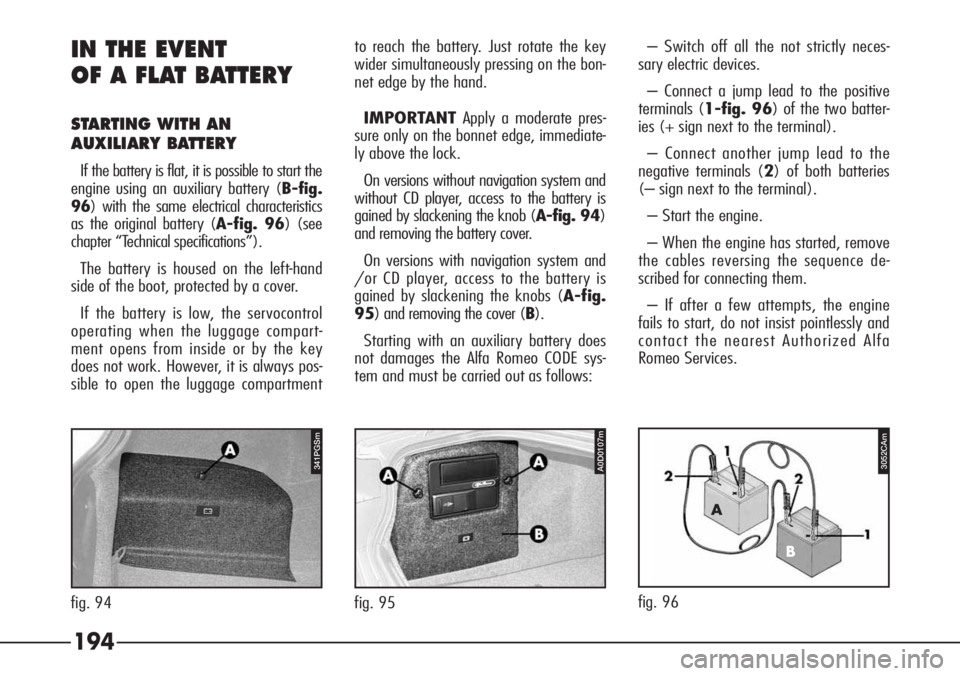
If the battery is flat, it is possible to start the
engine using an auxiliary battery (B-fig.
96) with the same electrical characteristics
as the original battery (A-fig. 96) (see
chapter “Technical specifications”).
The battery is housed on the left-hand
side of the boot, protected by a cover.
If the battery is low, the servocontrol
operating when the luggage compart-
ment opens from inside or by the key
does not work. However, it is always pos-
sible to open the luggage compartmentto reach the battery. Just rotate the key
wider simultaneously pressing on the bon-
net edge by the hand.
IMPORTANTApply a moderate pres-
sure only on the bonnet edge, immediate-
ly above the lock.
On versions without navigation system and
without CD player, access to the battery is
gained by slackening the knob (A-fig. 94)
and removing the battery cover.
On versions with navigation system and
/or CD player, access to the battery is
gained by slackening the knobs (A-fig.
95) and removing the cover (B).
Starting with an auxiliary battery does
not damages the Alfa Romeo CODE sys-
tem and must be carried out as follows:– Switch off all the not strictly neces-
sary electric devices.
– Connect a jump lead to the positive
terminals (1-fig. 96) of the two batter-
ies (+ sign next to the terminal).
– Connect another jump lead to the
negative terminals (2) of both batteries
(– sign next to the terminal).
– Start the engine.
– When the engine has started, remove
the cables reversing the sequence de-
scribed for connecting them.
– If after a few attempts, the engine
fails to start, do not insist pointlessly and
contact the nearest Authorized Alfa
Romeo Services.
fig. 96
A
B
fig. 94
A0D0107m3052CAm
fig. 95
341PGSm
Page 197 of 272

196 IF THE VEHICLE
IS TO BE TOWED
Towing the vehicle (fig. 97)
The rings for towing the vehicle are
housed in the right and left lower part of
the underbody.
Towing another vehicle
(fig. 98-99)
The tow ring supplied with the vehicle is
housed in the tool container under the
boot mat.To install the tow ring, proceed as fol-
lows:
– Take the tow ring from the tool con-
tainer.
– Remove the cover (A-fig. 98) s-
nap-fitted on the rear bumper as follows:
Take the screwdriver from the tool con-
tainer in the boot, under the trim.Using the flat bladed side protected with
a soft cloth, insert the screwdriver on the
upper part of the cap and press gently to
prise the catch from its housing.
– Firmly screw the ring (B-fig. 99) in
its housing.
Make sure that the tow
ring is firmly tightened (it
must be turned about 8 times in its
threaded housing); carefully clean
the threaded housing before tight-
ening the ring.
WARNING
448PGS
fig. 97
A0D0089mA0D0088m
fig. 98 fig. 99
A0D0090m
Page 205 of 272
204
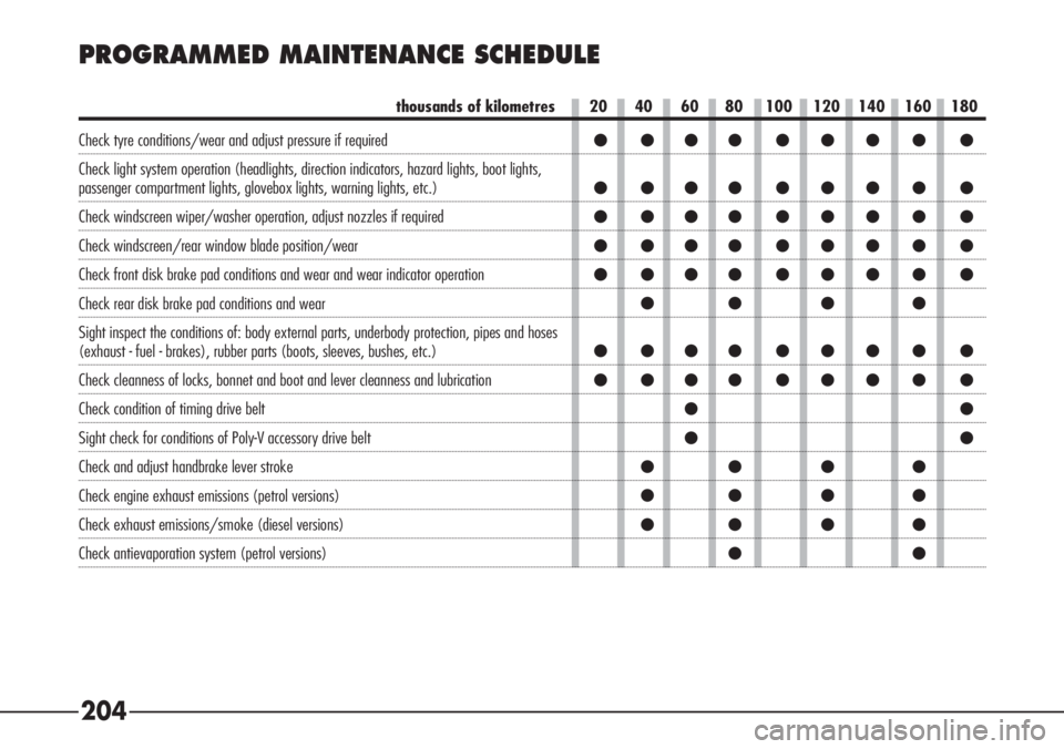
PROGRAMMED MAINTENANCE SCHEDULE
thousands of kilometres
Check tyre conditions/wear and adjust pressure if required
Check light system operation (headlights, direction indicators, hazard lights, boot lights,
passenger compartment lights, glovebox lights, warning lights, etc.)
Check windscreen wiper/washer operation, adjust nozzles if required
Check windscreen/rear window blade position/wear
Check front disk brake pad conditions and wear and wear indicator operation
Check rear disk brake pad conditions and wear
Sight inspect the conditions of: body external parts, underbody protection, pipes and hoses
(exhaust - fuel - brakes), rubber parts (boots, sleeves, bushes, etc.)
Check cleanness of locks, bonnet and boot and lever cleanness and lubrication
Check condition of timing drive belt
Sight check for conditions of Poly-V accessory drive belt
Check and adjust handbrake lever stroke
Check engine exhaust emissions (petrol versions)
Check exhaust emissions/smoke (diesel versions)
Check antievaporation system (petrol versions)20 40 60 80 100 120 140 160 180
● ●●● ● ● ● ● ●
● ●●● ● ● ● ● ●
● ●●● ● ● ● ● ●
● ●●● ● ● ● ● ●
● ●●● ● ● ● ● ●
●● ● ●
● ●●● ● ● ● ● ●
● ●●● ● ● ● ● ●
●●
●●
●● ● ●
●● ● ●
●● ● ●
●●
Page 207 of 272
206 ANNUAL INSPECTION
PLAN
An annual inspection plan has
been established for cars that cov-
er less than 20,000 km a year
(e.g. 10,000 km). It consists of
the following:
– Checking the condition/wear of tyres,
and adjusting pressure (including the com-
pact spare wheel, where applicable).
– Checking the lighting system (head-
lights, turn indicators, hazard warning
lights, boot light, passenger compart-
ment, warning lights of instrument panel,
etc.).
– Checking the working order of the
windscreen wiper-washer and adjusting
the nozzles.
– Checking the positioning/wear of the
windscreen wipers.
– Checking the condition and wear of
the front brake pad.– Sight inspect the conditions of: en-
gine, gearbox, transmission, pipes and
hoses (exhaust - fuel - brakes), rubber
parts (boots, sleeves, bushes, etc.).
– Check for bonnet and boot lock clean-
ness, lever cleanness and lubrication.
– Check battery charge and fluid level
(electrolyte).
– Visually checking the condition of the
belts and various controls.
– Checking and topping up, if neces-
sary, the level of liquids (coolant, brake
fluid, windscreen washer fluid, battery
etc.).
– Change engine oil and oil filter, if re-
quired.
– Check and replace pollen filter, if re-
quired.
– Check and replace air cleaner, if re-
quired.
ADDITIONAL OPERATIONS
Every 1000 kmor before long jour-
neys check and if necessary top up:
– the engine coolant fluid level
– brake fluid/hydraulic clutch control
fluid level
– power steering fluid level
– windscreen washer and headlamp
washer fluid level
– tyre pressure and conditions.
– check light system operation (head-
lights, direction indicators, hazard lights,
etc.).
– check windscreen wiper/washer op-
eration and windscreen/rear window
blade position/wear.
Every 3000 kmcheck the level of
the engine oil and top up if necessary.
Every 5000 km(only for fuel oil en-
gines): drain the condensation water
from the filter. You are recommended to
use products of the FL Selenia, de-
signed and developed expressly for Alfa
Romeo cars (see the table “Fluids and lu-
bricants” in the Technical specifications”
chapter).
Page 220 of 272
219
DUST/POLLEN FILTER
The filter mechanically/electrostatically
filters the air provided that the windows
are shut.
The dust/pollen filter should be checked
over once a year by Alfa Romeo Autho-
rized Service station preferably at the be-
ginning of the summer.
If the vehicle is habitually driven in
cities, motorways or on dusty roads the
system should be checked over more of-
ten than specified in the Programmed
Maintenance Schedule.
IMPORTANT If the filter is not re-
placed the efficiency of the climate con-
trol system may be seriously compro-
mised.
DIESEL FILTER
DRAINING CONDENSATION
WATER
BATTERY
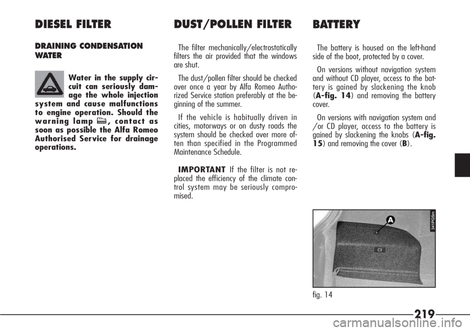
The battery is housed on the left-hand
side of the boot, protected by a cover.
On versions without navigation system
and without CD player, access to the bat-
tery is gained by slackening the knob
(A-fig. 14) and removing the battery
cover.
On versions with navigation system and
/or CD player, access to the battery is
gained by slackening the knobs (A-fig.
15) and removing the cover (B). Water in the supply cir-
cuit can seriously dam-
age the whole injection
system and cause malfunctions
to engine operation. Should the
warning lamp c, contact as
soon as possible the Alfa Romeo
Authorised Service for drainage
operations.
fig. 14
341PGSm
Page 223 of 272
222
– Before doing any work on the electric
system, disconnect the battery negative
terminal.
If after purchasing the car, you wish to
install electrical accessories which need a
permanent electrical supply (alarm,
hands-free phone, radio-navigator with
satellite anti-theft function, etc.) contact
Authorised Alfa Romeo Services whose
qualified personnel, in addition to sug-
gesting the most suitable devices from
Lineaccessori will be able to evaluate the
total electrical absorption, checking
whether the car’s electric system is able
to support the load required or whether a
battery with higher capacity is necessary.
In fact, these devices continue to absorb
current with the ignition key off (car
parked, engine off) and may gradually
drain the battery. IMPORTANT A battery kept at below
50% of its capacity is damaged by sul-
phation, the capacity is reduced and start-
ing is difficult, there is also more possibili-
ty of freezing (this can occur at –10°C).
In the event of a prolonged stop, refer to
“Vehicle inactivity”.
USEFUL HINTS TO EXTEND
THE LIFE OF YOUR BATTERY
To avoid quickly draining the battery
and to preserve its operating conditions
over the course of time, carefully follow
the instructions below.
– The terminals must always be tight-
ened.
– As far as possible avoid keeping ser-
vices on for a long time with the engine
stopped (radio, hazard warning lights,
parking lights, etc.).
– When leaving the vehicle parked in a
garage, make sure that the doors, bon-
net, boot and interior lids are properly
shut to prevent lights from staying on.
The fluid contained in the
battery is poisonous and
corrosive. Avoid contact with the
skin or eyes. The battery should be
charged in a ventilated place away
from naked flames or possible
sources of sparks: danger of ex-
plosion and fire.
WARNING
Never attempt to charge
a frozen battery before
thawing it, the danger of explosion
exists. If it has frozen, always
check that the inside elements are
not broken (risk of short circuit)
and that the body is not cracked,
with the risk of acid coming out
which is poisonous and corrosive.
WARNING