oil Alfa Romeo Brera/Spider 2006 Owner handbook (in English)
[x] Cancel search | Manufacturer: ALFA ROMEO, Model Year: 2006, Model line: Brera/Spider, Model: Alfa Romeo Brera/Spider 2006Pages: 267, PDF Size: 7.21 MB
Page 9 of 267
7
SAFETY
DEVICES
WARNING
LIGHTS AND
MESSAGES
IN AN
EMERGENCY
CAR
MAINTENANCE
TECHNICAL
SPECIFICATIONS
INDEX
DASHBOARD
AND
CONTROLS
CORRECT USE
OF THE CAR
DASHBOARD
A0F0056mfig. 1
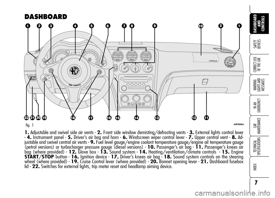
1.Adjustable and swivel side air vents - 2. Front side window demisting/defrosting vents - 3.External lights control lever
- 4.Instrument panel - 5.Driver’s air bag and horn - 6.Windscreen wiper control lever - 7.Upper central vent - 8.Ad-
justable and swivel central air vents - 9.Fuel level gauge/engine coolant temperature gauge/engine oil temperature gauge
(petrol versions) or turbocharger pressure gauge (diesel versions) - 10.Passenger’s air bag - 11.Passenger’s knees air
bag (where provided) - 12.Glove box - 13.Sound system - 14.Heating/ventilation/climate controls - 15. Engine
START/STOPbutton - 16.Ignition device - 17.Driver’s knees air bag - 18.Sound system controls on the steering
wheel (where provided) - 19.Cruise Control lever (where provided) - 20.Bonnet opening lever - 21.Dashboard fusebox
lid - 22.Switches for external lights, trip meter reset and headlamp aiming device.
Page 26 of 267
24
SAFETY
DEVICES
WARNING
LIGHTS AND
MESSAGES
IN AN
EMERGENCY
CAR
MAINTENANCE
TECHNICAL
SPECIFICATIONS
INDEX
DASHBOARD
AND
CONTROLS
CORRECT USE
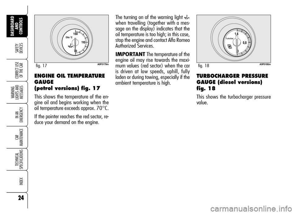
OF THE CARENGINE OIL TEMPERATURE
GAUGE
(petrol versions) fig. 17
This shows the temperature of the en-
gine oil and begins working when the
oil temperature exceeds approx. 70°C.
If the pointer reaches the red sector, re-
duce your demand on the engine.
A0F0179mfig. 17
The turning on of the warning light `
when travelling (together with a mes-
sage on the display) indicates that the
oil temperature is too high; in this case,
stop the engine and contact Alfa Romeo
Authorized Services.
IMPORTANTThe temperature of the
engine oil may rise towards the maxi-
mum values (red sector) when the car
is driven at low speeds, uphill, fully
laden or during towing, especially if the
ambient temperature is high.
A0F0180mfig. 18
TURBOCHARGER PRESSURE
GAUGE (diesel versions)
fig. 18
This shows the turbocharger pressure
value.
Page 27 of 267

25
SAFETY
DEVICES
WARNING
LIGHTS AND
MESSAGES
IN AN
EMERGENCY
CAR
MAINTENANCE
TECHNICAL
SPECIFICATIONS
INDEX
DASHBOARD
AND
CONTROLS
CORRECT USE
OF THE CAR
AUTOMATIC INSTRUMENT
PANEL LIGHT DIMMER
To give max. visibility and comfort un-
der whatever driving conditions (e.g.:
lights on in daylight, tunnels, etc…), the
speedometer is fitted with a sensor for
adjusting automatically, after fitting the
electronic key into the ignition device and
pressing button START/STOP, the
light intensity of the instrument panel dis-
play, sound system display, climate con-
trol system display, radionavigation sys-
tem display (where provided), and in-
struments (i.e.: fuel level gauge, engine
oil temperature gauge for petrol versions
or turbocharger pressure gauge for diesel
versions, and engine coolant temperature
gauge).
TRIP METER RESET fig. 19
To reset the trip meter, keep button A
pressed for a few seconds.
MANUAL INSTRUMENT
PANEL LIGHT DIMMER
With this function it is possible to adjust
on 8 levels the light intensity of the indi-
cations given on the instrument panel dis-
play, sound system display, climate con-
trol system display, radionavigation sys-
tem display (where provided), and in-
struments (i.e.: fuel level gauge, engine
oil temperature gauge for petrol versions
or turbocharger pressure gauge for diesel
versions, and engine coolant temperature
gauge).
To increase light intensity press briefly
button +on the left-hand stalk, to re-
duce it press button –: the display will
show an indication and a figure corre-
sponding to the current light intensity
level. This screen will be displayed for
a few seconds and then it will go off.
A0F0072mfig. 19
Page 28 of 267
26
SAFETY
DEVICES
WARNING
LIGHTS AND
MESSAGES
IN AN
EMERGENCY
CAR
MAINTENANCE
TECHNICAL
SPECIFICATIONS
INDEX
DASHBOARD
AND
CONTROLS
CORRECT USE
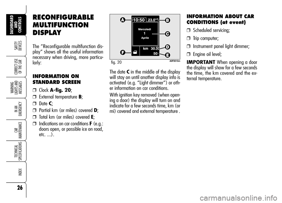
OF THE CARThe date Cin the middle of the display
will stay on until another display info is
activated (e.g. “Light dimmer”) or oth-
er information on car conditions.
With ignition key removed (when open-
ing a door) the display will turn on and
indicate for a few seconds time, km (or
mi) covered and external temperature .
INFORMATION ABOUT CAR
CONDITIONS (at event)
❒Scheduled servicing;
❒Trip computer;
❒Instrument panel light dimmer;
❒Engine oil level;
IMPORTANTWhen opening a door
the display will show for a few seconds
the time, the km covered and the ex-
ternal temperature.
RECONFIGURABLE
MULTIFUNCTION
DISPLAY
The “Reconfigurable multifunction dis-
play” shows all the useful information
necessary when driving, more particu-
larly:
INFORMATION ON
STANDARD SCREEN
❒Clock A-fig. 20;
❒External temperature B;
❒Date C;
❒Partial km (or miles) covered D;
❒Total km (or miles) covered E;
❒Indications on car conditions F (e.g.:
doors open, or possible ice on road,
etc. ...).
A0F0015mfig. 20
Page 30 of 267
28
SAFETY
DEVICES
WARNING
LIGHTS AND
MESSAGES
IN AN
EMERGENCY
CAR
MAINTENANCE
TECHNICAL
SPECIFICATIONS
INDEX
DASHBOARD
AND
CONTROLS
CORRECT USE
OF THE CAR
Selecting “Date” and “Clock”:
❒briefly press button MENUto select
the first value to change (e.g. hours
/minutes or year /month /day);
❒operate buttons +or –(by single
press) to select the new setting;
❒briefly press button MENUto store
new setting and go back to the pre-
viously selected option of the main
menu, if this is the last one you will
go back to the previously selected
option of the main menu.
ENGINE OIL
LEVEL INDICATION
Fitting the electronic key into the igni-
tion device, the display will show for a
few seconds the engine oil level. At this
stage, to clear this indication and to go
to next screen, press button MENU.
Low/excessive oil level will be indicat-
ed by a dedicated warning message on
the display.
IMPORTANT Check the proper en-
gine oil level on the dipstick (see para-
graph “Checking levels” in section “Car
maintenance”).
IMPORTANTProper engine oil level
shall be checked with the car on level
ground.
IMPORTANTFor proper oil level in-
dication, after fitting the key, wait for
about 2 seconds before starting the en-
gine.
IMPORTANTEngine oil level could in-
crease after a long stop. Selecting an option of the main
menu with submenu:❒briefly press button MENUto dis-
play the first submenu option;
❒operate buttons +or –(by single
press) to scroll all submenu options;
❒briefly press button MENUto select
the displayed submenu option and
to enter the corresponding setup
menu;
❒ operate buttons +or –(by single
press) to select the new setting of this
submenu option;
❒ briefly press button MENUto store
the new setting and go back to the
previously selected submenu option.
Page 50 of 267
48
SAFETY
DEVICES
WARNING
LIGHTS AND
MESSAGES
IN AN
EMERGENCY
CAR
MAINTENANCE
TECHNICAL
SPECIFICATIONS
INDEX
DASHBOARD
AND
CONTROLS
CORRECT USE
OF THE CAR
Together with the passenger door mir-
ror “parking” position, also the driver
seat and door mirror positions will be
stored. The sound of a buzzer confirms
that the mirror position has been stored.Recallig the passenger door
mirror “parking”
Proceed as follows: fit the electronic key
into the ignition device; engage reverse;
turn selectorA-fig. 34to 2(to select
the passenger door mirror).
The mirror will set automatically to the
previously stored position.
If no parking position has been stored,
when engaging reverse the passenger
door mirror will slightly lower to aid the
driver during parking.
The mirror will automatically return to
its original position 10 seconds after dis-
engaging reverse, when the car speed
exceeds 10 km/h in forward gear or
when turning selector A-fig. 34to 0.Automatic door mirror
realignment
Each time the ignition key is fitted into
the ignition device, door mirrors return
automatically to the last position
reached and/or recalled at last key re-
moval.
This enables mirror alignment if when
leaving the car parked one of the door
mirrors has been moved manually
and/or accidentally.
Defrosting/demisting
The electric mirrors are fitted with heating
coils which come into operation when turn-
ing on the heated rear window (by press-
ing button
().
IMPORTANTThis function is timed
and is deactivated after a few minutes.
Page 87 of 267
85
SAFETY
DEVICES
WARNING
LIGHTS AND
MESSAGES
IN AN
EMERGENCY
CAR
MAINTENANCE
TECHNICAL
SPECIFICATIONS
INDEX
DASHBOARD
AND
CONTROLS
CORRECT USE
OF THE CAR
SUN CURTAIN
INITIALISATION
PROCEDURE
Initialisation
After disconnecting the battery or failing
the protection fuse, the sun curtain sys-
tem shall be "initialised" again; proceed
as follows (the following steps shall be
carried out with engine on):
❒close the sun curtain completely:
– if the anti-crushing safety system
has cut in;
– "force" closing by keeping pressed
the button in closing position;
– 10 seconds after the sun curtain
will close jerkily (during this stage,
continue to keep the button
pressed);
– when the sun curtain stops, re-
lease the button and proceed as
follows;
❒remove the key from the ignition de-
vice for 10 seconds;
❒refit the key and start the engine;
❒press the sun curtain button in clos-
ing position and keep it pressed un-
til hearing the mechanical lock
(about 10 seconds after);
❒release the sun curtain button;
❒press again the sun curtain button in
CLOSING position within 3 seconds;
❒keep the button pressed in this po-
sition: the sun curtain will automat-
ically open and close completely
(keep on pressing the button during
the WHOLE opening/closing cycle);
❒then, release the button;
❒initialisation ended.
Should the opening/closing cycle fail,
repeat the initialisation operations from
the beginning.
MAINTENANCE
Sun curtain slide guides shall be cleaned
at regular intervals to remove any for-
eign matters that could impair regular
sliding.
IMPORTANT
Clean slide guides in order to remove
any foreign matters and dust.
Should slide guides be cleaned with sol-
vents/oil then, grease again sliding
mechanisms, wires, cables and also the
sliding components like the sun curtain
slide runners.
To clean the sun curtains, use common
fabric cleaning products for car uphol-
stery.
Page 95 of 267
93
SAFETY
DEVICES
WARNING
LIGHTS AND
MESSAGES
IN AN
EMERGENCY
CAR
MAINTENANCE
TECHNICAL
SPECIFICATIONS
INDEX
DASHBOARD
AND
CONTROLS
CORRECT USE
OF THE CAR
TAILGATE CLOSING
Lower the tailgate pressing the lock un-
til hearing the locking click.
IMPORTANT Before closing the boot,
check whether you have with you the
ignition key since the tailgate will be
locked automatically.
The addition of objects
(speakers, spoilers, etc.)
on the rear shelf or boot
lid, except those envisaged by
the manufacturer, may prevent
the gas filled struts at the sides
of the boot from working prop-
erly.
When using the boot,
make sure the loads do
not exceed the permitted
weight (see “Technical specifi-
cations” chapter). Also make
sure the items in the boot are
arranged properly to prevent
them being thrown forwards
and injuring passengers should
you brake sharply.
WARNING
Never travel with ob-
jects on the rear shelf
to prevent them being thrown
forwards and injuring passen-
gers in case of accident or
sharp braking.
WARNING
EXTENDING THE BOOT
The double rear seat enables to extend
the boot totally or partially by splitting
one of the two seat section, thus ob-
taining different loading spaces accord-
ing to the number of rear passengers.
When driving at night
with heavy loads in the
boot, check and adjust, if re-
quired, the low beams
height (see paragraph “Head-
lights” in this section).
WARNING
Page 100 of 267
98
SAFETY
DEVICES
WARNING
LIGHTS AND
MESSAGES
IN AN
EMERGENCY
CAR
MAINTENANCE
TECHNICAL
SPECIFICATIONS
INDEX
DASHBOARD
AND
CONTROLS
CORRECT USE
OF THE CAR
ROOF RACK/
SKI RACK
Certain versions can be preset for in-
stalling suitable roof racks/ski racks.
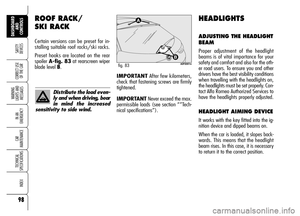
Preset hooks are located on the rear
spoiler A-fig. 83at rearscreen wiper
blade level B.
A0F0097mfig. 83
HEADLIGHTS
ADJUSTING THE HEADLIGHT
BEAM
Proper adjustment of the headlight
beams is of vital importance for your
safety and comfort and also for the oth-
er road users. To ensure you and other
drivers have the best visibility conditions
when travelling with the headlights on,
the headlights must be set properly. Con-
tact Alfa Romeo Authorized Services to
have the headlights properly adjusted.
HEADLIGHT AIMING DEVICE
It works with the key fitted into the ig-
nition device and dipped beams on.
When the car is loaded, it slopes back-
wards. This means that the headlight
beam rises. In this case, it is necessary
to return it to the correct position.
Distribute the load even-
ly and when driving, bear
in mind the increased
sensitivity to side wind.
IMPORTANTAfter few kilometers,
check that fastening screws are firmly
tightened.
IMPORTANTNever exceed the max.
permissible loads (see section “”Tech-
nical specifications”).
Page 109 of 267
107
SAFETY
DEVICES
WARNING
LIGHTS AND
MESSAGES
IN AN
EMERGENCY
CAR
MAINTENANCE
TECHNICAL
SPECIFICATIONS
INDEX
DASHBOARD
AND
CONTROLS
CORRECT USE
OF THE CAR
RADIO TRANSMITTERS AND
MOBILE PHONES
Radio transceiver equipment (e.g.: e-
tacs mobile phones, HAM radio systems
and the like) shall not be used inside the
car unless a separate aerial is mounted
on the roof.
The use of similar devices inside the pas-
senger compartment (without separat-
ed aerial) produces radio-frequency elec-
tromagnetic fields which, amplified by
the resonance effects inside the pas-
senger compartment, may cause elec-
trical systems equipping the car to mal-
function. This could compromise safety
in addition to constituting a potential
hazard for the passengers.
In addition, transmission and reception
of these devices may be affected by the
shielding effect of the car body.
As concerns EC-approved mobile phones
(GSM, GPRS, UMTS), strictly comply
with the instructions for use provided by
the mobile phone’s manufacturer.
ACCESSORIES
PURCHASED
BY THE OWNER
If after buying the car, you decide to in-
stall electrical accessories that require a
permanent electric supply (alarm, satel-
lite antitheft system, etc.) or accessories
that in any case burden the electric sup-
ply, contact Alfa Romeo Authorized Ser-
vices, whose qualified personnel, besides
suggesting the most suitable devices be-
longing to Lineaccessori Alfa Romeo, will
also evaluate the overall electric absorp-
tion, checking whether the car’s electric
system is able to withstand the load re-
quired, or whether it needs to be inte-
grated with a more powerful battery.
Take care when fitting
additional spoilers, al-
loy rims and non-standard
wheel caps: they might reduce
ventilation of the brakes, thus
their efficiency, during abrupt
and repeated braking, or long
downhill slopes. Make sure
that nothing (mats, etc.) gets
in the way of the pedals when
they are pushed down.
WARNING