stop start ALFA ROMEO GIULIA 2021 User Guide
[x] Cancel search | Manufacturer: ALFA ROMEO, Model Year: 2021, Model line: GIULIA, Model: ALFA ROMEO GIULIA 2021Pages: 284, PDF Size: 8.87 MB
Page 57 of 284
55
the number of buttons and knobs indicate that
the selected feature is on/off. If no operation
is performed for a predetermined time, the
pop-up will close on the display.
Humidity Sensor
The Humidity Sensor helps prevent the
windows from fogging up. The AUTO function
(indicator illuminated) must be on for the
Humidity Sensor to function.
When outside temperature is low, the system
may turn the compressor on and turn air recir-
culation off for safer driving.
Stop/Start
The Stop/Start system shuts off the engine
when the vehicle speed is 0 mph (0 km/h), as
a fuel conservation measure.
In order to maintain comfort in the cabin, the
Stop/Start feature will not activate if any of the
following conditions exist:
The climate control system is in AUTO mode
(indicator illuminated), and the vehicle has
yet to reach the set temperature
The climate control system is in LO maximum
cooling
The climate control system is in HI maximum
heating
The climate control system is in the MAX-DEF
status
When the Stop/Start system is active, the
engine will restart if the inside temperature
changes significantly, or if the LO setting, or
MAX-DEF setting, is activated.
With Stop/Start system on (engine is off), air
flow is reduced to keep the compartment
comfort conditions for longer.
Until the temperature drastically changes within
the cabin, the climate control system will
continue to maintain the temperature while the
engine is off. By deactivating the Stop/Start
system with the button (located by the head
-
light switch), the climate control system operates
normally according to the settings.
NOTE:
In harsh climate conditions, limit the use of
the Stop/Start system to prevent the
compressor from continuously switching on
and off. This will prevent rapid misting of the
windows and the accumulation of humidity
in the passenger compartment.
When the Stop/Start system is on, the
climate control system will always take air in
from outside, reducing the probability of the
windows fogging up.
System Maintenance
In winter months, the Climate Control system
must be turned on at least once a month for
approximately ten minutes.
Have the system inspected at an authorized
dealer before the summer.
INTERIOR STORAGE AND
EQUIPMENT
Glove Compartment
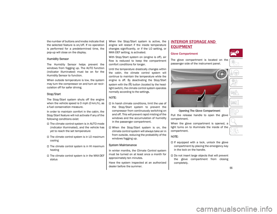
The glove compartment is located on the
passenger side of the instrument panel.
Opening The Glove Compartment
Pull the release handle to open the glove
compartment.
When the glove compartment is opened, a
light turns on to illuminate the inside of the
compartment.
NOTE:
If equipped with a lock, unlock the glove
compartment by placing the emergency key
in the lock on the handle.
Do not insert large objects that will prevent
the glove compartment from closing
completely.
21_GA_OM_EN_USC_t.book Page 55
Page 60 of 284
GETTING TO KNOW YOUR VEHICLE
58
NOTE:
Do not place the key fob or any other type of
metal/magnetized object inside the mobile
phone housing or near the wireless
charging pad.
Be sure to place the mobile device correctly
(display facing upward) on the wireless
charging pad.
The ignition must be in the ON/RUN position
in order for the phone to charge.
To avoid interference with the key fob
search, the wireless charging pad will stop
charging when any door is opened.The following messages will display in the
radio system:
“Your Phone Is Being Charged” — The phone
has begun to charge.
“Phone Fully Charged” — The phone has
completed charging its battery.
“Foreign Object Detected” — The phone is
not enabled for wireless charging or an
object that is not permitted has been placed
on the wireless charging pad.
“Unavailable System” — There is a malfunc
-
tion with the wireless charging pad.
The driver can deactivate these messages
through the radio system. Refer to the Infor -
mation and Entertainment System Owner’s
Manual Supplement for further information.
POWER WINDOWS
Power Window Controls
The power window switches work with the igni -
tion in the ACC or ON/RUN position and for
three minutes after the ignition has been
placed in the OFF position. When one of the
front doors is opened, this operation is
disabled.
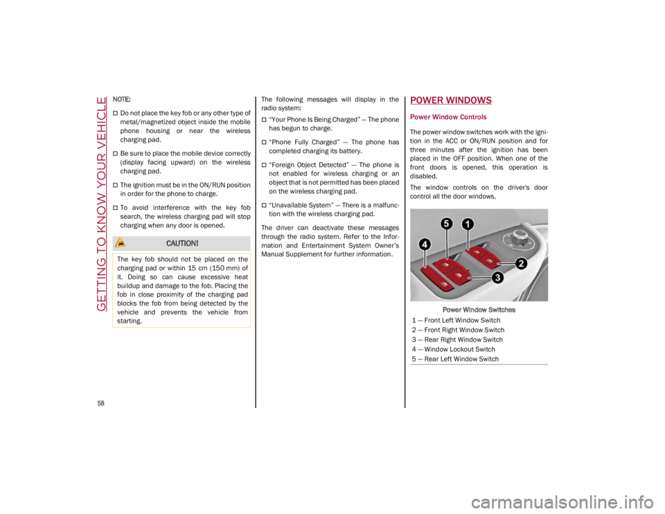
The window controls on the driver's door
control all the door windows.
Power Window Switches
CAUTION!
The key fob should not be placed on the
charging pad or within 15 cm (150 mm) of
it. Doing so can cause excessive heat
buildup and damage to the fob. Placing the
fob in close proximity of the charging pad
blocks the fob from being detected by the
vehicle and prevents the vehicle from
starting.
1 — Front Left Window Switch
2 — Front Right Window Switch
3 — Rear Right Window Switch
4 — Window Lockout Switch
5 — Rear Left Window Switch
21_GA_OM_EN_USC_t.book Page 58
Page 63 of 284
61
Venting Sunroof
To bring the roof into vent position, push and
release the vent button.
This type of vent opening can be activated
regardless of the position of the sunroof.
When starting with the roof in the closed posi-
tion, pushing the vent button automatically
causes the sunroof to open to the vent posi -
tion. If the roof is already open, the button
must be held until the roof reaches the
vent-opening position.
Pushing vent button again during automatic
movement of the roof will stop it.
Sun Shade Operation
The front sunshade is power operated.
Push the Power Shade open/close button
toward the rear of the vehicle to open the front
sun shade to the three quarter open position.
Pushing the button a second time will open the
sunshade completely.
Push the Power Shade open/close button
toward the front of the vehicle to close the sun
shade.
The automatic motion can be interrupted in
any position by pushing the Power Shade
open/close button again.
To open the rear sunshade, pull sunshade
manually toward the rear of the vehicle.
Pinch Protect Feature
The sunroof has an anti-pinch safety system
capable of detecting the presence of an
obstacle during the closing movement. If an
obstacle is detected, the system intervenes
and the movement of the sunroof is immedi -
ately reversed into opening.
Re-Initialization Procedure
Automatic operation of the sunroof must be
re-initialized in case of faulty sunroof opera -
tion. It may also be necessary to initialize the
sunroof after the vehicle’s battery has been
disconnected and then reconnected.
NOTE:
The anti-pinch safety device is deactivated
during the re-initialization procedure.
Proceed as follows:
1. With the ignition in the ON/RUN position, make sure the sunroof glass is fully closed
(sunshade open).
2. Open the driver’s side door, and place the ignition in the OFF position.
3. Within five seconds, place the ignition in the ACC or ON/RUN position.
4. Within 10 seconds, push and hold the sunroof close switch (forward). After 8 - 10
seconds of holding the switch, the
re-initialization process will begin. Continue to hold the switch while the
sunroof motor cycles, and the sunshade
will fully close.
5. Once the sunroof glass and the power sunshade have stopped motion, release
the sunroof close switch, then push and
hold it again within five seconds. Continue
to hold the switch while the sunshade fully
opens, the sunroof glass fully opens,
followed by the glass fully closing then the
sunshade fully closing.
6. Release the switch once the operations stop. Re-initialization of the sunroof
motors is now complete.
NOTE:
If the switch is released prior to full completion
of the operations described, the entire
re-initialization procedure must be repeated
from step 1.
7. Confirm express operations for the sunroof glass and sunshade are functional
for opening and closing operations.
Sunroof Maintenance
Use only a non-abrasive cleaner and a soft
cloth to clean the glass panel. Periodically
check for and clear out any debris that may
have collected in the tracks.
21_GA_OM_EN_USC_t.book Page 61
Page 75 of 284
73
Show Audio Info: allows you to activate/
deactivate repetition of the audio function
screens (Radio and Media) also on the
instrument panel display.
Show Nav Info: allows you to activate/deac-
tivate repetition of the navigator function
screens also on the instrument panel
display.
Digital speed on all screens: this allows you
to activate/deactivating of digital speed on
the instrument panel display screens other
than the main screen.
Consumption Bar: allows you to activate/
deactivate the consumption baron the
display screens of the instrument panel
where it is available.
Performance pages: allows you to choose,
for each driving mode, one of the two alter -
native contents displayed in the screen.
Custom areas: allows you to select which
content to display in each of the three
customizable areas on the display of the
instrument panel: time, date, outside
temperature, radio information, compass.
Restore Cluster Settings: deletes the
current settings and restores the factory
settings.
To access and change the setting, turn and
push the Rotary Pad or press the desired
setting on the touchscreen.
WARNING LIGHTS AND
MESSAGES ON THE
INSTRUMENT PANEL
The following pages consist of warning lights
and messages.
NOTE:
The warning light turns on together with a
dedicated message and/or chime when
applicable. These indications are precau -
tionary and as such must not be considered
as exhaustive and/or alternative to the
information contained in the Owner’s
Manual, which you are advised to read care -
fully in all cases. Always refer to the informa -
tion in this section in the event of a failure
indication.
The failure indicators appearing on the
display are divided into two categories: very
serious and less serious faults. Serious
faults are indicated by a repeated and
prolonged warning "cycle.” Less serious
faults are indicated by a warning "cycle" with
a shorter duration. You can stop the
warning cycle in both cases by pushing the
button located on the windshield wiper
stalk. The instrument panel warning light
will stay on until the cause of the failure is
eliminated.
Red Warning Lights
Air Bag Warning Light
This warning light will illuminate to
indicate a fault with the air bag, and
will turn on for four to eight seconds
as a bulb check when the ignition is
placed in the ON/RUN or ACC/ON/RUN posi -
tion. This light will illuminate with a single
chime when a fault with the air bag has been
detected, it will stay on until the fault is
cleared. If the light is either not on during
startup, stays on, or turns on while driving,
have the system inspected at an authorized
dealer as soon as possible.
Brake Warning Light
This warning light monitors various
brake functions, including brake
fluid level and parking brake applica -
tion. If the brake light turns on it may
indicate that the parking brake is applied, that
the brake fluid level is low, or that there is a
problem with the Anti-Lock Brake System
reservoir.
If the light remains on when the parking brake
has been disengaged, and the fluid level is at
the full mark on the master cylinder reservoir,
it indicates a possible brake hydraulic system
malfunction or that a problem with the Brake
Booster has been detected by the Anti-Lock
Brake System (ABS) / Electronic Stability
Control (ESC) system. In this case, the light will
remain on until the condition has been
21_GA_OM_EN_USC_t.book Page 73
Page 78 of 284
GETTING TO KNOW YOUR INSTRUMENT PANEL
76
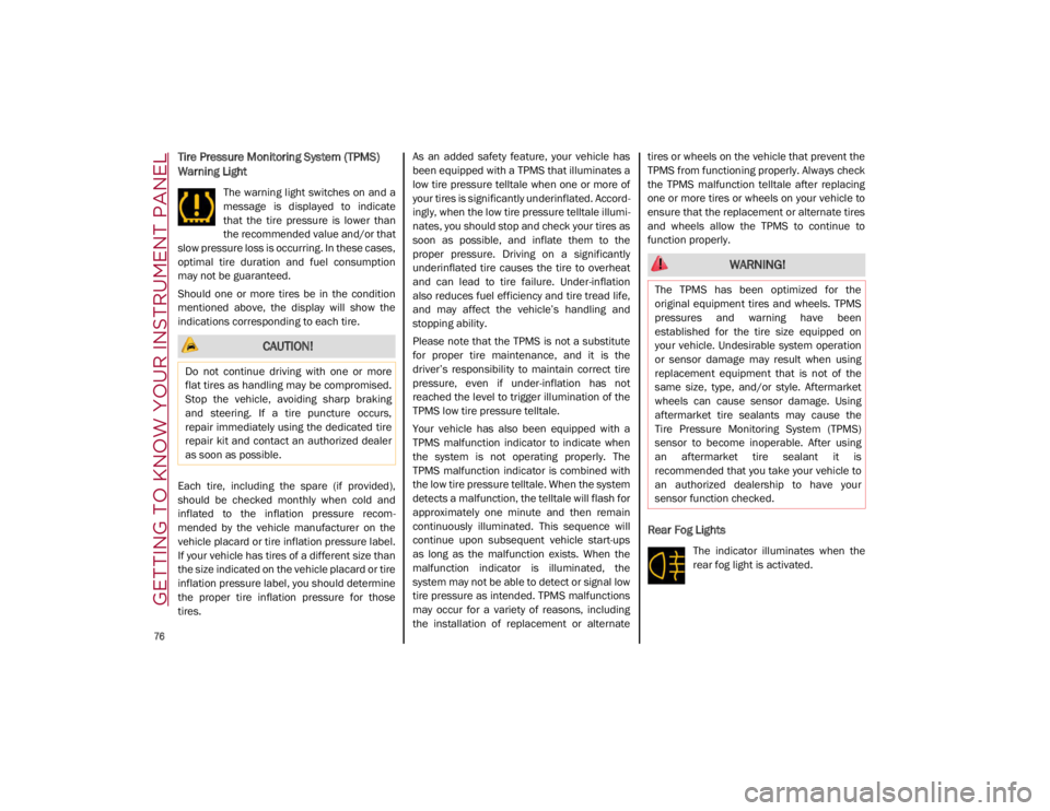
Tire Pressure Monitoring System (TPMS)
Warning Light
The warning light switches on and a
message is displayed to indicate
that the tire pressure is lower than
the recommended value and/or that
slow pressure loss is occurring. In these cases,
optimal tire duration and fuel consumption
may not be guaranteed.
Should one or more tires be in the condition
mentioned above, the display will show the
indications corresponding to each tire.
Each tire, including the spare (if provided),
should be checked monthly when cold and
inflated to the inflation pressure recom -
mended by the vehicle manufacturer on the
vehicle placard or tire inflation pressure label.
If your vehicle has tires of a different size than
the size indicated on the vehicle placard or tire
inflation pressure label, you should determine
the proper tire inflation pressure for those
tires. As an added safety feature, your vehicle has
been equipped with a TPMS that illuminates a
low tire pressure telltale when one or more of
your tires is significantly underinflated. Accord
-
ingly, when the low tire pressure telltale illumi -
nates, you should stop and check your tires as
soon as possible, and inflate them to the
proper pressure. Driving on a significantly
underinflated tire causes the tire to overheat
and can lead to tire failure. Under-inflation
also reduces fuel efficiency and tire tread life,
and may affect the vehicle’s handling and
stopping ability.
Please note that the TPMS is not a substitute
for proper tire maintenance, and it is the
driver’s responsibility to maintain correct tire
pressure, even if under-inflation has not
reached the level to trigger illumination of the
TPMS low tire pressure telltale.
Your vehicle has also been equipped with a
TPMS malfunction indicator to indicate when
the system is not operating properly. The
TPMS malfunction indicator is combined with
the low tire pressure telltale. When the system
detects a malfunction, the telltale will flash for
approximately one minute and then remain
continuously illuminated. This sequence will
continue upon subsequent vehicle start-ups
as long as the malfunction exists. When the
malfunction indicator is illuminated, the
system may not be able to detect or signal low
tire pressure as intended. TPMS malfunctions
may occur for a variety of reasons, including
the installation of replacement or alternate tires or wheels on the vehicle that prevent the
TPMS from functioning properly. Always check
the TPMS malfunction telltale after replacing
one or more tires or wheels on your vehicle to
ensure that the replacement or alternate tires
and wheels allow the TPMS to continue to
function properly.
Rear Fog Lights
The indicator illuminates when the
rear fog light is activated.
CAUTION!
Do not continue driving with one or more
flat tires as handling may be compromised.
Stop the vehicle, avoiding sharp braking
and steering. If a tire puncture occurs,
repair immediately using the dedicated tire
repair kit and contact an authorized dealer
as soon as possible.
WARNING!
The TPMS has been optimized for the
original equipment tires and wheels. TPMS
pressures and warning have been
established for the tire size equipped on
your vehicle. Undesirable system operation
or sensor damage may result when using
replacement equipment that is not of the
same size, type, and/or style. Aftermarket
wheels can cause sensor damage. Using
aftermarket tire sealants may cause the
Tire Pressure Monitoring System (TPMS)
sensor to become inoperable. After using
an aftermarket tire sealant it is
recommended that you take your vehicle to
an authorized dealership to have your
sensor function checked.
21_GA_OM_EN_USC_t.book Page 76
Page 81 of 284
79
Also check visually for any fluid leaks. Contact
an authorized dealer if the telltale comes on
when the engine is started again.
If the vehicle is used under demanding condi-
tions (e.g. in high-performance driving): slow
down and, if the warning light stays on, stop
the vehicle. Stop for two or three minutes with
the engine running and slightly accelerated to
facilitate better coolant circulation, then turn
the engine off. Check that the coolant level is
correct as described above.
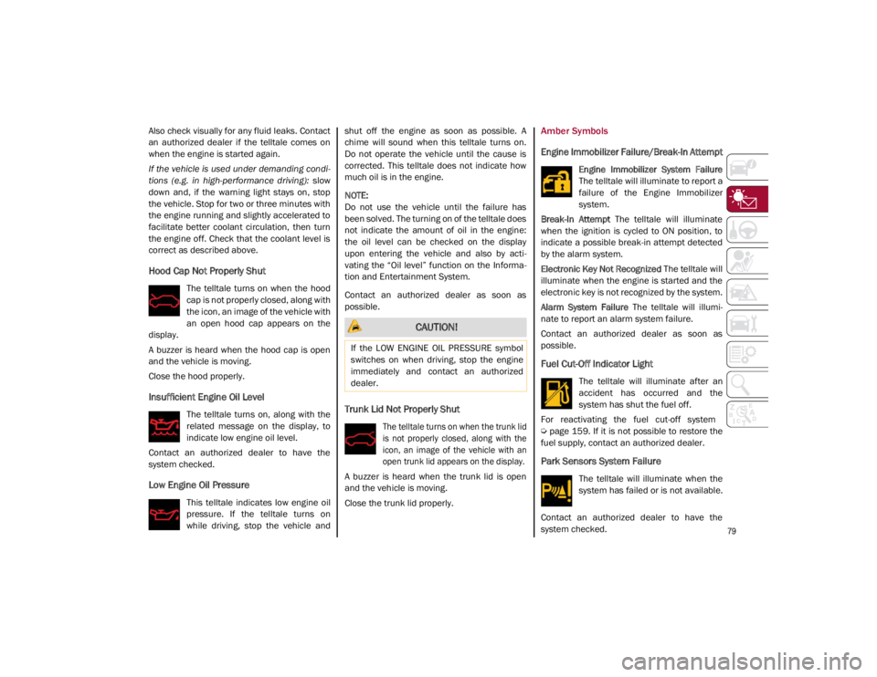
Hood Cap Not Properly Shut
The telltale turns on when the hood
cap is not properly closed, along with
the icon, an image of the vehicle with
an open hood cap appears on the
display.
A buzzer is heard when the hood cap is open
and the vehicle is moving.
Close the hood properly.
Insufficient Engine Oil Level
The telltale turns on, along with the
related message on the display, to
indicate low engine oil level.
Contact an authorized dealer to have the
system checked.
Low Engine Oil Pressure
This telltale indicates low engine oil
pressure. If the telltale turns on
while driving, stop the vehicle and shut off the engine as soon as possible. A
chime will sound when this telltale turns on.
Do not operate the vehicle until the cause is
corrected. This telltale does not indicate how
much oil is in the engine.
NOTE:
Do not use the vehicle until the failure has
been solved. The turning on of the telltale does
not indicate the amount of oil in the engine:
the oil level can be checked on the display
upon entering the vehicle and also by acti
-
vating the “Oil level” function on the Informa -
tion and Entertainment System.
Contact an authorized dealer as soon as
possible.
Trunk Lid Not Properly Shut
The telltale turns on when the trunk lid
is not properly closed, along with the
icon, an image of the vehicle with an
open trunk lid appears on the display.
A buzzer is heard when the trunk lid is open
and the vehicle is moving.
Close the trunk lid properly.
Amber Symbols
Engine Immobilizer Failure/Break-In Attempt
Engine Immobilizer System Failure
The telltale will illuminate to report a
failure of the Engine Immobilizer
system.
Break-In Attempt The telltale will illuminate
when the ignition is cycled to ON position, to
indicate a possible break-in attempt detected
by the alarm system.
Electronic Key Not Recognized The telltale will
illuminate when the engine is started and the
electronic key is not recognized by the system.
Alarm System Failure The telltale will illumi -
nate to report an alarm system failure.
Contact an authorized dealer as soon as
possible.
Fuel Cut-Off Indicator Light
The telltale will illuminate after an
accident has occurred and the
system has shut the fuel off.
For reactivating the fuel cut-off system
Ú
page 159. If it is not possible to restore the
fuel supply, contact an authorized dealer.
Park Sensors System Failure
The telltale will illuminate when the
system has failed or is not available.
Contact an authorized dealer to have the
system checked.
CAUTION!
If the LOW ENGINE OIL PRESSURE symbol
switches on when driving, stop the engine
immediately and contact an authorized
dealer.
21_GA_OM_EN_USC_t.book Page 79
Page 82 of 284
GETTING TO KNOW YOUR INSTRUMENT PANEL
80
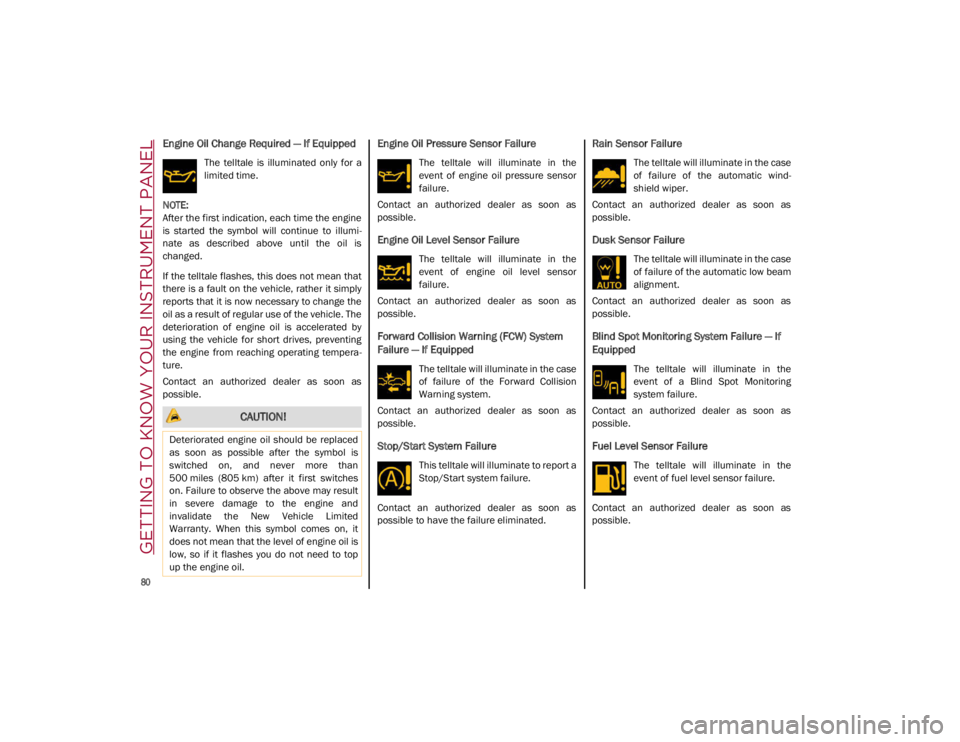
Engine Oil Change Required — If Equipped
The telltale is illuminated only for a
limited time.
NOTE:
After the first indication, each time the engine
is started the symbol will continue to illumi -
nate as described above until the oil is
changed.
If the telltale flashes, this does not mean that
there is a fault on the vehicle, rather it simply
reports that it is now necessary to change the
oil as a result of regular use of the vehicle. The
deterioration of engine oil is accelerated by
using the vehicle for short drives, preventing
the engine from reaching operating tempera -
ture.
Contact an authorized dealer as soon as
possible.
Engine Oil Pressure Sensor Failure
The telltale will illuminate in the
event of engine oil pressure sensor
failure.
Contact an authorized dealer as soon as
possible.
Engine Oil Level Sensor Failure
The telltale will illuminate in the
event of engine oil level sensor
failure.
Contact an authorized dealer as soon as
possible.
Forward Collision Warning (FCW) System
Failure — If Equipped
The telltale will illuminate in the case
of failure of the Forward Collision
Warning system.
Contact an authorized dealer as soon as
possible.
Stop/Start System Failure
This telltale will illuminate to report a
Stop/Start system failure.
Contact an authorized dealer as soon as
possible to have the failure eliminated.
Rain Sensor Failure
The telltale will illuminate in the case
of failure of the automatic wind -
shield wiper.
Contact an authorized dealer as soon as
possible.
Dusk Sensor Failure
The telltale will illuminate in the case
of failure of the automatic low beam
alignment.
Contact an authorized dealer as soon as
possible.
Blind Spot Monitoring System Failure — If
Equipped
The telltale will illuminate in the
event of a Blind Spot Monitoring
system failure.
Contact an authorized dealer as soon as
possible.
Fuel Level Sensor Failure
The telltale will illuminate in the
event of fuel level sensor failure.
Contact an authorized dealer as soon as
possible.
CAUTION!
Deteriorated engine oil should be replaced
as soon as possible after the symbol is
switched on, and never more than
500 miles (805 km) after it first switches
on. Failure to observe the above may result
in severe damage to the engine and
invalidate the New Vehicle Limited
Warranty. When this symbol comes on, it
does not mean that the level of engine oil is
low, so if it flashes you do not need to top
up the engine oil.
21_GA_OM_EN_USC_t.book Page 80
Page 85 of 284
83
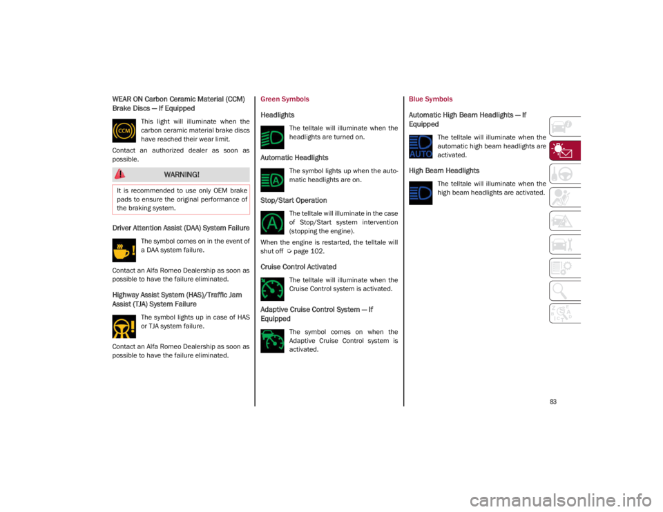
WEAR ON Carbon Ceramic Material (CCM)
Brake Discs — If Equipped
This light will illuminate when the
carbon ceramic material brake discs
have reached their wear limit.
Contact an authorized dealer as soon as
possible.
Driver Attention Assist (DAA) System Failure
The symbol comes on in the event of
a DAA system failure.
Contact an Alfa Romeo Dealership as soon as
possible to have the failure eliminated.
Highway Assist System (HAS)/Traffic Jam
Assist (TJA) System Failure
The symbol lights up in case of HAS
or TJA system failure.
Contact an Alfa Romeo Dealership as soon as
possible to have the failure eliminated.
Green Symbols
Headlights
The telltale will illuminate when the
headlights are turned on.
Automatic Headlights
The symbol lights up when the auto -
matic headlights are on.
Stop/Start Operation
The telltale will illuminate in the case
of Stop/Start system intervention
(stopping the engine).
When the engine is restarted, the telltale will
shut off
Ú
page 102.
Cruise Control Activated
The telltale will illuminate when the
Cruise Control system is activated.
Adaptive Cruise Control System — If
Equipped
The symbol comes on when the
Adaptive Cruise Control system is
activated.
Blue Symbols
Automatic High Beam Headlights — If
Equipped
The telltale will illuminate when the
automatic high beam headlights are
activated.
High Beam Headlights
The telltale will illuminate when the
high beam headlights are activated.
WARNING!
It is recommended to use only OEM brake
pads to ensure the original performance of
the braking system.
21_GA_OM_EN_USC_t.book Page 83
Page 90 of 284
STARTING AND OPERATING
88
If Engine Fails To Start
Starting the Engine with Key Fob Battery Run
Down or Drained
If the ignition does not respond when the
button is pushed, the key fob battery might be
run down or drained. Therefore, the system
does not detect the presence of the key fob in
the vehicle, and will display a dedicated
message.
For more information on starting with a
discharged key fob battery
Ú
page 19.
After Starting — Warming Up The Engine
Proceed as follows:
Travel slowly, letting the engine run at a
reduced RPM, without accelerating suddenly.
It is recommended to wait until the digital
engine coolant temperature indicator starts
to rise for maximum performance.
Stopping The Engine
To stop the engine, proceed as follows:
1. Park the vehicle in a position that is not
dangerous for oncoming traffic.
2. Engage the PARK (P) mode.
3. With engine idling, push the ENGINE START/STOP button on the steering wheel
to STOP the engine.
NOTE:
Do not leave the ignition in ACC mode when
the engine is off.
To shut off the engine with vehicle speed
greater than 5 mph (8 km/h), you must push
and hold the ignition or push the ENGINE
START/STOP button three times consecutively within a few seconds. The engine will shut
down, and the ignition will be placed in the
ACC mode
With the keyless ignition system, it is possible
to leave the vehicle taking the key fob with you
without the engine switching off. The vehicle
will inform the absence of the key on board,
only if the doors are closed.
Stopping the engine (cycling from the ACC to
the OFF position), the accessories are still
powered for about three minutes, or until a
door is opened.
When the ignition is in the OFF mode, the
window switches remain active for three
minutes. Opening a front door will cancel this
function.
After severe driving, idle the engine to allow
the temperature inside the engine compart
-
ment to cool before shutting off the engine.
Turbocharger Cool Down
It is recommended before switching the
vehicle off, to keep the engine idling for a few
minutes so that the turbocharger can be suit -
ably lubricated. This procedure is particularly
recommended after severe driving.
After a full load operation, keep the engine idling
for three to five minutes before switching it off.
This time allows the lubricating oil and the
engine coolant to eliminate the excessive heat
from combustion chamber, bearings, inner
components and turbocharger.
WARNING!
Never pour fuel or other flammable liquid
into the throttle body air inlet opening in
an attempt to start the vehicle. This could
result in flash fire causing serious
personal injury.
Do not attempt to push or tow your vehicle
to get it started. Vehicles equipped with an
automatic transmission cannot be started
this way. Unburned fuel could enter the
catalytic converter and once the engine
has started, ignite and damage the
converter and vehicle.
If the vehicle has a discharged battery,
booster cables may be used to obtain a start
from a booster battery or the battery in
another vehicle
Ú
page 199. This type of
start can be dangerous if done improperly.
CAUTION!
To prevent damage to the starter, do not
continuously crank the engine for more than
25 seconds at a time. Wait 60 seconds before
trying again.
21_GA_OM_EN_USC_t.book Page 88
Page 92 of 284
STARTING AND OPERATING
90
100 to 300 miles (160 to 483 km):
Press the accelerator pedal slowly and not
more than halfway to avoid rapid accelera-
tion in lower gears (FIRST to THIRD gears).
Avoid aggressive braking.
Drive with the engine speed less than
5,000 RPM.
Maintain vehicle speed below 70 mph
(112 km/h) and observe local speed limits.
300 to 500 miles (483 to 805 km):
Exercise the full engine RPM range, shifting
manually (paddles or gear shift) at higher
RPM when possible.
Do not perform sustained operation with
the accelerator pedal at wide open throttle.
Maintain vehicle speed below 85 mph
(136 km/h) and observe local speed limits.
For the first 1,500 miles (2,414 km):
Do not participate in track events, sport
driving schools, or similar activities during
the first 1,500 miles (2,414 km).
NOTE:
Monitor engine oil with every refueling and add
if necessary. Oil and fuel consumption may be
higher through the first oil change interval.
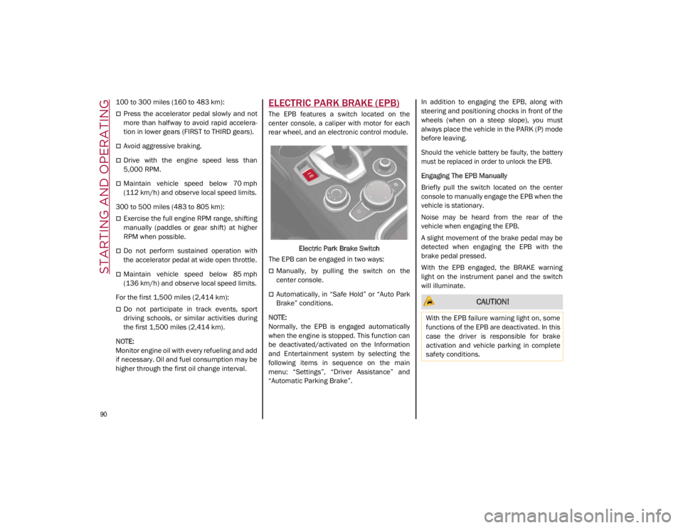
ELECTRIC PARK BRAKE (EPB)
The EPB features a switch located on the
center console, a caliper with motor for each
rear wheel, and an electronic control module.
Electric Park Brake Switch
The EPB can be engaged in two ways:
Manually, by pulling the switch on the
center console.
Automatically, in “Safe Hold” or “Auto Park
Brake” conditions.
NOTE:
Normally, the EPB is engaged automatically
when the engine is stopped. This function can
be deactivated/activated on the Information
and Entertainment system by selecting the
following items in sequence on the main
menu: “Settings”, “Driver Assistance” and
“Automatic Parking Brake”. In addition to engaging the EPB, along with
steering and positioning chocks in front of the
wheels (when on a steep slope), you must
always place the vehicle in the PARK (P) mode
before leaving.
Should the vehicle battery be faulty, the battery
must be replaced in order to unlock the EPB.
Engaging The EPB Manually
Briefly pull the switch located on the center
console to manually engage the EPB when the
vehicle is stationary.
Noise may be heard from the rear of the
vehicle when engaging the EPB.
A slight movement of the brake pedal may be
detected when engaging the EPB with the
brake pedal pressed.
With the EPB engaged, the BRAKE warning
light on the instrument panel and the switch
will illuminate. CAUTION!
With the EPB failure warning light on, some
functions of the EPB are deactivated. In this
case the driver is responsible for brake
activation and vehicle parking in complete
safety conditions.
21_GA_OM_EN_USC_t.book Page 90