boot Alfa Romeo Giulietta 2012 Owner handbook (in English)
[x] Cancel search | Manufacturer: ALFA ROMEO, Model Year: 2012, Model line: Giulietta, Model: Alfa Romeo Giulietta 2012Pages: 297, PDF Size: 9.37 MB
Page 171 of 297
167
GETTING
TO KNOW
YOUR CAR
SAFETY
STARTING
AND DRIVING
IN AN
EMERGENCY
SERVICING AND
MAINTENANCE
TECHNICAL
SPECIFICATIONS
CONTENTS
When you have finished:
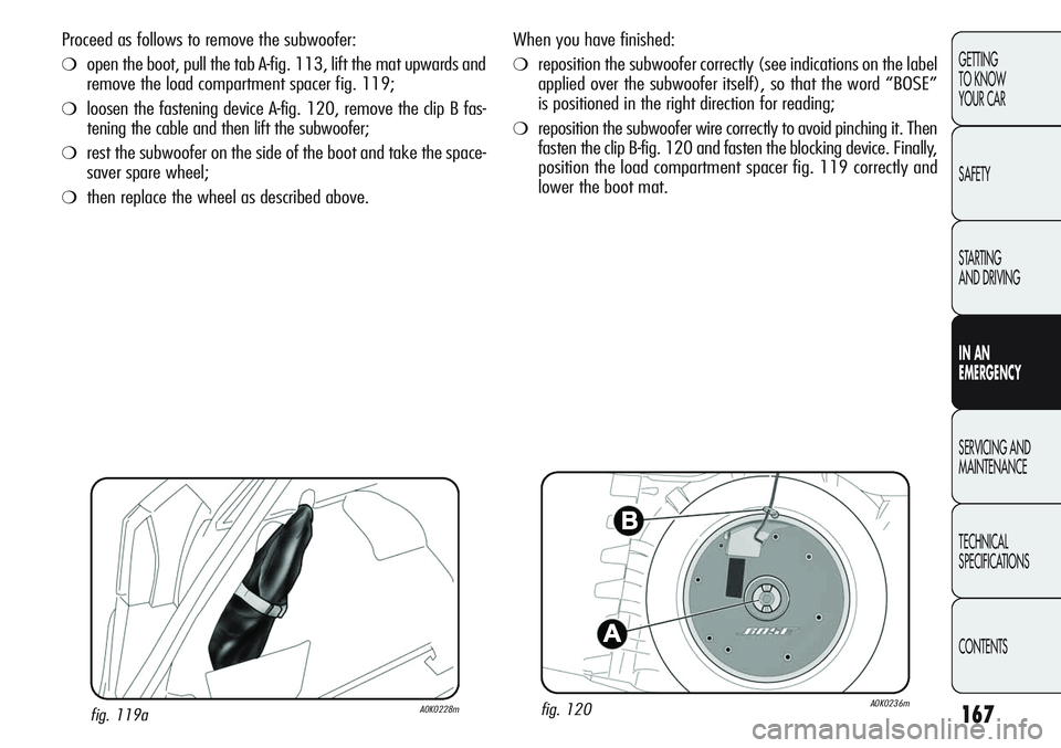
❍reposition the subwoofer correctly (see indications on the label
applied over the subwoofer itself), so that the word “BOSE”
is positioned in the right direction for reading;
❍reposition the subwoofer wire correctly to avoid pinching it. Then
fasten the clip B-fig. 120 and fasten the blocking device. Finally,
position the load compartment spacer fig. 119 correctly and
lower the boot mat.
fig. 120A0K0236mfig. 119aA0K0228m
Proceed as follows to remove the subwoofer:
❍open the boot, pull the tab A-fig. 113, lift the mat upwards and
remove the load compartment spacer fig. 119;
❍loosen the fastening device A-fig. 120, remove the clip B fas-
tening the cable and then lift the subwoofer;
❍rest the subwoofer on the side of the boot and take the space-
saver spare wheel;
❍then replace the wheel as described above.
Page 172 of 297
168
GETTING
TO KNOW
YOUR CAR
SAFETY
STARTING
AND DRIVING
IN AN
EMERGENCY
SERVICING AND
MAINTENANCE
TECHNICAL
SPECIFICATIONS
CONTENTS
REFITTING THE WHEEL
Following the procedure previously described, raise the car and
remove the space-saver spare wheel.
Proceed as follows:
❍make sure the contact surfaces between standard wheel and
hub are clean so that the fastening bolts will not come loose;
❍for versions with steel rims: fixed the wheel hub onto the rim;
❍fit the hub cap by aligning the crescent hole with the bolt you
have fitted, then insert the other 4 bolts;
❍tighten the retaining bolts using wrench A-fig. 115;
❍lower the car and remove the jack;
❍use wrench A-fig. 115 to fully tighten the bolts, following the
sequence shown in fig. 118;
When you have finished:
❍stow the space-saver spare wheel in the compartment provid-
ed in the boot;
❍insert the jack and the other tools in the container;
❍arrange the container and tools on the space-saver spare wheel;
❍reposition the boot mat correctly.
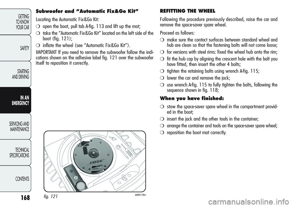
Subwoofer and “Automatic Fix&Go Kit”
Locating the Automatic Fix&Go Kit:
❍open the boot, pull tab A-fig. 113 and lift up the mat;
❍take the “Automatic Fix&Go Kit” located on the left side of the
boot (fig. 121);
❍inflate the wheel (see “Automatic Fix&Go Kit”).
IMPORTANT If you need to remove the subwoofer follow the indi-
cations shown on the adhesive label fig. 121 over the subwoofer
itself to reposition it correctly.
fig. 121A0K0178m
Page 173 of 297
169
GETTING
TO KNOW
YOUR CAR
SAFETY
STARTING
AND DRIVING
IN AN
EMERGENCY
SERVICING AND
MAINTENANCE
TECHNICAL
SPECIFICATIONS
CONTENTS
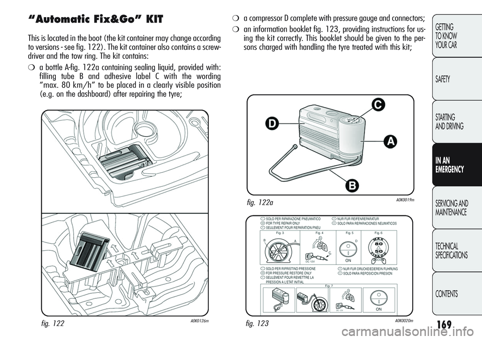
“Automatic Fix&Go” KIT
This is located in the boot (the kit container may change according
to versions - see fig. 122). The kit container also contains a screw-
driver and the tow ring. The kit contains:
❍a bottle A-fig. 122a containing sealing liquid, provided with:
filling tube B and adhesive label C with the wording
“max. 80 km/h” to be placed in a clearly visible position
(e.g. on the dashboard) after repairing the tyre;
fig. 122aA0K0019m
fig. 122A0K0126mfig. 123A0K0020m
❍a compressor D complete with pressure gauge and connectors;
❍an information booklet fig. 123, providing instructions for us-
ing the kit correctly. This booklet should be given to the per-
sons charged with handling the tyre treated with this kit;
Page 180 of 297
–
–
55W
55W
D1S
24W
10W
–
–
–
5W
55W
21W
21W
10W
5W
5W
5WLED
LED
H7
H1
F
PY24W
R10W
LED
LED
LED
W5W
H3
H21W
P21W
C10W
W5W
C5W
W5W
176
GETTING
TO KNOW
YOUR CAR
SAFETY
STARTING
AND DRIVING
IN AN
EMERGENCY
SERVICING AND
MAINTENANCE
TECHNICAL
SPECIFICATIONS
CONTENTS
–
–
D
E
–
B
B
–
–
–
A
E
B
B
C
A
C
A
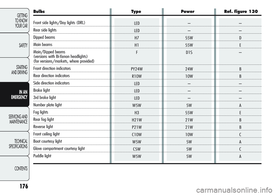
Bulbs Type Power Ref. figure 130
Front side lights/Day lights (DRL)
Rear side lights
Dipped beams
Main beams
Main/Dipped beams
(versions with Bi-Xenon headlights)
(for versions/markets, where provided)
Front direction indicators
Rear direction indicators
Side direction indicators
Brake light
3rd brake light
Number plate light
Fog lights
Rear fog light
Reverse light
Front ceiling light
Boot courtesy light
Glove compartment courtesy light
Puddle light
Page 183 of 297
179
GETTING
TO KNOW
YOUR CAR
SAFETY
STARTING
AND DRIVING
IN AN
EMERGENCY
SERVICING AND
MAINTENANCE
TECHNICAL
SPECIFICATIONS
CONTENTS
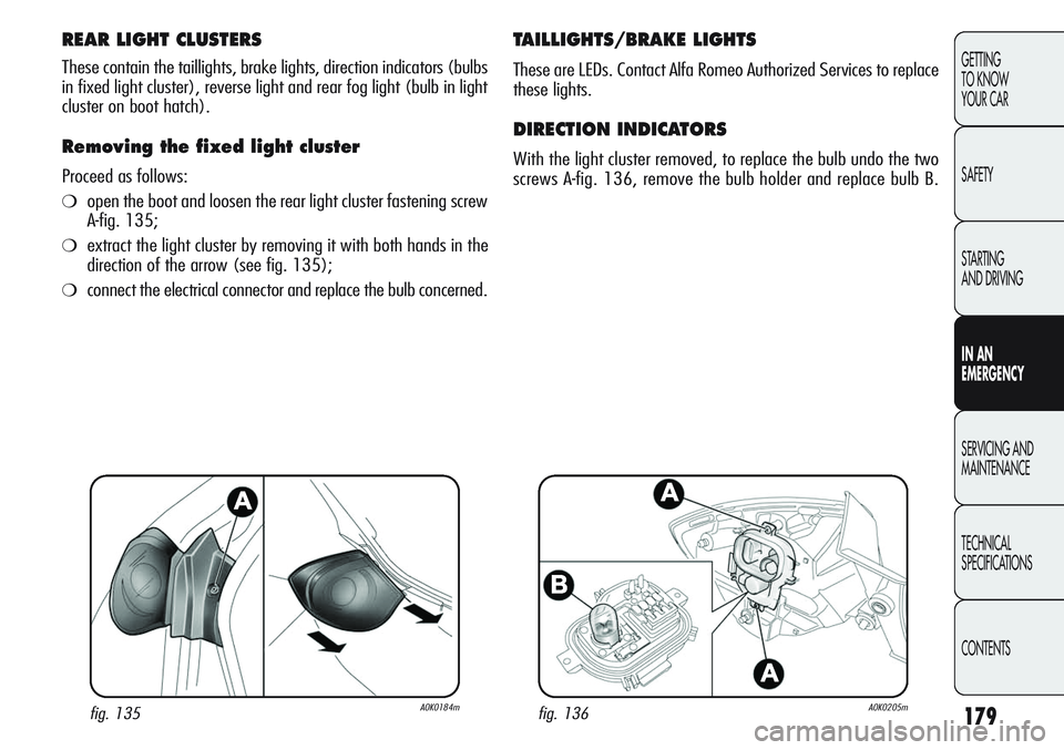
REAR LIGHT CLUSTERS
These contain the taillights, brake lights, direction indicators (bulbs
in fixed light cluster), reverse light and rear fog light (bulb in light
cluster on boot hatch).
Removing the fixed light cluster
Proceed as follows:
❍open the boot and loosen the rear light cluster fastening screw
A-fig. 135;
❍extract the light cluster by removing it with both hands in the
direction of the arrow (see fig. 135);
❍connect the electrical connector and replace the bulb concerned.
TAILLIGHTS/BRAKE LIGHTS
These are LEDs. Contact Alfa Romeo Authorized Services to replace
these lights.
DIRECTION INDICATORS
With the light cluster removed, to replace the bulb undo the two
screws A-fig. 136, remove the bulb holder and replace bulb B.
fig. 135A0K0184mfig. 136A0K0205m
Page 184 of 297
180
GETTING
TO KNOW
YOUR CAR
SAFETY
STARTING
AND DRIVING
IN AN
EMERGENCY
SERVICING AND
MAINTENANCE
TECHNICAL
SPECIFICATIONS
CONTENTS
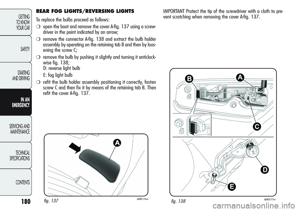
REAR FOG LIGHTS/REVERSING LIGHTS
To replace the bulbs proceed as follows:
❍open the boot and remove the cover A-fig. 137 using a screw-
driver in the point indicated by an arrow;
❍remove the connector A-fig. 138 and extract the bulb holder
assembly by operating on the retaining tab B and then by loos-
ening the screw C;
❍remove the bulb by pushing it slightly and turning it anticlock-
wise fig. 138;
D: reverse light bulb
E: fog light bulb
❍refit the bulb holder assembly positioning it correctly, fasten
screw C and then fix it by means of the retaining tab B. Then
refit the cover A-fig. 137.
fig. 137A0K0176mfig. 138A0K0177m
IMPORTANT Protect the tip of the screwdriver with a cloth to pre-
vent scratching when removing the cover A-fig. 137.
Page 185 of 297
181
GETTING
TO KNOW
YOUR CAR
SAFETY
STARTING
AND DRIVING
IN AN
EMERGENCY
SERVICING AND
MAINTENANCE
TECHNICAL
SPECIFICATIONS
CONTENTS
THIRD BRAKE LIGHTS
These are LEDs and are located on the spoiler integrated on the
boot hatch. Contact Alfa Romeo Authorized Services to replace these
lights.
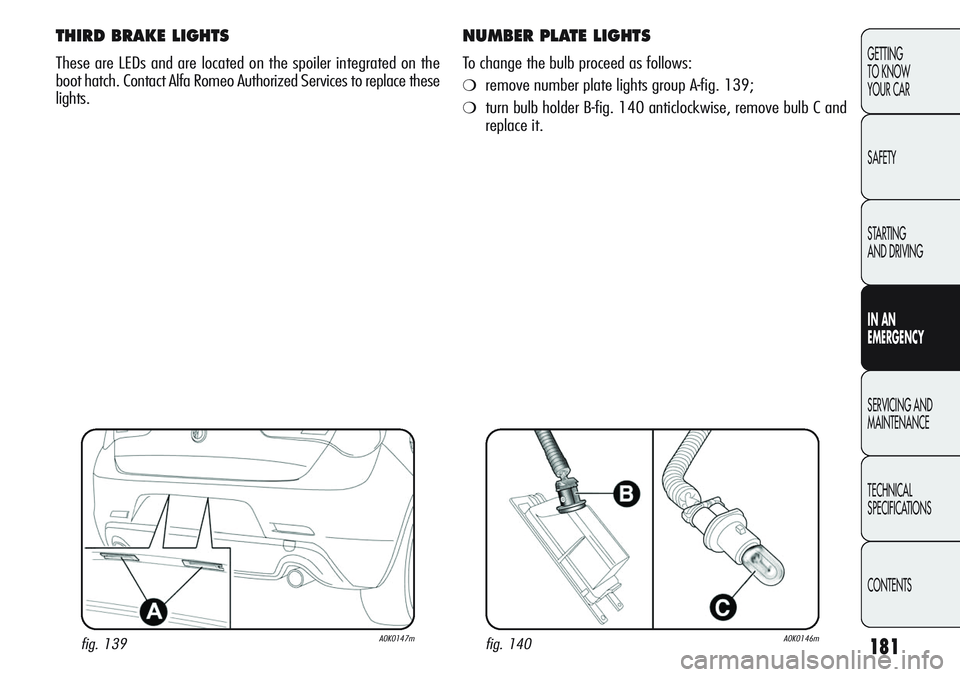
NUMBER PLATE LIGHTS
To change the bulb proceed as follows:
❍remove number plate lights group A-fig. 139;
❍turn bulb holder B-fig. 140 anticlockwise, remove bulb C and
replace it.
fig. 139A0K0147mfig. 140A0K0146m
Page 187 of 297
183
GETTING
TO KNOW
YOUR CAR
SAFETY
STARTING
AND DRIVING
IN AN
EMERGENCY
SERVICING AND
MAINTENANCE
TECHNICAL
SPECIFICATIONS
CONTENTS
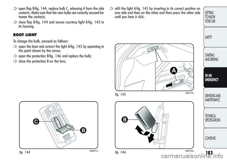
❍open flap B-fig. 144, replace bulb C, releasing it from the side
contacts. Make sure that the new bulbs are correctly secured be-
tween the contacts;
❍close flap B-fig. 144 and secure courtesy light A-fig. 143 in
its housing.
BOOT LIGHT
To change the bulb, proceed as follows:
❍open the boot and extract the light A-fig. 145 by operating in
the point shown by the arrow;
❍open the protection B-fig. 146 and replace the bulb;
❍close the protection B on the lens;
❍refit the light A-fig. 145 by inserting in its correct position on
one side and then on the other and then press the other side
until you hear it click.
fig. 146A0K0148m
fig. 145A0K0173m
fig. 144A0K0091m
Page 192 of 297
188
GETTING
TO KNOW
YOUR CAR
SAFETY
STARTING
AND DRIVING
IN AN
EMERGENCY
SERVICING AND
MAINTENANCE
TECHNICAL
SPECIFICATIONS
CONTENTS
If you have to wash the engine compart-
ment, take care not to aim the jet of wa-
ter directly at the fuse box or windscreen
wiper motors.
FUSE LOCATION
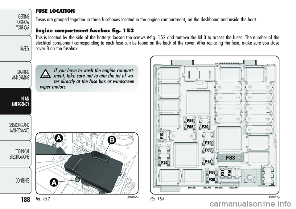
Fuses are grouped together in three fuseboxes located in the engine compartment, on the dashboard and inside the boot.
Engine compartment fusebox fig. 153
This is located by the side of the battery: loosen the screws A-fig. 152 and remove the lid B to access the fuses. The number of the
electrical component corresponding to each fuse can be found on the back of the cover. After replacing the fuse, make sure you close
cover B on the fusebox.
fig. 152A0K0174mfig. 153A0K0231m
Page 194 of 297
190
GETTING
TO KNOW
YOUR CAR
SAFETY
STARTING
AND DRIVING
IN AN
EMERGENCY
SERVICING AND
MAINTENANCE
TECHNICAL
SPECIFICATIONS
CONTENTS
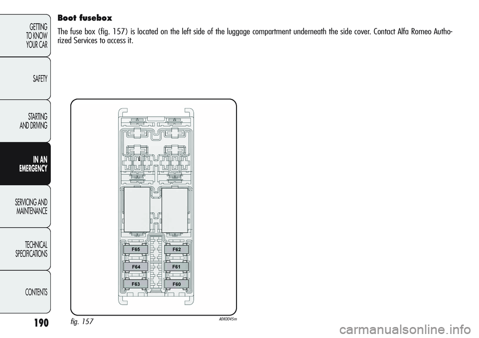
Boot fusebox
The fuse box (fig. 157) is located on the left side of the luggage compartment underneath the side cover. Contact Alfa Romeo Autho-
rized Services to access it.
fig. 157A0K0045m