roof Alfa Romeo Giulietta 2012 Owner handbook (in English)
[x] Cancel search | Manufacturer: ALFA ROMEO, Model Year: 2012, Model line: Giulietta, Model: Alfa Romeo Giulietta 2012Pages: 297, PDF Size: 9.37 MB
Page 2 of 297
We really know your car because we invented, designed and built it: we really know every single detail.
At Alfa Romeo Service authorised workshopsyou can find technicians directly trained by us,
offering quality and professionalism for all service operations.
Alfa Romeo workshops are always close to you for the regular servicing operations, season checks
and practical recommendations by our experts.
With Alfa Romeo Genuine Parts you keep the reliability, comfort and performance features
of your new car unchanged in time: that's why you bought it for.
Always ask for Genuine Parts for the components used on our cars; we recommend them because
they come from our steady commitment in research and development of highly innovative technologies.
For all these reasons: rely on Genuine Parts, because they are the only ones
designed by Alfa Romeo for your car.
SAFETY:
BRAKING SYSTEMENVIRONMENT: PARTICULATE FILTERS,
CLIMATE CONTROL MAINTENANCECOMFORT: SUSPENSION
AND WINDSCREEN WIPERS PERFORMANCE: SPARK PLUGS,
INJECTORS AND BATTERIESLINEACCESSORI
ROOF RACK BARS, WHEEL RIMS
WHY CHOOSING
GENUINE PARTS
Cop Alfa Giulietta GB:Alfa 159 cop. LUM GB 15-09-2011 15:08 Pagina 2
Page 52 of 297

48
GETTING
TO KNOW
YOUR CAR
SAFETY
STARTING
AND DRIVING
IN AN
EMERGENCY
SERVICING AND
MAINTENANCE
TECHNICAL
SPECIFICATIONS
CONTENTS
SWITCHING OFF THE ALARM
PressËbutton. The following operations are performed (exclud-
ing specific markets):
❍the direction indicators flash twice;
❍two brief acoustic signals are emitted;
❍the doors are unlocked.
IMPORTANT Activating the central opening using the key metal
insert the alarm does not turn off.
VOLUMETRIC/ANTI-LIFT PROTECTION
To guarantee the correct operation of the protection, completely
close the side windows and sunroof (for versions/markets, where
provided).
To disable the function, press A button fig. 20 before switching
on the alarm. The deactivation of the function is indicated by the
LED on A button flashing for several seconds.
The volume sensing/anti-tilt protection disabling procedure must
be repeated each time the key is turned off.
EXCLUDING THE ALARM
To permanently disable the alarm (e.g. for long storage of the car),
lock the car by turning the metal insert of the key with remote con-
trol in the lock.
IMPORTANT If the battery of the key with the remote control run
out or the system fails, the alarm can be switched off by placing
the key in the ignition switch and turning it to MAR.
fig. 20A0K0130m
Page 96 of 297
92
GETTING
TO KNOW
YOUR CAR
SAFETY
STARTING
AND DRIVING
IN AN
EMERGENCY
SERVICING AND
MAINTENANCE
TECHNICAL
SPECIFICATIONS
CONTENTS
ELECTRIC SUN ROOF
(for versions/markets, where provided)
The sun roof comprises two glass panels; the front one is mobile
and the rear one fixed. These are equipped with two sun blinds
(front and rear) that can be moved manually. With the sun roof
closed, the blinds can be placed in any position.
OPERATION
The sunroof can be operated only with the ignition key turned to
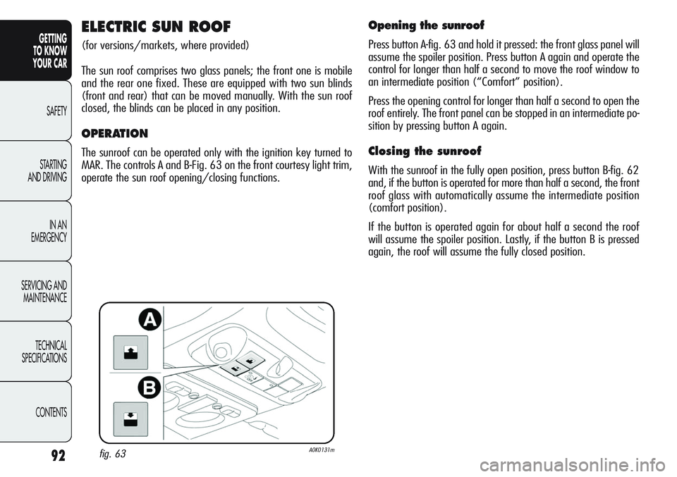
MAR. The controls A and B-Fig. 63 on the front courtesy light trim,
operate the sun roof opening/closing functions.
Opening the sunroof
Press button A-fig. 63 and hold it pressed: the front glass panel will
assume the spoiler position. Press button A again and operate the
control for longer than half a second to move the roof window to
an intermediate position (“Comfort” position).
Press the opening control for longer than half a second to open the
roof entirely. The front panel can be stopped in an intermediate po-
sition by pressing button A again.
Closing the sunroof
With the sunroof in the fully open position, press button B-fig. 62
and, if the button is operated for more than half a second, the front
roof glass with automatically assume the intermediate position
(comfort position).
If the button is operated again for about half a second the roof
will assume the spoiler position. Lastly, if the button B is pressed
again, the roof will assume the fully closed position.
fig. 63A0K0131m
Page 97 of 297
93
GETTING
TO KNOW
YOUR CAR
SAFETY
STARTING
AND DRIVING
IN AN
EMERGENCY
SERVICING AND
MAINTENANCE
TECHNICAL
SPECIFICATIONS
CONTENTSWhen leaving the car, always remove the key from
the ignition device to avoid the risk of injury due
to accidental operation of the sun roof; it presents
a risk to those left on board: improper use of the roof
can be dangerous. Before round during operation, always
check that no-one is at risk of being injured by the mov-
ing sunroof or by objects getting caught and dragged
by it.
Do not open the sun roof in the presence of snow
or ice: it may be damaged.
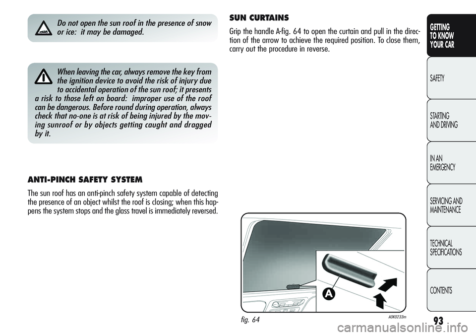
fig. 64A0K0233m
SUN CURTAINS
Grip the handle A-fig. 64 to open the curtain and pull in the direc-
tion of the arrow to achieve the required position. To close them,
carry out the procedure in reverse.
ANTI-PINCH SAFETY SYSTEM
The sun roof has an anti-pinch safety system capable of detecting
the presence of an object whilst the roof is closing; when this hap-
pens the system stops and the glass travel is immediately reversed.
Page 98 of 297
94
GETTING
TO KNOW
YOUR CAR
SAFETY
STARTING
AND DRIVING
IN AN
EMERGENCY
SERVICING AND
MAINTENANCE
TECHNICAL
SPECIFICATIONS
CONTENTS
MAINTENANCE/EMERGENCY
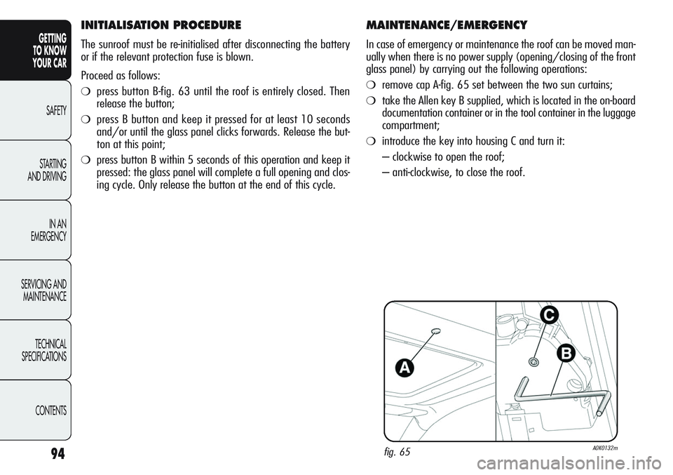
In case of emergency or maintenance the roof can be moved man-
ually when there is no power supply (opening/closing of the front
glass panel) by carrying out the following operations:
❍remove cap A-fig. 65 set between the two sun curtains;
❍take the Allen key B supplied, which is located in the on-board
documentation container or in the tool container in the luggage
compartment;
❍introduce the key into housing C and turn it:
– clockwise to open the roof;
– anti-clockwise, to close the roof.
fig. 65A0K0132m
INITIALISATION PROCEDURE
The sunroof must be re-initialised after disconnecting the battery
or if the relevant protection fuse is blown.
Proceed as follows:
❍press button B-fig. 63 until the roof is entirely closed. Then
release the button;
❍press B button and keep it pressed for at least 10 seconds
and/or until the glass panel clicks forwards. Release the but-
ton at this point;
❍press button B within 5 seconds of this operation and keep it
pressed: the glass panel will complete a full opening and clos-
ing cycle. Only release the button at the end of this cycle.
Page 111 of 297
107
GETTING
TO KNOW
YOUR CAR
SAFETY
STARTING
AND DRIVING
IN AN
EMERGENCY
SERVICING AND
MAINTENANCE
TECHNICAL
SPECIFICATIONS
CONTENTS
ROOF RACK/SKI RACK
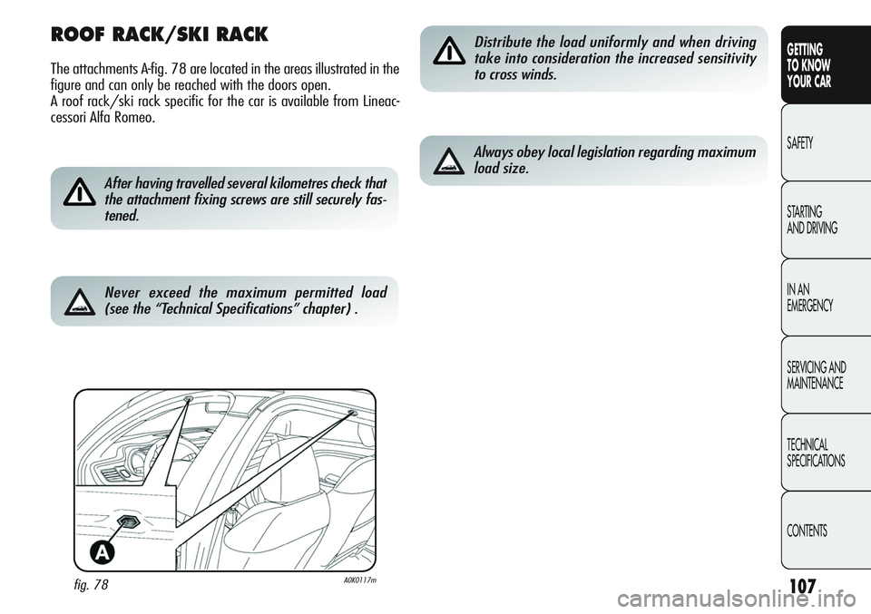
The attachments A-fig. 78 are located in the areas illustrated in the
figure and can only be reached with the doors open.
A roof rack/ski rack specific for the car is available from Lineac-
cessori Alfa Romeo.
fig. 78A0K0117m
After having travelled several kilometres check that
the attachment fixing screws are still securely fas-
tened.
Distribute the load uniformly and when driving
take into consideration the increased sensitivity
to cross winds.
Always obey local legislation regarding maximum
load size.
Never exceed the maximum permitted load
(see the “Technical Specifications” chapter) .
Page 126 of 297
122
GETTING
TO KNOW
YOUR CAR
SAFETY
STARTING
AND DRIVING
IN AN
EMERGENCY
SERVICING AND
MAINTENANCE
TECHNICAL
SPECIFICATIONS
CONTENTS
CAR RADIO SET-UP
(for versions/markets, where provided)
If no car radio was requested at the time of purchase, the vehicle
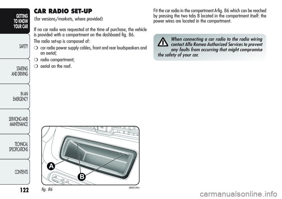
is provided with a compartment on the dashboard fig. 86.
The radio set-up is composed of:
❍car radio power supply cables, front and rear loudspeakers and
an aerial;
❍radio compartment;
❍aerial on the roof.
fig. 86A0K0134m
Fit the car radio in the compartment A-fig. 86 which can be reached
by pressing the two tabs B located in the compartment itself: the
power wires are located in the compartment.
When connecting a car radio to the radio wiring
contact Alfa Romeo Authorized Services to prevent
any faults from occurring that might compromise
the safety of your car.
Page 128 of 297

124
GETTING
TO KNOW
YOUR CAR
SAFETY
STARTING
AND DRIVING
IN AN
EMERGENCY
SERVICING AND
MAINTENANCE
TECHNICAL
SPECIFICATIONS
CONTENTS
RADIO TRANSMITTERS AND CELLULAR PHONES
Radio transmitting equipment (vehicle mobile phones, CB radios,
amateur radio etc.) shall not be used inside the car unless a sep-
arate aerial is mounted on the roof.
IMPORTANT The use of these devices inside the passenger com-
partment (without a separate aerial) may cause the vehicle elec-
trical systems to malfunction. This could compromise safety in ad-
dition to constituting a potential hazard for passengers’ health.
In addition, transmission and reception of these devices may be af-
fected by the shielding effect of the car body. As far as the use of
EC-approved mobile phones is concerned (GSM, GPRS, UMTS), fol-
low the instructions for use provided by the mobile phone manu-
facturer.
PARKING SENSORS
(for versions/markets, where provided)
The parking sensors are located on the rear bumper fig. 88 and
their function is to inform the driver, through an intermittent beep-
ing, of the presence of obstacles behind the car.
TURNING THE SENSORS ON
The sensors are turned on when reverse gear is engaged. As the
distance from the obstacle behind the car decreases, the beeping
becomes more frequent.
fig. 88A0K0060m
Page 152 of 297
148
GETTING
TO KNOW
YOUR CAR
SAFETY
STARTING
AND DRIVING
IN AN
EMERGENCY
SERVICING AND
MAINTENANCE
TECHNICAL
SPECIFICATIONS
CONTENTS
SIDE AIR BAGS
(SIDE BAG - WINDOW BAG)
The car is fitted with front side bags for driver and passenger for
protecting the chest, and window bags for protecting front and rear
passengers’ heads.
Side bags protect car occupants from side crashes of medium-high
severity, by placing the cushion between the occupant and the in-
ternal parts of the side structure of the car.
Non-activation of side bags in other types of collisions (front colli-
sions, rear shunts, roll-overs, etc...) is not a system malfunction.
fig. 108A0K0081mfig. 109A0K0035m
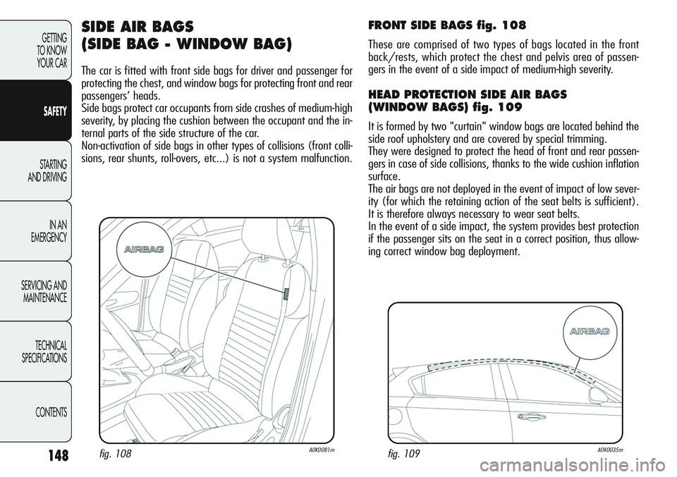
FRONT SIDE BAGS fig. 108
These are comprised of two types of bags located in the front
back/rests, which protect the chest and pelvis area of passen-
gers in the event of a side impact of medium-high severity.
HEAD PROTECTION SIDE AIR BAGS
(WINDOW BAGS) fig. 109
It is formed by two "curtain" window bags are located behind the
side roof upholstery and are covered by special trimming.
They were designed to protect the head of front and rear passen-
gers in case of side collisions, thanks to the wide cushion inflation
surface.
The air bags are not deployed in the event of impact of low sever-
ity (for which the retaining action of the seat belts is sufficient).
It is therefore always necessary to wear seat belts.
In the event of a side impact, the system provides best protection
if the passenger sits on the seat in a correct position, thus allow-
ing correct window bag deployment.
Page 159 of 297
155
GETTING
TO KNOW
YOUR CAR
SAFETY
STARTING
AND DRIVING
IN AN
EMERGENCY
SERVICING AND
MAINTENANCE
TECHNICAL
SPECIFICATIONS
CONTENTS
SAVING FUEL
Here are some suggestions which may help you to save fuel and
lower the amount of harmful emissions released into the atmos-
phere.
GENERAL CONSIDERATIONS
Car maintenance
Have checks and adjustments carried out in accordance with the
“Scheduled Servicing Plan” (see chapter “Servicing and mainte-
nance”).
Tyres
Check the tyre pressure at least once every 4 weeks: if the pres-
sure is too low, consumption levels increase as resistance to rolling
is higher.
Unnecessar y loads
Do not travel with an overloaded boot. The weight of the car and
its arrangement greatly affect fuel consumption and stability.
Roof rack/ski rack
Remove the roof rack or the ski rack from the roof after use. These
accessories decrease aerodynamic penetration and have a nega-
tive effect on fuel consumption. It is better to use a trailer to trans-
port particularly bulky objects.
Electric devices
Use electric devices only for the amount of time needed. The heat-
ed rear windscreen, additional headlights, windscreen wipers and
heater fan require a considerable amount of energy; increasing the
current uptake increases fuel consumption (by up to +25% in an
urban cycle).
Climate control system
Using the climate control system will increase consumption: use
the air vents when the external temperature so allows.
Spoilers
The use of non-certified spoilers may adversely affect aerodynam-
ics and fuel consumption.