fuse Alfa Romeo Giulietta 2017 Owner's Manual
[x] Cancel search | Manufacturer: ALFA ROMEO, Model Year: 2017, Model line: Giulietta, Model: Alfa Romeo Giulietta 2017Pages: 212, PDF Size: 4.56 MB
Page 13 of 212
ALARMSYSTEM
(for versions/markets, where provided)
ALARM ACTIVATION
Activation of the alarm triggers the
acoustic warning and the direction
indicators.
IMPORTANT The alarm is adapted by the
Manufacturer to meet the requirements
of the various countries where the
vehicle is marketed.
SWITCHING ON THE ALARM
With the doors, bonnet and tailgate
closed and the ignition key either turned
to STOP or removed, point the key with
remote control towards the car and press
and release the button
.
Except on some versions for specific
markets, the system produces a visual
and acoustic warning and enables door
locking.
ALARM SELF-ACTIVATION(for versions/markets, where provided)
If the alarm has not been activated using
the remote control, approximately
30 seconds after the key is turned to the
STOP position and the last time one of
the doors or tailgate was opened and
reclosed, the alarm is activated
automatically.This condition is indicated by the
intermittent illumination of the LED on
the alarm deactivation button on the roof
light and by the activation indications
described previously.
To deactivate the alarm, press the button
on the remote control.
Alarm self-activation also occurs when
the doors are closed by turning the metal
insert of the key in the driver door lock. If
the alarm is self-activated, the doors will
not be locked.
TURNING THE ALARM OFF
IMPORTANT Activating the central
opening using the key's metal insert does
not turn the alarm off.
DOORS
DOOR CENTRAL LOCKING/UNLOCKING
Locking from the outside
With the doors closed, press the
button on the key or fit and then turn
the metal insert (located inside the key)
in the driver side door lock.
The door locking function is operated:
with all the doors closed;
with all the doors closed and boot
open.
Door unlocking from the outside
Press the
button on the key or turn the
metal insert (located inside the key) in
the driver side door lock.
Door locking/unlocking from the inside
Press the
button on the dashboard.
IMPORTANT With central locking active,
pulling the internal opening lever of the
passenger side door unlocks the door
itself. Pulling the internal opening lever
of the driver side door activates central
unlocking.
IMPORTANT The rear doors cannot be
opened from the inside when the child
lock device is engaged.
In the absence of electrical power supply
(e.g. blown fuse, battery disconnected,
etc.) it is still possible to lock the doors
manually.
11
Page 14 of 212
CHILD SAFETY DEVICE
This system prevents the rear doors from
being opened from the inside.
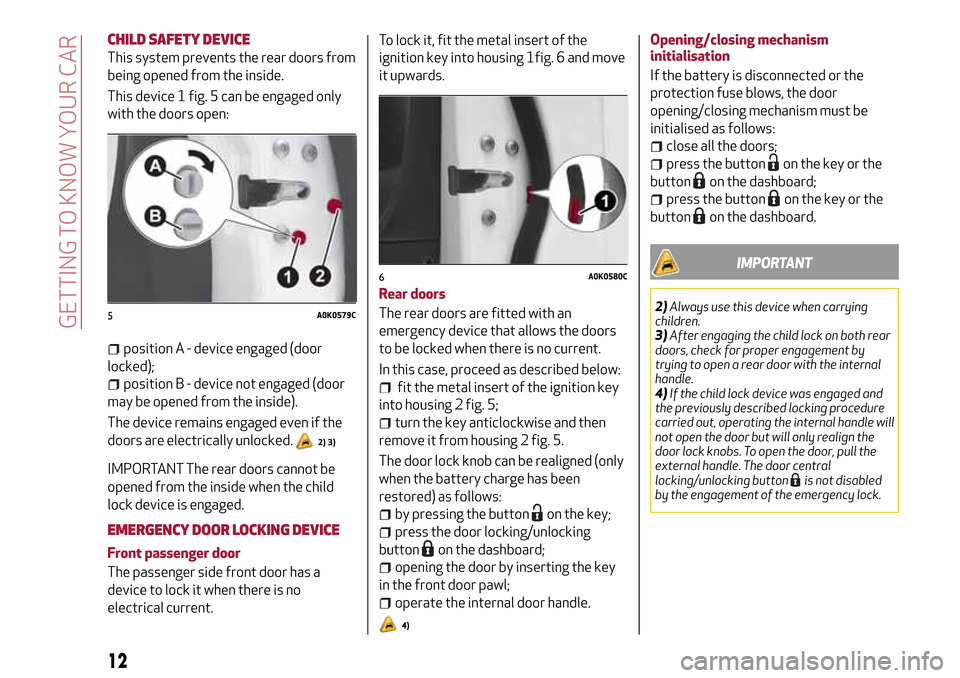
This device 1 fig. 5 can be engaged only
with the doors open:
position A - device engaged (door
locked);
position B - device not engaged (door
may be opened from the inside).
The device remains engaged even if the
doors are electrically unlocked.
2) 3)
IMPORTANT The rear doors cannot be
opened from the inside when the child
lock device is engaged.
EMERGENCY DOOR LOCKING DEVICE
Front passenger door
The passenger side front door has a
device to lock it when there is no
electrical current.To lock it, fit the metal insert of the
ignition key into housing 1fig. 6 and move
it upwards.
Rear doors
The rear doors are fitted with an
emergency device that allows the doors
to be locked when there is no current.
In this case, proceed as described below:
fit the metal insert of the ignition key
into housing 2 fig. 5;
turn the key anticlockwise and then
remove it from housing 2 fig. 5.
The door lock knob can be realigned (only
when the battery charge has been
restored) as follows:
by pressing the buttonon the key;
press the door locking/unlocking
button
on the dashboard;
opening the door by inserting the key
in the front door pawl;
operate the internal door handle.
4)
Opening/closing mechanism
initialisation
If the battery is disconnected or the
protection fuse blows, the door
opening/closing mechanism must be
initialised as follows:
close all the doors;
press the buttonon the key or the
button
on the dashboard;
press the buttonon the key or the
button
on the dashboard.
IMPORTANT
2)Always use this device when carrying
children.
3)After engaging the child lock on both rear
doors, check for proper engagement by
trying to open a rear door with the internal
handle.
4)If the child lock device was engaged and
the previously described locking procedure
carried out, operating the internal handle will
not open the door but will only realign the
door lock knobs. To open the door, pull the
external handle. The door central
locking/unlocking button
is not disabled
by the engagement of the emergency lock.
5A0K0579C
6A0K0580C
12
GETTING TO KNOW YOUR CAR
Page 25 of 212
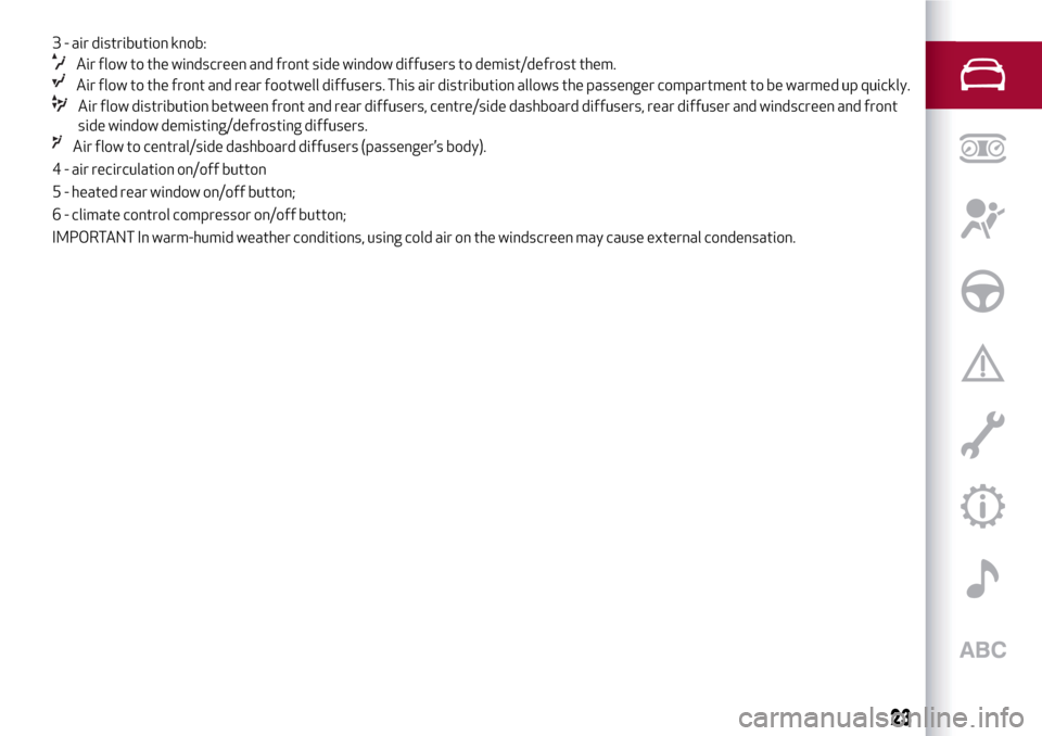
3 - air distribution knob:
Air flow to the windscreen and front side window diffusers to demist/defrost them.
Air flow to the front and rear footwell diffusers. This air distribution allows the passenger compartment to be warmed up quickly.
Air flow distribution between front and rear diffusers, centre/side dashboard diffusers, rear diffuser and windscreen and front
side window demisting/defrosting diffusers.
Air flow to central/side dashboard diffusers (passenger’s body).
4 - air recirculation on/off button
5 - heated rear window on/off button;
6 - climate control compressor on/off button;
IMPORTANT In warm-humid weather conditions, using cold air on the windscreen may cause external condensation.
23
Page 28 of 212
ELECTRIC WINDOWS
These operate when the ignition key is
turned to MAR and for about 3 minutes
after turning the key to STOP or
removing it if one of the front doors is
open.
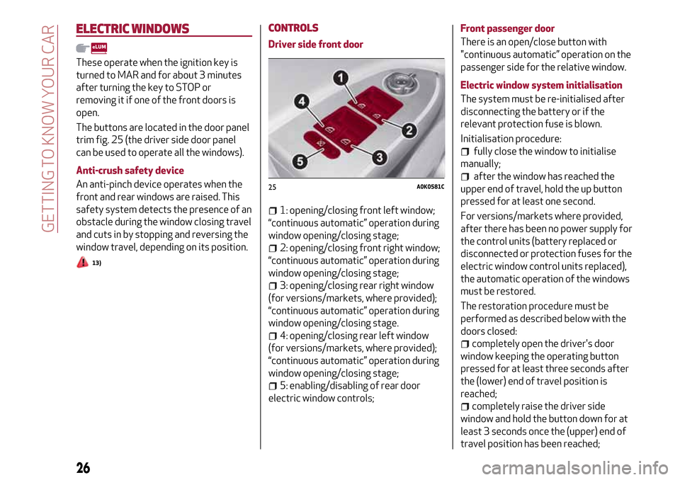
The buttons are located in the door panel
trim fig. 25 (the driver side door panel
can be used to operate all the windows).
Anti-crush safety device
An anti-pinch device operates when the
front and rear windows are raised. This
safety system detects the presence of an
obstacle during the window closing travel
and cuts in by stopping and reversing the
window travel, depending on its position.
13)
CONTROLS
Driver side front door
1: opening/closing front left window;
“continuous automatic” operation during
window opening/closing stage;
2: opening/closing front right window;
“continuous automatic” operation during
window opening/closing stage;
3: opening/closing rear right window
(for versions/markets, where provided);
“continuous automatic” operation during
window opening/closing stage.
4: opening/closing rear left window
(for versions/markets, where provided);
“continuous automatic” operation during
window opening/closing stage;
5: enabling/disabling of rear door
electric window controls;Front passenger door
There is an open/close button with
"continuous automatic” operation on the
passenger side for the relative window.
Electric window system initialisation
The system must be re-initialised after
disconnecting the battery or if the
relevant protection fuse is blown.
Initialisation procedure:
fully close the window to initialise
manually;
after the window has reached the
upper end of travel, hold the up button
pressed for at least one second.
For versions/markets where provided,
after there has been no power supply for
the control units (battery replaced or
disconnected or protection fuses for the
electric window control units replaced),
the automatic operation of the windows
must be restored.
The restoration procedure must be
performed as described below with the
doors closed:
completely open the driver's door
window keeping the operating button
pressed for at least three seconds after
the (lower) end of travel position is
reached;
completely raise the driver side
window and hold the button down for at
least 3 seconds once the (upper) end of
travel position has been reached;
25A0K0581C
26
GETTING TO KNOW YOUR CAR
Page 30 of 212
To close them, carry out the procedure in
reverse.
INITIALISATION PROCEDURE
The sunroof must be re-initialised after
disconnecting the battery or if the
relevant protection fuse is blown.
Proceed as follows:
press button 1 fig. 26 until the roof is
completely closed. Then release the
button;
press button 2 and hold it down for at
least 10 seconds and/or until the glass
panel clicks forwards. Release the button
at this point;
within 5 seconds of the previous
operation, press button 2 and hold it
down: the front glass panel will complete
a full opening and closing cycle. Only
release the button at the end of this
cycle.
MAINTENANCE/EMERGENCY
In case of emergency or maintenance the
roof can be moved manually when there
is no power supply (opening/closing of
the front glass panel) by carrying out the
following operations:
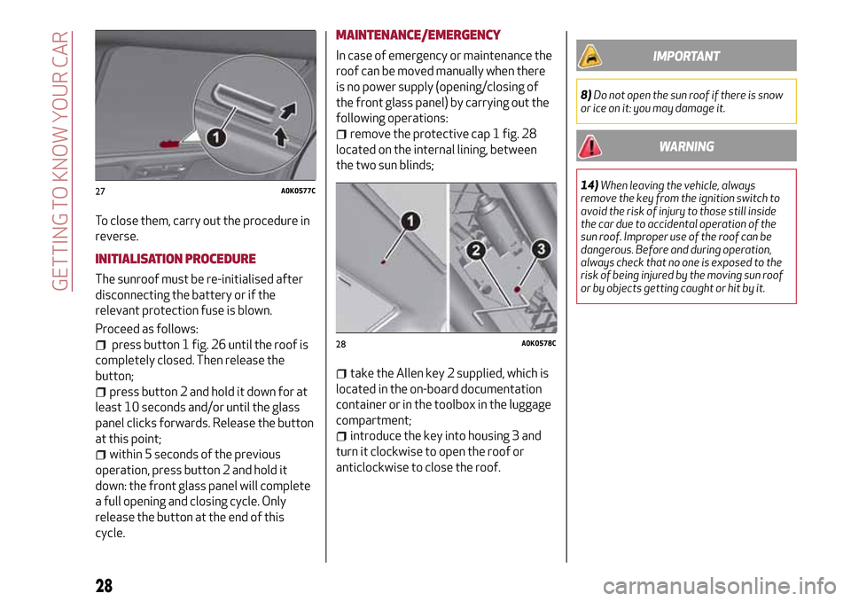
remove the protective cap 1 fig. 28
located on the internal lining, between
the two sun blinds;
take the Allen key 2 supplied, which is
located in the on-board documentation
container or in the toolbox in the luggage
compartment;
introduce the key into housing 3 and
turn it clockwise to open the roof or
anticlockwise to close the roof.
IMPORTANT
8)Do not open the sun roof if there is snow
or ice on it: you may damage it.
WARNING
14)When leaving the vehicle, always
remove the key from the ignition switch to
avoid the risk of injury to those still inside
the car due to accidental operation of the
sun roof. Improper use of the roof can be
dangerous. Before and during operation,
always check that no one is exposed to the
risk of being injured by the moving sun roof
or by objects getting caught or hit by it.27A0K0577C
28A0K0578C
28
GETTING TO KNOW YOUR CAR
Page 32 of 212
BOOT
The luggage compartment unlocking is
electrically operated and is deactivated
when the car is in motion.
OPENING
When unlocked, the luggage
compartment can be opened from
outside the car by pressing the electric
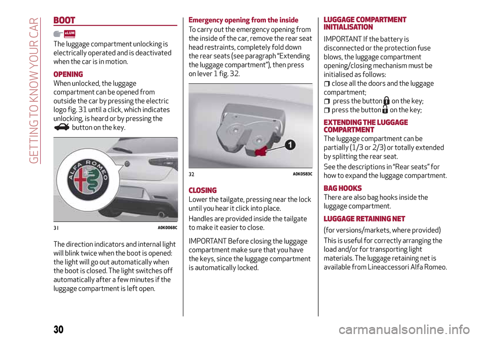
logo fig. 31 until a click, which indicates
unlocking, is heard or by pressing the
button on the key.
The direction indicators and internal light
will blink twice when the boot is opened:
the light will go out automatically when
the boot is closed. The light switches off
automatically after a few minutes if the
luggage compartment is left open.Emergency opening from the inside
To carry out the emergency opening from
the inside of the car, remove the rear seat
head restraints, completely fold down
the rear seats (see paragraph “Extending
the luggage compartment”), then press
on lever 1 fig. 32.
CLOSING
Lower the tailgate, pressing near the lock
until you hear it click into place.
Handles are provided inside the tailgate
to make it easier to close.
IMPORTANT Before closing the luggage
compartment make sure that you have
the keys, since the luggage compartment
is automatically locked.LUGGAGE COMPARTMENT
INITIALISATION
IMPORTANT If the battery is
disconnected or the protection fuse
blows, the luggage compartment
opening/closing mechanism must be
initialised as follows:
close all the doors and the luggage
compartment;
press the buttonon the key;
press the buttonon the key;
EXTENDING THE LUGGAGE
COMPARTMENT
The luggage compartment can be
partially (1/3 or 2/3) or totally extended
by splitting the rear seat.
See the descriptions in “Rear seats” for
how to expand the luggage compartment.
BAG HOOKS
There are also bag hooks inside the
luggage compartment.
LUGGAGE RETAINING NET
(for versions/markets, where provided)
This is useful for correctly arranging the
load and/or for transporting light
materials. The luggage retaining net is
available from Lineaccessori Alfa Romeo.31A0K0068C
32A0K0583C
30
GETTING TO KNOW YOUR CAR
Page 57 of 212
Symbol on the display What it means What to do
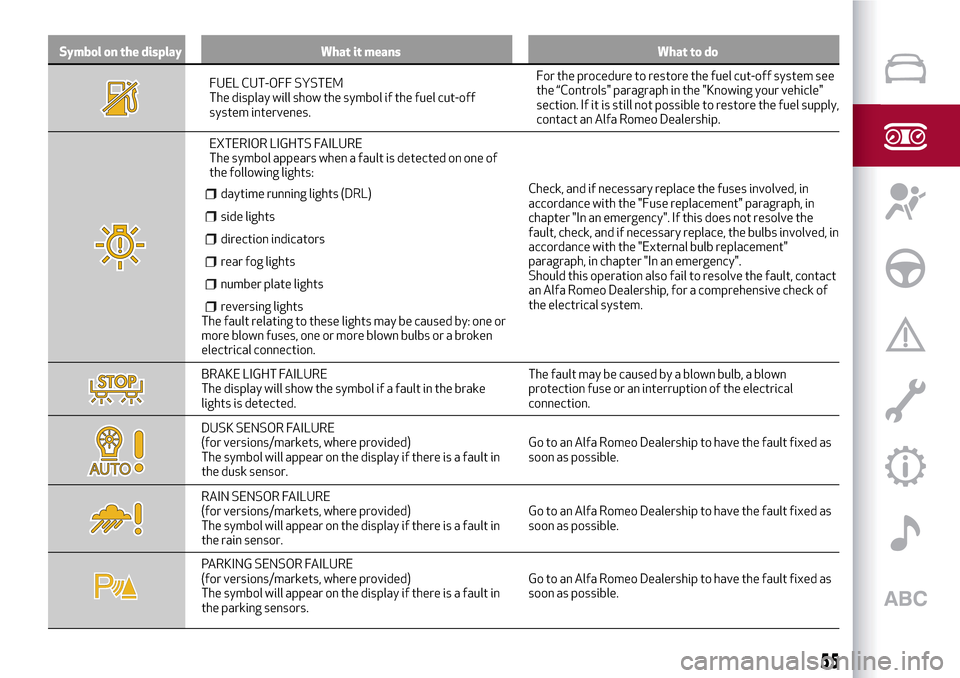
FUEL CUT-OFF SYSTEM
The display will show the symbol if the fuel cut-off
system intervenes.For the procedure to restore the fuel cut-off system see
the “Controls" paragraph in the "Knowing your vehicle"
section. If it is still not possible to restore the fuel supply,
contact an Alfa Romeo Dealership.
EXTERIOR LIGHTS FAILURE
The symbol appears when a fault is detected on one of
the following lights:
daytime running lights (DRL)
side lights
direction indicators
rear fog lights
number plate lights
reversing lightsThe fault relating to these lights may be caused by: one or
more blown fuses, one or more blown bulbs or a broken
electrical connection.Check, and if necessary replace the fuses involved, in
accordance with the "Fuse replacement" paragraph, in
chapter "In an emergency". If this does not resolve the
fault, check, and if necessary replace, the bulbs involved, in
accordance with the "External bulb replacement"
paragraph, in chapter "In an emergency".
Should this operation also fail to resolve the fault, contact
an Alfa Romeo Dealership, for a comprehensive check of
the electrical system.
BRAKE LIGHT FAILURE
The display will show the symbol if a fault in the brake
lights is detected.The fault may be caused by a blown bulb, a blown
protection fuse or an interruption of the electrical
connection.
DUSK SENSOR FAILURE
(for versions/markets, where provided)
The symbol will appear on the display if there is a fault in
the dusk sensor.Go to an Alfa Romeo Dealership to have the fault fixed as
soon as possible.
RAIN SENSOR FAILURE
(for versions/markets, where provided)
The symbol will appear on the display if there is a fault in
the rain sensor.Go to an Alfa Romeo Dealership to have the fault fixed as
soon as possible.
PARKING SENSOR FAILURE
(for versions/markets, where provided)
The symbol will appear on the display if there is a fault in
the parking sensors.Go to an Alfa Romeo Dealership to have the fault fixed as
soon as possible.
55
Page 97 of 212
A punctured tyre or a burnt-out bulb?
At times, a problem may interfere with our journey.
The pages on emergencies can help you to deal with critical
situations independently and with calm. In an emergency we
recommend that you call the freephone number found in the
Warranty Booklet. You can also use the universal, national or
international freephone number to find your nearest Authorised
Alfa Romeo Dealership.
IN AN EMERGENCY
HAZARD WARNING LIGHTS........................96
REPLACING A BULB.............................96
REPLACING AN EXTERIOR BULB....................100
REPLACING FUSES............................102
CHANGING A WHEEL ...........................110
FIX&GO KIT.................................113
JUMP STARTING..............................116
FUEL CUT-OFF SYSTEM . ........................117
TCT TRANSMISSION - KEY REMOVAL.................117
TOWING THE CAR.............................119
Page 98 of 212
HAZARD WARNING LIGHTS
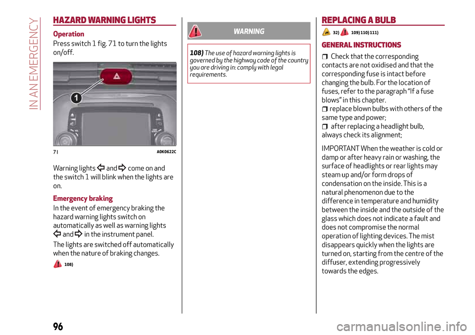
Operation
Press switch 1 fig. 71 to turn the lights
on/off.
Warning lights
andcome on and
the switch 1 will blink when the lights are
on.
Emergency braking
In the event of emergency braking the
hazard warning lights switch on
automatically as well as warning lights
andin the instrument panel.
The lights are switched off automatically
when the nature of braking changes.
108)
WARNING
108)The use of hazard warning lights is
governed by the highway code of the country
you are driving in: comply with legal
requirements.
REPLACING A BULB
32)109) 110) 111)
GENERAL INSTRUCTIONS
Check that the corresponding
contacts are not oxidised and that the
corresponding fuse is intact before
changing the bulb. For the location of
fuses, refer to the paragraph “If a fuse
blows” in this chapter.
replace blown bulbs with others of the
same type and power;
after replacing a headlight bulb,
always check its alignment;
IMPORTANT When the weather is cold or
damp or after heavy rain or washing, the
surface of headlights or rear lights may
steam up and/or form drops of
condensation on the inside. This is a
natural phenomenon due to the
difference in temperature and humidity
between the inside and the outside of the
glass which does not indicate a fault and
does not compromise the normal
operation of lighting devices. The mist
disappears quickly when the lights are
turned on, starting from the centre of the
diffuser, extending progressively
towards the edges.71A0K0622C
96
IN AN EMERGENCY
Page 104 of 212
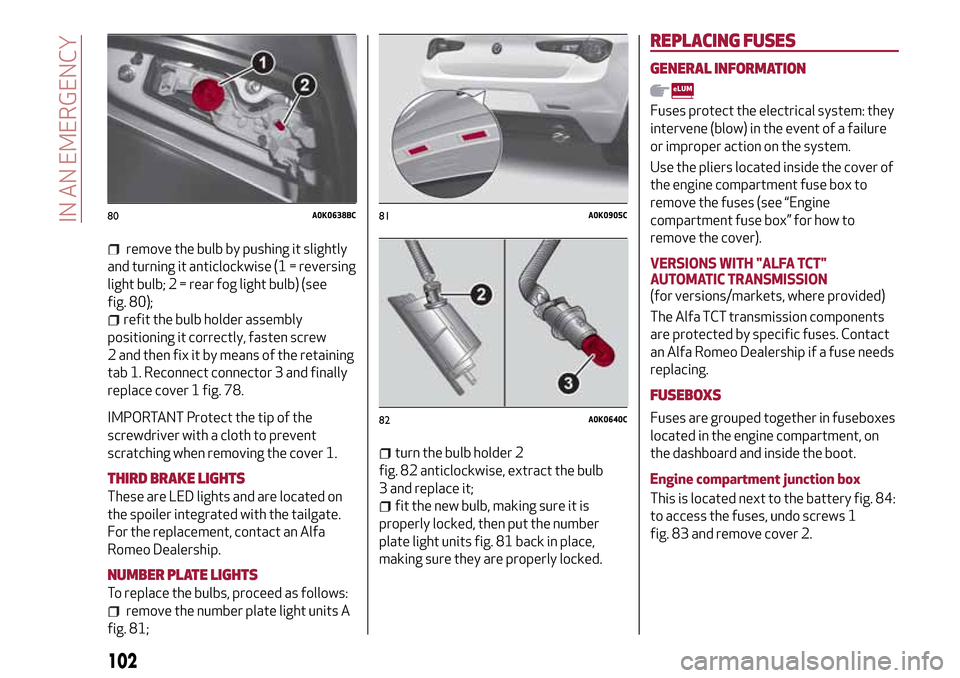
remove the bulb by pushing it slightly
and turning it anticlockwise (1 = reversing
light bulb; 2 = rear fog light bulb) (see
fig. 80);
refit the bulb holder assembly
positioning it correctly, fasten screw
2 and then fix it by means of the retaining
tab 1. Reconnect connector 3 and finally
replace cover 1 fig. 78.
IMPORTANT Protect the tip of the
screwdriver with a cloth to prevent
scratching when removing the cover 1.
THIRD BRAKE LIGHTS
These are LED lights and are located on
the spoiler integrated with the tailgate.
For the replacement, contact an Alfa
Romeo Dealership.
NUMBER PLATE LIGHTS
To replace the bulbs, proceed as follows:
remove the number plate light units A
fig. 81;
turn the bulb holder 2
fig. 82 anticlockwise, extract the bulb
3 and replace it;
fit the new bulb, making sure it is
properly locked, then put the number
plate light units fig. 81 back in place,
making sure they are properly locked.
REPLACING FUSES
GENERAL INFORMATION
Fuses protect the electrical system: they
intervene (blow) in the event of a failure
or improper action on the system.
Use the pliers located inside the cover of
the engine compartment fuse box to
remove the fuses (see “Engine
compartment fuse box” for how to
remove the cover).
VERSIONS WITH "ALFA TCT"
AUTOMATIC TRANSMISSION
(for versions/markets, where provided)
The Alfa TCT transmission components
are protected by specific fuses. Contact
an Alfa Romeo Dealership if a fuse needs
replacing.
FUSEBOXS
Fuses are grouped together in fuseboxes
located in the engine compartment, on
the dashboard and inside the boot.
Engine compartment junction box
This is located next to the battery fig. 84:
to access the fuses, undo screws 1
fig. 83 and remove cover 2.
80A0K0638BC81A0K0905C
82A0K0640C
102
IN AN EMERGENCY