ECO mode ALFA ROMEO STELVIO 2022 Owner's Guide
[x] Cancel search | Manufacturer: ALFA ROMEO, Model Year: 2022, Model line: STELVIO, Model: ALFA ROMEO STELVIO 2022Pages: 256, PDF Size: 10.17 MB
Page 150 of 256
SAFETY
148
Frontal Collision Alarm With Active Braking — If
Equipped
If this function is selected, the brakes are
operated to reduce the speed of the vehicle in the
event of potential frontal impact.
This function applies an additional braking
pressure if the braking pressure applied by the
driver does not suffice to prevent potential frontal
impact.
The function is active with speed above 2 mph
(4 km/h).
NOTE:
When using an automatic car wash it is recom-
mended to deactivate the system through the
settings of the radio system. The system may
detect the presence of a car, a wall or another
obstacle and activate.
Driving In Special Conditions
In certain driving conditions, system intervention
might be unexpected or delayed. The driver must
therefore be very careful, keeping control of the
vehicle to drive in complete safety.
Driving close to a bend.
The vehicle ahead is leaving a roundabout.
Vehicles with small dimensions and/or not
aligned in the driving lane.
Lane change by other vehicles.
Vehicles traveling at right angles to the vehicle.
NOTE:
In particularly complex traffic conditions, the
driver can deactivate the system manually
through the Information and Entertainment
system.
If the driver presses the brake pedal fully or
makes an excessive steering maneuver during
system operation, the automatic braking
function may deactivate (e.g. to allow a
possible maneuver to avoid the obstacle).
The FCW system is automatically deactivated
when operating in race mode and a warning
message will be displayed on the instrument
cluster.
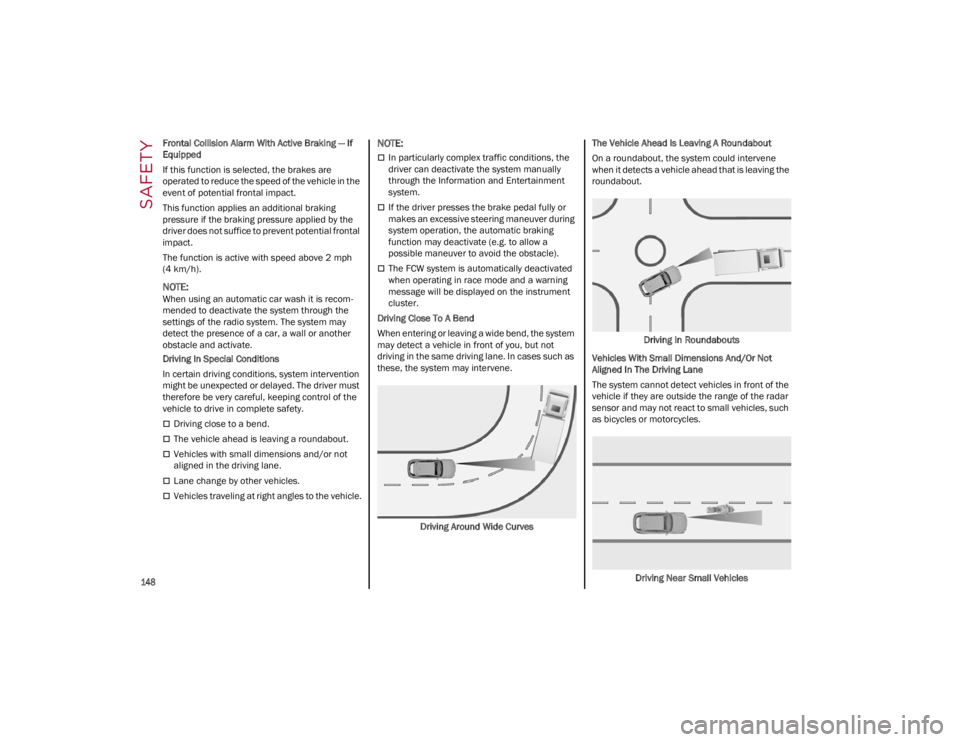
Driving Close To A Bend
When entering or leaving a wide bend, the system
may detect a vehicle in front of you, but not
driving in the same driving lane. In cases such as
these, the system may intervene.
Driving Around Wide Curves The Vehicle Ahead Is Leaving A Roundabout
On a roundabout, the system could intervene
when it detects a vehicle ahead that is leaving the
roundabout.
Driving In Roundabouts
Vehicles With Small Dimensions And/Or Not
Aligned In The Driving Lane
The system cannot detect vehicles in front of the
vehicle if they are outside the range of the radar
sensor and may not react to small vehicles, such
as bicycles or motorcycles.
Driving Near Small Vehicles
22_GU_OM_EN_USC_t.book Page 148
Page 153 of 256
151
To deactivate the TPMS, first replace all four
wheel and tire assemblies (road tires) with tires
not equipped with Tire Pressure Monitoring
System (TPMS) sensors. Then, drive the vehicle
for 20 minutes above 15 mph (24 km/h). The
TPMS will chime, the TPMS Warning Light will
flash on and off for 75 seconds and then remain
on. The instrument cluster will display the
“SERVICE TPM SYSTEM” message and then
display dashes (--) in place of the pressure values.
Beginning with the next ignition switch cycle, the
TPMS will no longer chime or display the
“SERVICE TPM SYSTEM” message in the
instrument cluster. Instead, dashes (--) will
remain in place of the pressure values.
To reactivate the TPMS, replace all four wheel
and tire assemblies (road tires) with tires
equipped with TPMS sensors. Then, drive the
vehicle for up to 20 minutes above 15 mph
(24 km/h). The TPMS will chime, the TPMS
Warning Light will flash on and off for 75 seconds
and then turn off. The instrument cluster will
display the “SERVICE TPM SYSTEM” message
and then display pressure values in place of the
dashes. On the next ignition switch cycle the
“SERVICE TPM SYSTEM” message will no longer
be displayed, as long as no system fault exists.
NOTE:
The TPMS is not intended to replace normal
tire care and maintenance, or to provide
warning of a tire failure or condition.
The TPMS should not be used as a tire
pressure gauge while adjusting your tire
pressure.
Driving on a significantly underinflated tire will
cause the tire to overheat, and can lead to tire
failure. Underinflation also reduces fuel efficiency and tire tread life, and may affect the
vehicle’s handling and stopping ability.
The TPMS is not a substitute for proper tire
maintenance, and it is the driver’s responsi
-
bility to maintain correct tire pressure using an
accurate tire pressure gauge, even if underin -
flation has not reached the level to trigger
illumination of the TPMS Warning Light.
Seasonal temperature changes will affect tire
pressure, and the TPMS will monitor the actual
tire pressure in the tire
Ú
page 247.
OCCUPANT RESTRAINT
SYSTEMS
Some of the most important safety features in
your vehicle are the restraint systems:
OCCUPANT RESTRAINT SYSTEMS
F
EATURES
Seat Belt Systems
Supplemental Restraint Systems (SRS) Air
Bags
Child Restraints
Some of the safety features described in this
section may be standard equipment on some
models, or may be optional equipment on others.
If you are not sure, ask an authorized dealer.
IMPORTANT SAFETY PRECAUTIONS
Please pay close attention to the information in
this section. It tells you how to use your restraint
system properly, to keep you and your
passengers as safe as possible. Here are some simple steps you can take to
minimize the risk of harm from a deploying air
bag:
1. Children 12 years old and under should
always ride buckled up in the rear seat of a
vehicle with a rear seat.
2. A child who is not big enough to wear the vehicle seat belt properly must be secured in
the appropriate child restraint or belt-posi -
tioning booster seat in a rear seating position
Ú
page 164.
3. If a child from 2 to 12 years old (not in a rear-facing child restraint) must ride in the
front passenger seat, move the seat as far
back as possible and use the proper child
restraint
Ú
page 164.
4. Never allow children to slide the shoulder belt behind them or under their arm.
5. You should read the instructions provided with your child restraint to make sure that you
are using it properly.
6. All occupants should always wear their lap and shoulder belts properly.
7. The driver and front passenger seats should be moved back as far as practical to allow the
front air bags room to inflate.
8. Do not lean against the door or window. If your vehicle has side air bags, and deploy -
ment occurs, the side air bags will inflate
forcefully into the space between occupants
and the door and occupants could be injured.
9. If the air bag system in this vehicle needs to be modified to accommodate a disabled
person, see
Ú
page 245 for customer
service contact information.
22_GU_OM_EN_USC_t.book Page 151
Page 158 of 256
SAFETY
156
restraint is installed in a seating position that has
a seat belt with this feature. Children 12 years old
and under should always be properly restrained
in the rear seat of a vehicle with a rear seat.
How To Engage The Automatic Locking Mode
1. Buckle the combination lap and shoulder belt.
2. Grab the shoulder portion and pull downward until the entire seat belt is extracted.
3. Allow the seat belt to retract. As the seat belt retracts, you will hear a clicking sound. This
indicates the seat belt is now in the Auto -
matic Locking Mode.
How To Disengage The Automatic Locking Mode
Unbuckle the combination lap/shoulder belt and
allow it to retract completely to disengage the
Automatic Locking Mode and activate the vehicle
sensitive (emergency) locking mode.
SUPPLEMENTAL RESTRAINT SYSTEMS
(SRS)
Some of the safety features described in this
section may be standard equipment on some
models, or may be optional equipment on others.
If you are not sure, ask an authorized dealer.
The air bag system must be ready to protect you
in a collision. The Occupant Restraint Controller
(ORC) monitors the internal circuits and intercon -
necting wiring associated with the electrical Air
Bag System Components. Your vehicle may be
equipped with the following Air Bag System
Components:
Air Bag System Components
Occupant Restraint Controller (ORC)
Air Bag Warning Light
Steering Wheel and Column
Instrument Panel
Knee Impact Bolsters
Driver and Front Passenger Air Bags
Seat Belt Buckle Switch
Supplemental Side Air Bags
Supplemental Knee Air Bags
Front and Side Impact Sensors
Seat Belt Pretensioners
Seat Track Position Sensors
Air Bag Warning Light
The Occupant Restraint Controller
(ORC) monitors the readiness of the
electronic parts of the air bag system
whenever the ignition switch is in the
START or ON/RUN position. If the ignition switch
is in the OFF position or in the ACC position, the
air bag system is not on and the air bags will not
inflate.
The ORC contains a backup power supply system
that may deploy the air bag system even if the
battery loses power or it becomes disconnected
prior to deployment.
The ORC turns on the Air Bag Warning Light in the
instrument panel for approximately four to eight
seconds for a self-check when the ignition switch
is first in the ON/RUN position. After the
self-check, the Air Bag Warning Light will turn off.
If the ORC detects a malfunction in any part of the
system, it turns on the Air Bag Warning Light,
either momentarily or continuously. A single
chime will sound to alert you if the light comes on
again after initial startup.
WARNING!
Never place a rear-facing child restraint in
front of an air bag. A deploying passenger
front air bag can cause death or serious
injury to a child 12 years or younger,
including a child in a rear-facing child
restraint.
Never install a rear-facing child restraint in
the front seat of a vehicle. Only use a
rear-facing child restraint in the rear seat. If
the vehicle does not have a rear seat, do not
transport a rear-facing child restraint in that
vehicle.
WARNING!
The seat belt assembly must be replaced if
the switchable Automatic Locking Retractor
(ALR) feature or any other seat belt function
is not working properly when checked
according to the procedures in the Service
Manual.
Failure to replace the seat belt assembly
could increase the risk of injury in collisions.
Do not use the Automatic Locking Mode to
restrain occupants who are wearing the seat
belt or children who are using booster seats.
The locked mode is only used to install
rear-facing or forward-facing child restraints
that have a harness for restraining the child.
22_GU_OM_EN_USC_t.book Page 156
Page 173 of 256
171
Installing A Child Restraint With A
Switchable Automatic Locking Retractor
(ALR):
Child restraint systems are designed to be
secured in vehicle seats by lap belts or the lap
belt portion of a lap/shoulder belt.1. Place the child seat in the center of the
seating position. If the second row seat can
be reclined, you may recline the seat and/or
raise the head restraint (if adjustable) to get
a better fit. If the rear seat can be moved
forward and rearward in the vehicle, you may
wish to move it to its rear-most position to
make room for the child seat. You may also
move the front seat forward to allow more
room for the child seat.
2. Pull enough of the seat belt webbing from the retractor to pass it through the belt path of
the child restraint. Do not twist the belt
webbing in the belt path.
3. Slide the latch plate into the buckle until you hear a “click.” 4. Pull on the webbing to make the lap portion
tight against the child seat.
5. To lock the seat belt, pull down on the shoulder part of the belt until you have pulled
all the seat belt webbing out of the retractor.
Then, allow the webbing to retract back into
the retractor. As the webbing retracts, you will
hear a clicking sound. This means the seat
belt is now in the Automatic Locking mode.
6. Try to pull the webbing out of the retractor. If it is locked, you should not be able to pull out
any webbing. If the retractor is not
locked,
repeat step 5.
7. Finally, pull up on any excess webbing to tighten the lap portion around the child
restraint while you push the child restraint
rearward and downward into the vehicle seat.
Frequently Asked Questions About Installing Child Restraints With Seat Belts
What is the weight limit (child’s weight + weight of the child
restraint) for using the Tether Anchor with the seat belt to
attach a forward facing child restraint? Weight limit of the Child
Restraint Always use the tether anchor when using the seat belt to
install a forward facing child restraint, up to the
recommended weight limit of the child restraint.
Can the rear-facing child restraint touch the back of the
front passenger seat? YesContact between the front passenger seat and the child
restraint is allowed, if the child restraint manufacturer also
allows contact.
Can the rear head restraints be removed? YesAll head restraints can be removed if they interfere with the
installation of the child restraint. See
Ú
page 35 for further
information.
Can the buckle stalk be twisted to tighten the seat belt
against the belt path of the child restraint? NoDo not twist the buckle stalk in a seating position with an
ALR retractor.
WARNING!
Improper installation or failure to properly
secure a child restraint can lead to failure of
the restraint. The child could be badly injured
or killed.
Follow the child restraint manufacturer’s
directions exactly when installing an infant or
child restraint.
22_GU_OM_EN_USC_t.book Page 171
Page 175 of 256
173
(Continued)
SAFETY TIPS
TRANSPORTING PASSENGERS
NEVER TRANSPORT PASSENGERS IN THE CARGO
AREA.
TRANSPORTING PETS
Air Bags deploying in the front seat could harm
your pet. An unrestrained pet will be thrown about
and possibly injured, or injure a passenger during
panic braking or in a collision.
Pets should be restrained in the rear seat (if
equipped) in pet harnesses or pet carriers that
are secured by seat belts.
CONNECTED VEHICLES
Privacy of any wireless and wired communi-
cations cannot be assured. Third parties may
unlawfully intercept information and private
communications without your consent. For further information, refer to “Data Collection &
Privacy” in your Uconnect Owner’s Manual
Supplement or “Onboard Diagnostic System
(OBD II) Cybersecurity”
Ú
page 79.
SAFETY CHECKS YOU SHOULD MAKE
I
NSIDE THE VEHICLE
Seat Belts
Inspect the seat belt system periodically,
checking for cuts, frays, and loose parts.
Damaged parts must be replaced immediately.
Do not disassemble or modify the system.
If your vehicle is involved in a collision, or if you
have questions regarding the seat belt or
retractor conditions, take your vehicle to an
authorized FCA dealer or authorized FCA Certified
Collision Care Program facility for inspection.
Air Bag Warning Light
The Air Bag Warning Light will turn on for
four to eight seconds as a bulb check
when the ignition switch is first turned to
ON/RUN. If the light is either not on
during starting, stays on, or turns on while driving,
have the system inspected at an authorized
dealer as soon as possible. After the bulb check,
this light will illuminate with a single chime when a fault with the Air Bag System has been
detected. It will stay on until the fault is removed.
If the light comes on intermittently or remains on
while driving, have an authorized dealer service
the vehicle immediately
Ú
page 151.
Defroster
Check operation by selecting the defrost mode
and place the blower control on high speed. You
should be able to feel the air directed against the
windshield. See an authorized dealer for service if
your defroster is inoperable.
Floor Mat Safety Information
Always use floor mats designed to fit your vehicle.
Only use a floor mat that does not interfere with
the operation of the accelerator, brake or clutch
pedals. Only use a floor mat that is securely
attached using the floor mat fasteners so it
cannot slip out of position and interfere with the
accelerator, brake or clutch pedals or impair safe
operation of your vehicle in other ways.
WARNING!
Do not leave children or animals inside
parked vehicles in hot weather. Interior heat
build-up may cause serious injury or death.
It is extremely dangerous to ride in a cargo
area, inside or outside of a vehicle. In a
collision, people riding in these areas are
more likely to be seriously injured or killed.
Do not allow people to ride in any area of your
vehicle that is not equipped with seats and
seat belts.
Be sure everyone in your vehicle is in a seat
and using a seat belt properly.
WARNING!
It is not possible to know or to predict all of the
possible outcomes if your vehicle’s systems
are breached. It may be possible that vehicle
systems, including safety related systems,
could be impaired or a loss of vehicle control
could occur that may result in an accident
involving serious injury or death.
WARNING!
An improperly attached, damaged, folded, or
stacked floor mat, or damaged floor mat
fasteners may cause your floor mat to
interfere with the accelerator, brake, or clutch
pedals and cause a loss of vehicle control. To
prevent SERIOUS INJURY or DEATH:
ALWAYS securely attach your floor
mat using the floor mat fasteners. DO
NOT install your floor mat upside down
or turn your floor mat over. Lightly pull
to confirm mat is secured using the floor mat
fasteners on a regular basis.
22_GU_OM_EN_USC_t.book Page 173
Page 176 of 256
SAFETY
174
(Continued)
PERIODIC SAFETY CHECKS YOU SHOULD
M
AKE OUTSIDE THE VEHICLE
Tires
Examine tires for excessive tread wear and
uneven wear patterns. Check for stones, nails,
glass, or other objects lodged in the tread or
sidewall. Inspect the tread for cuts and cracks.
Inspect sidewalls for cuts, cracks, and bulges.
Check the wheel nuts for tightness. Check the
tires (including spare) for proper cold inflation
pressure.
Lights
Have someone observe the operation of brake
lights and exterior lights while you work the
controls. Check turn signal and high beam
indicator lights on the instrument panel.
Door Latches
Check for proper closing, latching, and locking.
Fluid Leaks
Check area under the vehicle after overnight
parking for fuel, coolant, oil, or other fluid leaks.
Also, if gasoline fumes are detected or if fuel, or
brake fluid leaks are suspected, the cause should
be located and corrected immediately.
EXHAUST GAS
ALWAYS REMOVE THE EXISTING
FLOOR MAT FROM THE VEHICLE
before installing any other floor mat.
NEVER install or stack an additional
floor mat on top of an existing floor mat.
ONLY install floor mats designed to fit your
vehicle. NEVER install a floor mat that cannot
be properly attached and secured to your
vehicle. If a floor mat needs to be replaced,
only use a FCA approved floor mat for the
specific make, model, and year of your
vehicle.
ONLY use the driver’s side floor mat on the
driver’s side floor area. To check for
interference, with the vehicle properly
parked with the engine off, fully press the
accelerator, the brake, and the clutch pedal
(if present) to check for interference. If your
floor mat interferes with the operation of any
pedal, or is not secure to the floor, remove
the floor mat from the vehicle and place the
floor mat in your trunk.
ONLY use the passenger’s side floor mat on
the passenger’s side floor area.
ALWAYS make sure objects cannot fall or
slide into the driver’s side floor area when
the vehicle is moving. Objects can become
trapped under accelerator, brake, or clutch
pedals and could cause a loss of vehicle
control.
WARNING!
NEVER place any objects under the floor mat
(e.g., towels, keys, etc.). These objects could
change the position of the floor mat and may
cause interference with the accelerator,
brake, or clutch pedals.
If the vehicle carpet has been removed and
re-installed, always properly attach carpet to
the floor and check the floor mat fasteners
are secure to the vehicle carpet. Fully press
each pedal to check for interference with the
accelerator, brake, or clutch pedals then
re-install the floor mats.
It is recommended to only use mild soap and
water to clean your floor mats. After cleaning,
always check your floor mat has been
properly installed and is secured to your
vehicle using the floor mat fasteners by
lightly pulling mat.
WARNING!
WARNING!
Exhaust gases can injure or kill. They contain
carbon monoxide (CO), which is colorless and
odorless. Breathing it can make you uncon -
scious and can eventually poison you. To avoid
breathing (CO), follow these safety tips:
Do not run the engine in a closed garage or in
confined areas any longer than needed to
move your vehicle in or out of the area.
If you are required to drive with the trunk/
liftgate/rear doors open, make sure that all
windows are closed and the climate control
BLOWER switch is set at high speed. DO NOT
use the recirculation mode.
If it is necessary to sit in a parked vehicle with
the engine running, adjust your heating or
cooling controls to force outside air into the
vehicle. Set the blower at high speed.
22_GU_OM_EN_USC_t.book Page 174
Page 189 of 256
187
Cable Connection
Proceed as follows to perform a jump starting
procedure:
1. Connect the positive (+) end of the jumper
cable to the remote positive (+) post of the
vehicle with the discharged battery.
2. Connect the opposite end of the positive (+)
jumper cable to the positive (+) post of the
booster battery.
3. Connect the negative (-) end of the jumper
cable to the negative (-) post of the booster
battery.
4. Connect the opposite end of the negative (-)
jumper cable to the remote negative (-) post
of the discharged vehicle.
5. Start the engine in the vehicle that has the booster battery, let the engine idle a few
minutes, and then start the engine in the
vehicle with the discharged battery. If using a
portable battery booster pack, before starting
the vehicle, wait a few seconds after
completing the connection.
6. Once the engine is started, follow the discon -
nection procedure. Cable Disconnection
1. Disconnect the negative
(-) end of the jumper
cable from the remote negative (-) post of the
vehicle with the discharged battery.
2. Disconnect the opposite end of the negative (-) jumper cable from the negative (-) post of
the booster battery.
3. Disconnect the positive (+) end of the jumper
cable from the positive (+) post of the booster
battery.
4. Disconnect the opposite end of the positive (+) jumper cable from the remote positive (+)
post of the vehicle with the discharged
battery, and reinstall the protective cap.
If frequent jump starting is required to start your
vehicle, you should have the battery and charging
system inspected at an authorized dealer.
BUMP STARTING
Never jump start the engine by pushing, towing or
coasting downhill.
NOTE:
You cannot start a vehicle with an automatic
transmission by pushing it.
ENGINE OVERHEATING
If your vehicle is overheating, it will need to be
serviced at an authorized dealer.
Engine overheating may occur in situations such
as (but not limited to) extreme environmental
temperatures or frequent engine stops/starts. If
the engine becomes overheated, the Engine
Temperature Warning Light in the instrument
cluster will illuminate along with a dedicated
message
Ú
page 75.
In any of the following situations, you can reduce
the potential for overheating by taking the
appropriate action.
On the highways — slow down.
In city traffic — while stopped, place the
transmission in NEUTRAL, but do not increase
engine idle speed.
NOTE:
There are steps that you can take to slow down an
impending overheat condition:
If your Air Conditioner (A/C) is on, turn it off.
The A/C system adds heat to the engine
cooling system and turning the A/C off can
help remove this heat.
You can also turn the temperature control to
maximum heat, the mode control to floor and
the blower control to high. This allows the
heater core to act as a supplement to the
radiator and aids in removing heat from the
engine cooling system.
WARNING!
Do not connect the jumper cable to the
negative (-) post of the discharged battery. The
resulting electrical spark could cause the
battery to explode and could result in serious
injury. Only use the specific ground point, do
not use any other exposed metal parts. CAUTION!
Accessories plugged into the vehicle power
outlets draw power from the vehicle’s battery,
even when not in use (i.e., cellular phones,
etc.). Eventually, if plugged in long enough
without engine operation, the vehicle’s battery
will discharge sufficiently to degrade battery
life and/or prevent the engine from starting.
22_GU_OM_EN_USC_t.book Page 187
Page 191 of 256
189
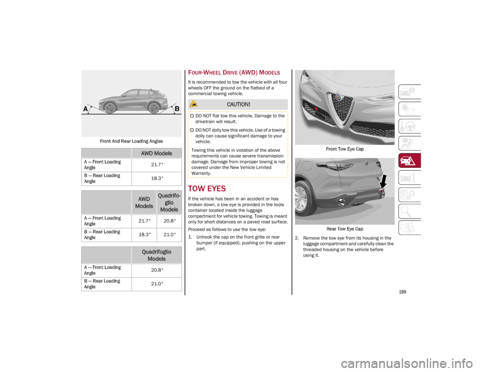
Front And Rear Loading Angles
FOUR-WHEEL DRIVE (AWD) MODELS
It is recommended to tow the vehicle with all four
wheels OFF the ground on the flatbed of a
commercial towing vehicle.
TOW EYES
If the vehicle has been in an accident or has
broken down, a tow eye is provided in the tools
container located inside the luggage
compartment for vehicle towing. Towing is meant
only for short distances on a paved road surface.
Proceed as follows to use the tow eye:
1. Unhook the cap on the front grille or rear bumper (if equipped), pushing on the upper
part. Front Tow Eye Cap
Rear Tow Eye Cap
2. Remove the tow eye from its housing in the luggage compartment and carefully clean the
threaded housing on the vehicle before
using it.
AWD Models
A — Front Loading
Angle 21.7°
B — Rear Loading
Angle 18.3°
AWD
ModelsQuadrifo -
glio
Models
A — Front Loading
Angle 21.7° 20.8°
B — Rear Loading
Angle 18.3° 21.0°
Quadrifoglio
Models
A — Front Loading
Angle 20.8°
B — Rear Loading
Angle 21.0°
CAUTION!
DO NOT flat tow this vehicle. Damage to the
drivetrain will result.
DO NOT dolly tow this vehicle. Use of a towing
dolly can cause significant damage to your
vehicle.
Towing this vehicle in violation of the above
requirements can cause severe transmission
damage. Damage from improper towing is not
covered under the New Vehicle Limited
Warranty.
22_GU_OM_EN_USC_t.book Page 189
Page 195 of 256
193
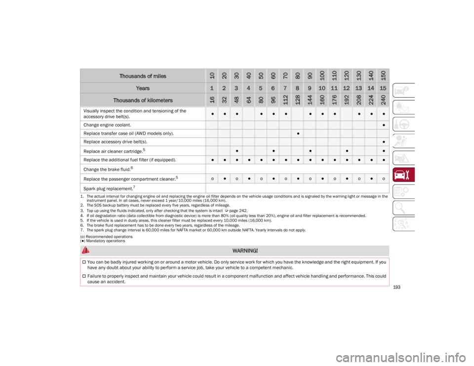
(o) Recommended operations
(●) Mandatory operations
Visually inspect the condition and tensioning of the
accessory drive belt(s).●●●●●●●●●●●●
Change engine coolant.
●
Replace transfer case oil (AWD models only).
●
Replace accessory drive belt(s).●
Replace air cleaner cartridge.
5●●●●●
Replace the additional fuel filter (if equipped).
●●●●●●●●●●●●●●●
Change the brake fluid.
6
Replace the passenger compartment cleaner.5o●o●o●o●o●o●o●o
Spark plug replacement.
7
1. The actual interval for changing engine oil and replacing the engine oil filter depends on the vehicle usage conditions and is signaled by the warning light or message in the instrument panel. In all cases, never exceed 1 year/10,000 miles (16,000 km).
2. The SOS backup battery must be replaced every five years, regardless of mileage.
3. Top up using the fluids indicated, only after checking that the system is intact
Ú
page 242.
4. If oil degradation ratio (data collectible from diagnostic device) is more than 80% (oil quality less than 20%), engine oil and filter replacement is recommended.
5. If the vehicle is used in dusty areas, this cleaner filter must be replaced every 10,000 miles (16,000 km). 6. The brake fluid replacement has to be done every two years, regardless of the mileage.
7. The spark plug change interval is 60,000 miles for NAFTA market or 60,000 km outside NAFTA. Yearly intervals do not apply.
Thousands of miles102030405060708090100110120130140150
Years123456789101112131415
Thousands of kilometers163248648096112128144160176192208224240
WARNING!
You can be badly injured working on or around a motor vehicle. Do only service work for which you have the knowledge and the right equipment. If you
have any doubt about your ability to perform a service job, take your vehicle to a competent mechanic.
Failure to properly inspect and maintain your vehicle could result in a component malfunction and affect vehicle handling and performance. This could
cause an accident.
22_GU_OM_EN_USC_t.book Page 193
Page 197 of 256
195
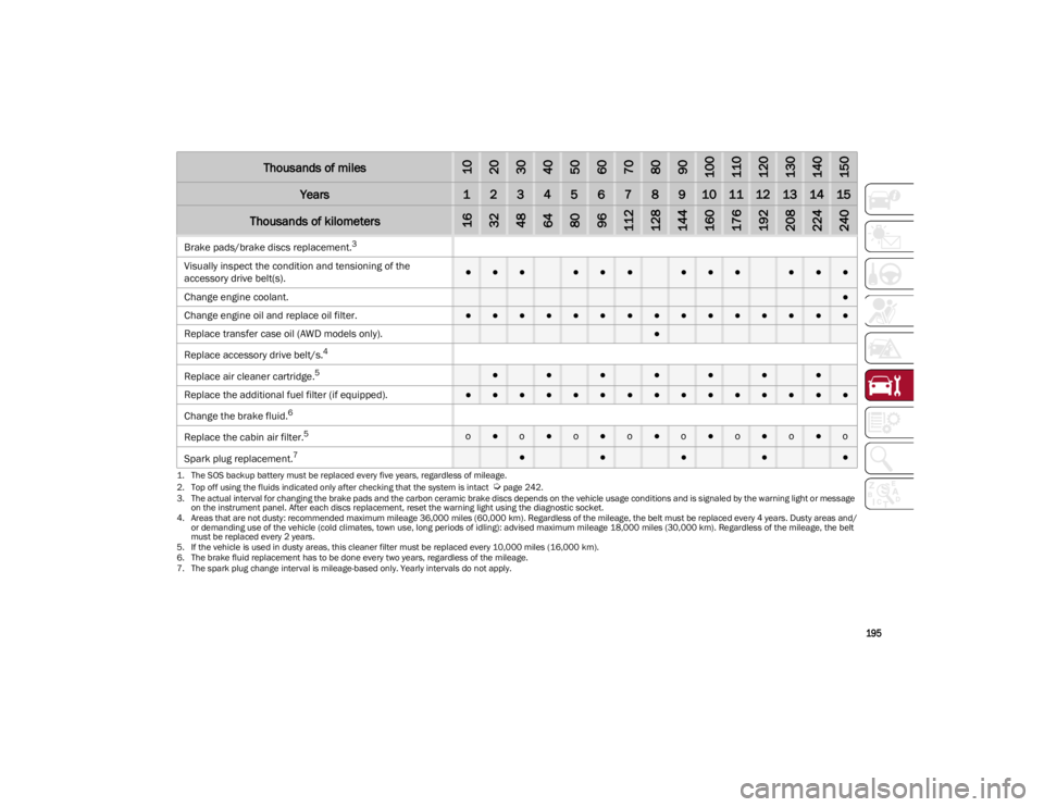
Brake pads/brake discs replacement.
3
Visually inspect the condition and tensioning of the
accessory drive belt(s).●●●●●●●●●●●●
Change engine coolant.
●
Change engine oil and replace oil filter.
●●●●●●●●●●●●●●●
Replace transfer case oil (AWD models only).
●
Replace accessory drive belt/s.4
Replace air cleaner cartridge.5●●●●●●●
Replace the additional fuel filter (if equipped).●●●●●●●●●●●●●●●
Change the brake fluid.
6
Replace the cabin air filter.5o●o●o●o●o●o●o●o
Spark plug replacement.
7●●●●●
1. The SOS backup battery must be replaced every five years, regardless of mileage.
2. Top off using the fluids indicated only after checking that the system is intact
Ú
page 242.
3. The actual interval for changing the brake pads and the carbon ceramic brake discs depends on the vehicle usage conditions and is signaled by the warning light or message on the instrument panel. After each discs replacement, reset the warning light using the diagnostic socket.
4. Areas that are not dusty: recommended maximum mileage 36,000 miles (60,000 km). Regardless of the mileage, the belt must be replaced every 4 years. Dusty areas and/ or demanding use of the vehicle (cold climates, town use, long periods of idling): advised maximum mileage 18,000 miles (30,000 km). Regardless of the mileage, the belt must be replaced every 2 years.
5. If the vehicle is used in dusty areas, this cleaner filter must be replaced every 10,000 miles (16,000 km). 6. The brake fluid replacement has to be done every two years, regardless of the mileage.
7. The spark plug change interval is mileage-based only. Yearly intervals do not apply.
Thousands of miles102030405060708090100110120130140150
Years123456789101112131415
Thousands of kilometers163248648096112128144160176192208224240
22_GU_OM_EN_USC_t.book Page 195