oil ASTON MARTIN DB7 1997 User Guide
[x] Cancel search | Manufacturer: ASTON MARTIN, Model Year: 1997, Model line: DB7, Model: ASTON MARTIN DB7 1997Pages: 421, PDF Size: 9.31 MB
Page 188 of 421
Electrics
Airbag System =7?
Spillage and Leakage
If material is spilled or released, contact Aston
Martin Technical Support for advice on clean-up
procedures. All personnel must be kept away from
the contaminated area.
Do not dispose of contaminated propellant or
water into storm or sanitary sewers, ground water
or
soil.
Spills may be reportable to state and/or federal
authorities.
Materials must be disposed of by incineration or
chemical oxidation under carefully controlled
conditions by specially trained individuals and in
accordancewith local stateandfederal regulations.
Scrapping Vehicles with Live Airbags
when scrapping a vehicle with live airbags, first
deploy the airbags in accordance with the following
procedure. This procedure assumes that the airbag
wiring is undamaged
See Handling/Safety Information.
If the airbags are to be removed, see the airbag
module assembly/removal/servicing instructions.
Equipment required:
Four insulation displacement connectors
(scotch locks).
Charged 'slave' battery.
Two 10 metre lengths of
1
mm^ wire fitted with
crocodile clips on one end.
Procedure
WARNING: The deployment procedure must be
carried out outdoors away from other personnel.
1.
Remove any loose debris from around the airbag
modules and ensure that no flammable liquids are
present.
2.
Disconnect the vehicle battery.
WARNING: Always connect to the airbag
first,
as
the bag will deploy immediately on connection to
the battery.
3. Remove the passenger side airbag deployment
door and underscuttle panel.
4.
Remove the drivers side underscuttle panel.
5. Disconnect the airbag connector for the spiral
cassette under the fascia and at the wire (drivers
side).
6. Locate the harness connectors and cut the wires
leading from the airbag just above the mating plug
(passengers side).
Note: The harness connected between the driver's
airbag
and the connector
has
one red
feed
wire and
one
grey/orange return
wire.
The
harness
connected between
the
passenger's
airbag and the connector
has
one blue/
orange
feed wire and one
pinl
return wire.
6-72 September1996
Page 231 of 421
^"^
Body and Trim
Body Repair
Precautions
Paint
Ensure that there is efficient ventilation at all times. Paint spraying should be confined to spray booths.
Anyone with a history asthma should not be engaged in any process which involves the use of isocyanates.
Any operator working inside a spray booth where isocyanates are present must use air-fed breathing equipment.
Supplied air to the visor should be fed at the recommended pressure and filtered to remove oil, water and fumes.
Operators involved in handling, mixing or spraying should wear protective clothing, gloves and goggles to avoid
skin and eye contact. A Paticle mask or canister typr respirator should be worn when sanding.
Applied heat
When welding, flame cutting or brazing and so on, goggles, a mask or fume extractor and flameproof protective
clothing should be used always.
It is especially important when working with polyurethane compounds to use air-fed breathing equipment.
Ensure that at all times the appropriate fire fighting equipment isavailableand that personnel are trained in its use.
Metal repair
Wear appropriate eye and hand protection when sanding, drilling, cutting, chiselling, flatting or welding. Wear a
face mask or air-fed visor when sanding or flatting either body solder or
fillers.
When a soldering operation has been
completed,
remove swarf from the work area and wash your hands thoroughly.
General Repair Notes
The following precautions should be noted before any work is carried out:
• disconnect the vehicle battery ground
lead,
taking note of the reconnection procedures
• Make sure that you have read and understood the safety related procedures in this section.
Caution:
Electric arc
welding must not
be
used on the
vehicle as the high
voltages produced by
this process
will
cause
irreparable
damage
to the electrical control and
microprocessor
systems.
All trim and electrical components in the locality of the repair must be removed or disconnected prior to panel
removal or replacement.
Welding and Gas Process Special Notes
Resistance spot welding, MIG welding and all gas processes may only be carried out on bare, unpainted or unplated
metal.
The flanges of panels, which are to be welded together, must be clean, corrosion free and treated as
appropriate with either weld-through or inter-weld sealer.
The resistance spot welding equ ipment used in vehicle repair does not always produce
a
weld of
equ
ivalent strength
to that produced in manufacturing. This means that a single row of spot welds should be spaced on a pitch of 19-
25 mm, which will usually result in more spot welds than found in the original factory joint.
Use a resistance spot weld cutter to remove resistance spot welds. Where a new joint is to be MIC welded, cut the
old resistance spot welds from the panel that is to be retained; the resulting holes are then used for plug welding.
Suitable holes may be drilled or punched as follows:
• 8.0 mm for sections up to 1.5 mm thickness
• 10.0 mm for thicker sections.
Always refer to the welding equipment manufacturers diagrams and tables for the relevant procedure.
May 1996 7-3
Page 276 of 421
"^7
Body and Trim
Cleaning of Alcantara Trim
Cleaning of Alcantara Trimmed Roof Lining and Interior Components
Recommendations
1.
Clean the stain immediately.
Clean the stain working from the edge to the centre of the spot to prevent a ring forming.
Delicately remove most of the dirt with a blunt scraper and immediately blot the spot with a clean white cloth.
Once you've identified the type of stain, follow the instructions in the spot removal chart.
Never pour a solvent directly on the spot; instead pour the solvent on a clean cloth.
After you've applied the spot remover, remove it with a dry clean cloth. Afterwards, brush the area against the
material nap.
7. Let the spot dry. Do not sit on a humid part. Afterwards, vacuum the spot with a vacuum cleaner.
Spot Removal Chart
Type of
Stain
Alcohol-Liquors
Beer
Coffee, Tea, Milk
Chocolate, Confectionary
Paints
Cosmetics
Grass, Plants
Chewing Gum
Ink
Marmalade, Syrup, Fruit Juice
Oil,
Grease
Ballpoint Pen
Wine Beverages
Cleaning Product and
Cleaning Method
Wash with mild soap, then blot with denatured alcohol
Blot with lukewarm water (max 50°C) and denatured alcohol at 3%
Washwithmildsoap. If the stain persists, blot with denatured alcohol or ammonia diluted
at 10%.
Blot with lukewarm water (max 50°C) or with ammonia diluted at 5%.
Oil Paint - Blot with ethyl alcohol then wash with mild soap.
Water Based Paint - If the stain is fresh, blot with cold water. An old stain is very difficult
to remove, consult a specialist.
Apply ethyl alcohol or perchloroethylene, then wash with mild soap. If the stain persists,
use ammonia diluted at 5% or denatured alcohol.
Blot with lukewarm water (max 50°C) then wash with mild soap.
Blot with acetone.
Remove as much as possible with a paper towel. Blot with a solution of 30% denatured
alcohol and 70% water, then wash with mild soap. Lemon juice also gives good results.
Blot with lukewarm water (max 50°C). If the stain persists, use ethyl alcohol or
perchloroethylene
Blot with denatured alcohol, then wash with mild soap.
Blot with perchloroethylene and denatured alcohol.
Blot with water and vinegar (50%), then wash with mild soap.
May 1996 7-21
Page 278 of 421
in:!M3^^?
Air Conditioning
Contents
Contents
General Description 8-5
Specifications 8-5
Climate Control System 8-6
System Description 8-7
Special Servicing Tools and Equipment 8-7
Working Practices 8-8
General 8-8
Handling Refrigerant 8-8
Handling Lubricating Oil 8-8
System Maintenance 8-8
Temperature Distribution System 8-9
Fan Speed Control (Mode Switch) 8-10
Face Level Temperature Differential 8-10
Temperature Rotary Control 8-10
Refrigeration Cycle 8-11
System Protection 8-12
General System Procedures 8-12
Leak Test 8-12
Charge Recovery (System Depressurisation) 8-12
Evacuating the System 8-13
Adding Compressor Lubricating Oil 8-13
Adding Refrigerant 8-14
Functional Check 8-15
System Trouble Shooting 8-1 7
Electronic Control Module (ECM) 8-19
In Car Controls 8-21
Temperature Demand Switch 8-21
Face Level Differential Controller 8-21
Air Conditioning Function Switch 8-22
Fan Speed Control Switch (Mode Switch) 8-23
Temperature Sensors 8-23
Evaporator Sensor 8-24
Motorised In-Car Aspirated Sensor 8-24
Water Temperature Switch 8-25
Blower Motors 8-25
Potentiometers 8-26
Servo Motors 8-27
Vacuum System 8-28
Pressure-Temperature Graphs 8-29
May 1996 8-1
Page 279 of 421
Air Conditioning
Contents '=2?
System Fault Diagnosis
Fault Finding
Blower Motor Test
Open Water Temperature Switch Needs
Short Water Temperature Switch Leads
Refrigeration
Compressors
Compressor Clutch Control
Trinary Switch
Condenser
Receiver-Drier
Evaporator
Expansion Valve
Sanden Compressor SD7H15
Manifold Gauge Set
System Checking with the Manifold Gauge Set
Evacuating the Manifold Gauge Set
Connecting the Manifold Gauge Set
Stabilising the System
Purging the Test Hoses
Leak Test
Manifold Gauge Set Check Procedures
Refrigerant Slightly Low.
Refrigerant Excessively Low.
Air In The System.
Compressor Malfunction
Moisture in the System
A Large Amount of Air in the System.
Expansion Valve Malfunction.
Expansion Valve Malfunction
Restriction in the High Pressure Side.
Torque Levels for the Hose Connections
8-30
8-33
8-33
8-33
8-34
8-35
8-35
8-35
8-35
8-36
8-36
8-36
8-37
8-39
8-39
8-39
8-39
8-40
8-40
8-41
8-41
8-42
8-42
8-43
8-44
8-45
8-45
8-46
8-46
8-47
Air Conditioning Procedures
Depressurising
Recovering Refrigerant
Evacuating and Recycling the Refrigerant
Recharging the System
Compressor Oil Check
8-47
8-47
8-48
8-49
8-49
8-2 May 1996
Page 280 of 421
^7
Air Conditioning
Contents
Repair Procedures
8.1.01.1 Compressor Removal/Renewal 8-51
8.1.02.1 Field Coil Renewal 8-52
8.1.03.1 Renew Gasket Kit 8-52
8.1.04.1 Valve Plate Renewal 8-53
8.1.05.1 Expansion Valve Renewal 8-54
8.1.06.1 Hose-Compressor to Evaporator Renewal 8-55
8.2.01.1 Air Conditioning Unit Renewal 8-55
8.2.02.1 Evaporator Unit Renewal 8-56
8.2.03.1 Upper Servo Feedback Potentiometer Renewal 8-57
8.2.04.1 Lower Servo Feedback Potentiometer Renew 8-57
8.2.05.1 Upper Flap Motor Assembly Renew 8-58
8.2.06.1 Lower Flap Motor Assembly Renew 8-58
8.2.07.1 Ambient Temperature Sensor Renew 8-59
8.2.08.1 Blower Motor Driver Side Renewal 8-59
8.2.09.1 Blower Motor Passenger Side Renewal 8-59
8.2.10.1 Blower Assembly Driver/Passenger Side Overhaul 8-60
8.2.11.1 Blower Motor High Speed Relay Renewal 8-61
8.2.12.1 Water Temperature Switch Renewal 8-62
8.2.13.1 Heater Matrix Renewal 8-62
8.2.14.1 Electronic Control Module Renew 8-63
8.3.01.1 Vacuum System Solenoid Renewal 8-63
May 1996 8-3
Page 282 of 421
Em^^^?
Air Conditioning
General Description
General Description
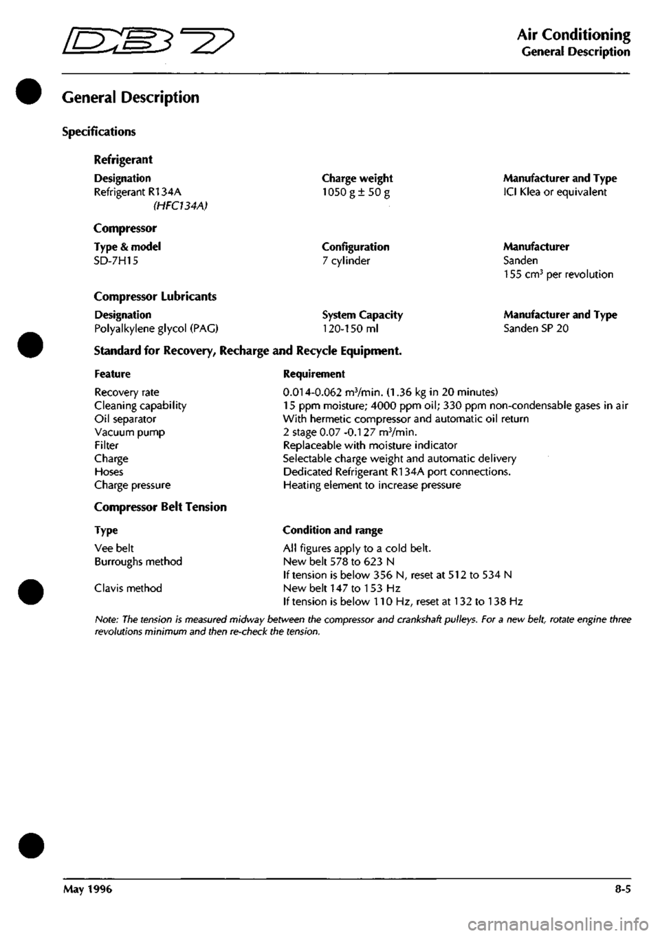
Specifications
Refrigerant
Designation
Refrigerant R134A
(HFCUAA)
Compressor
Type
&
model
SD-7H15
Charge weight
1050g±50g
Configuration
7 cylinder
Compressor Lubricants
Designation
Polyalkylene glycol
(PAG)
Standard
for
Recovery, Recharge
and
Recycle Equipment,
System Capacity
120-150
ml
Manufacturer and Type
ICI Klea
or
equivalent
Manufacturer
Sanden
155 cm^
per
revolution
Manufacturer and Type
Sanden SP
20
Feature
Recovery rate
Cleaning capability
Oil separator
Vacuum pump
Filter
Charge
Hoses
Charge pressure
Compressor Belt Tension
Type
Vee belt
Burroughs method
Clavis method
Requirement
0.014-0.062
mVmin.
(1.36 kg in 20
minutes)
15
ppm
moisture; 4000
ppm oil; 330 ppm
non-condensable gases
in air
With hermetic compressor and automatic
oil
return
2 stage
0.07
-0.127 mVmin.
Replaceable with moisture indicator
Selectable charge weight and automatic delivery
Dedicated Refrigerant R134A port connections.
Heating element
to
increase pressure
Condition and range
All figures apply
to a
cold belt.
New belt
578 to 623 N
If tension
is
below
356 N,
reset
at 512 to 534 N
New belt
147 to 153 Hz
If tension
is
below
110 Hz,
reset
at 132 to 138 Hz
Note:
The
tension
is
measured
midway between the
compressor
and crankshaft pulleys. For a new
belt,
rotate engine three
revolutions minimum and then re-check the tension.
May 1996
8-5
Page 283 of 421
Air Conditioning
General Description 5^^?
climate Control System
Features
Refrigerant R134A (Hydro fluorocarbon), non ozone depletory.
PAG (polyalkylene glycol) synthetic compressor lubricating oil.
Dedicated and improved compressor for Refrigerant R134A.
Quick fit and release self sealing charge and discharge ports.
Triple pressure (Trinary) switch to control the compressor (incorporated into the liquid line).
Clamp retained 'O' ring seals at the expansion valve and evaporator.
All aluminium evaporator matrix and pipe work.
Aluminium receiver-dryer (without sight glass) and HFC dedicated desiccant.
Parallel flow extended height condenser.
Single muffler situated in the suction hose.
Improved electrical system connectors.
Improved system control panel.
System Recognition
Identification Features
Aluminium pipes.
Large diameter, quick release charge and recovery ports.
No sight glass.
8-6 May 1996
Page 285 of 421
Air Conditioning
Working Practices O" 15-^?
Working Practices
General
Be aware of, and comply
with,
all health and safety
requirements.
Before beginning any repair or service procedure,
disconnect the vehicle battery ground connection
and protect the vehicle from dirt or damage.
Work in a well ventilated, clean and tidy area.
Recovery and chargeequipment must comply
with,
or exceed the standard detailed in the General
Description.
Handling Refrigerant
Wear eye protection at all times.
Use gloves, keep skin that may come into contact
with refrigerant covered. If the refrigerant comes
into contactwith youreyesorskin wash the affected
area immediatelyw'ith cool water and seek medical
advice, do not attempt to treat yourself.
Avoid inhaling refrigerant vapour, it wil
your respiratory system.
irritate
Never use high pressure compressed air to flush out
a system. Under certain circumstances a
combination of HFC 134A and compressed air in
the presenceofa source ofcombustion (for instance,
welding or brazing equipment), results in an
explosion that releases toxic compounds into the
atmosphere.
The refrigerant and CFC 12 must never come into
contact with each other
as
they form an inseparable
mixture that can only be disposed of by incineration.
Do not vent refrigerant directly into the atmosphere,
always use approved recovery equipment.
Refrigerant is costly but it can be recycled. Clean
the refrigerant, using the recovery equipment and
reuse it.
Carry out LeakTestsonly with an electronic analyser
dedicated to Refrigerant El 34A.
Do not attemptto guess the amount of refrigerant in
a system, always recover it and recharge with the
correct charge weight. Do not depress the charge or
discharge port valves to check for the presence of
refrigerant.
Handling Lubricating Oil
Avoid breathinglubricantmist,itwillcauseirritation
to your respiratory system.
Always decant fresh oil from a sealed container. Do
not leave oil exposed to the atmosphere for any
reason other than to fill or empty a system; PAG oil
is hygroscopic (it absorbs water) and iscontaminated
rapidly by atmospheric moisture.
Following the recovery cycle do not reuse the oil
when it has been separated from the refrigerant;
dispose of the oil safely.
System Maintenance
Do not leave the system open to the atmosphere. If
a unit or part of the system is left open for more than
five minutes, it is advisable to renew the receiver-
dryer. There is not a safe period in which work is to
be carried out. Always plug pipes and units
immediately after disconnection and only remove
plugs when re-connecting.
If replacement parts are supplied without transit
plugs and seals do not use the parts. Return them to
your supplier.
Diagnostic equipment for pressure, mass and
volumeshouidbecalibrated regularly and certified
by a third party organisation.
Use extreme care when handling and securing
aluminium fittings, always use a backing spanner
and take special care when handlingtheevaporator.
Use only the correct or recommended tools for the
job and apply the manufacturer's torque
specifications.
Keep the working area, all components and tools
clean.
8-8 May 1996
Page 289 of 421
Air Conditioning //~-->> ^/zz:^^ • ^ ^
General Svstem Procedures ' —"^ ^ '^ General System Procedures
From the condenser the liquid passes into the Receiver-Drier which has three functions:
• Storage vessel for varying system refrigerant demands.
• Filter to remove system contaminants.
• Moisture removal via the desiccant.
With the passage through the receiver-drier completed the, still high pressure liquid refrigerant, enters the Expansion
Valve where it is metered through a controlled orifice which has the effect of reducing the pressure and temperature.
The refrigerant, now in a cold atomised state, flows into the Evaporator and cools the air which is passing through
the matrix.
As heat is absorbed by the refrigerant it once again changes state, into a vapour, and returns to the compressor for
the cycle to be repeated (Fig. 5).
There is an automatic safety valve incorporated in the compressor which operates should the system pressure be
in excess of
41
bar. The valve re-seats when the pressure drops below 35 bar.
Note: The division of HIGH and LOW side is simply the
system pressure
differential created by the
compressor
discharge
(pressure),
suction
(inlet)
ports and
the
relative inlet and outlet
ports
of the
expansion
valve.
This
differential is critical to
system
fault
diagnosis
and efficiency checks.
System Protection
The trinary pressure switch, located in the liquid line, cuts electrical power to the compressor clutch if the system
pressure is outside of the range of 2 Bar
(1
st Function) to 27 Bar (2nd Function). The third function is to switch on
the cooling fans when pressure exceeds 20 bar.
General System Procedures
Leak Test
Faults associated with low refrigerant charge weight and low pressure may be caused by leakage. Leaks traced to
mechanical connections may be caused by torque relaxation or joint face contamination. Evidence of oil around
such areas is an indicator of leakage. When checking for non visible leaks use only a dedicated Refrigerant El 34A
electronic analyser and apply the probe all round the joint connection. Should a leak be traced to a joint, check that
the fixing is secured to the correct tightening torque before any other action is taken.
Do not forget to check the compressor shaft seal and evaporator.
Note: Never
use
a dedicated
CFC 12
or
naiced
flame type
analyser.
Charge Recovery (System Depressurisation)
The process of refrigerant recovery depends on the basic characteristics of your chosen recovery-recycle-recharge
equipment, therefore, follow the manufacturers instructions carefully. Remember that compressor oil may be drawn
out of the system by this process, take note of the quantity recovered so that it may be replaced.
CAUTION: Observe all relevant safety requirements.
• Do not vent refrigerant directly to atmosphere and always use approved recovery-recycle-recharge
equipment.
• Wear suitable eye and skin protection.
• Do not mix the refrigerant with CFC 12.
• Take note of the amount of recovered refrigerant, it indica
tes the
state of the
system
and
thus the
magnitude
of any problem.
8-12 May 1996