lumbar support ASTON MARTIN DB7 1997 Workshop Manual
[x] Cancel search | Manufacturer: ASTON MARTIN, Model Year: 1997, Model line: DB7, Model: ASTON MARTIN DB7 1997Pages: 421, PDF Size: 9.31 MB
Page 9 of 421

[Em^^^?
Electrics
Repair Procedures
6.1.01
6.1.02
6.1.03
6.1.04
6.1.05
6.2.01
6.3.01
6.3.02
6.5.01
6.5.02
6.5.03
6.5.04
6.5.05
6.5.06
6.5.07
6.5.08
6.6.01
6.6.02
6.6.03
6.6.04
6.6.05
6.6.06
6.6.07
6.6.08
6.7.01
6.7.02
6.7.03
6.7.04
6.7.05
6.7.06
6.7.07
Headlamp Unit
Headlamp Alignment
Front Indicator/Parking Lamp Unit
Front Fog Lamp Assembly
Side Repeater Lamps
Windscreen Wiper Motor
Alternator
Starter Motor
Steering Wheel and Horn Switches
Column Switches
Ignition Switch
Instrument Panel
Radio
Air Conditioning and Switch Panel
Cruise Control, Window and Gearshift Switches
Seat Control Switch Panels
Front Interior Lamps
Rear Interior Lamps
Front Seat Removal
Front Seat Runner Assembly
Front Seat Rail Motor
Lumbar Support Motor
Seat Recline Motor
Seat Control Unit
Door Edge Lamps
Rear Lamp Cluster
Door Central Locking Motors
Door Window Motor
Door Mirror Assembly
Transmission Control Module - Renew (TCM)
Barometric Pressure Sensor - Renew
6-3
6-3
6-4
6-4
6-4
6-5
6-5
6-6
6-6
6-6
6-7
6-7
6-8
6-8
6-9
6-9
6-10
6-10
6-10
6-11
6-11
6-12
6-12
6-12
6-12
6-13
6-13
6-14
6-15
6-16
6-17
April 1997 6-1
Page 20 of 421

Electrics
Lumbar Support, Recline Motor and Seat Control Unit - Removal Procedures
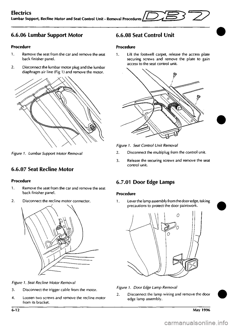
6.6.06 Lumbar Support Motor
Procedure
1.
Remove the seat from the car and remove the seat
back finisher panel.
2.
Disconnect the lumbar motor plug and the lumbar
diaphragm air line (Fig 1) and remove the motor.
Figure /. Lumbar Support Motor Removal
6.6.07 Seat Recline Motor
6.6.08 Seat Control Unit
Procedure
1.
Lift the footwell carpet, release the access plate
securing screws and remove the plate to gain
access to the seat control unit.
Figure 1. Seat Control Unit Removal
2. Disconnect the multiplug from the control unit.
3. Release the securing screws and remove the seat
control unit.
Procedure
1.
Remove the seat from the car and remove the seat
back finisher panel.
2.
Disconnect the recline motor connector.
Figure 1. Seat Recline Motor Removal
3. Disconnect the trigger cable from the motor.
4.
Loosen two screws and remove the recline motor
from its bracket.
6.7.01 Door Edge Lamps
Procedure
1.
Lever the lamp assembly from the door
edge,
taking
precautions to protect the door paintwork.
Figure 1. Door Edge Lamp Removal
2. Disconnect the lamp wiring and remove the door
edge lamp assembly.
6-12 May 1996
Page 111 of 421

Electrics
Component Index Sheet 4-97 MY ^7
Component
Name
Relay - Rear Fog Lamps
Relay - Reverse Lamps
Relay - Right Quarter Light Up
Relay - Right Quarter Light Down
Relay - Sidelights {
Relay - Starter Solenoid
Relay - Stop Lamps
Relay- Tilt Sensor
Reversing Light Switch
Screen Wash Pump
Seat Belt Stalk
Seat Belt Pretensioner Control Module
Seat Belt Pretensioner Squib
Seat ECU - Driver
Seat ECU - Passenger
Seat Fore/Aft Motor Potentiometer
Seat Heater Cushion Element
Seat Heaters - Driver
Seat Heaters - Passenger
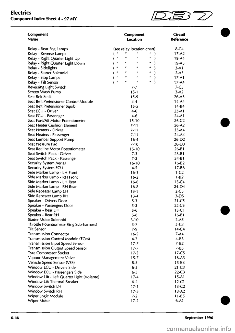
Seat Lumbar Support Pump
Seat Pressure Pad
Seat Recline Motor Potentiometer
Seat Switch Pack - Driver
Seat Switch Pack - Passenger
Security System Aerial
Security System ECU
Side Marker Lamp - LH Front
Side Marker Lamp - RH Front
Side Marker Lamp - LH Rear
Side Marker Lamp - RH Rear
Side Repeater Lamp LH
Side Repeater Lamp RH
Speaker - Drivers Door
Speaker - Passengers Door
Speaker - Rear LH
Speaker - Rear RH
Starter Motor Solenoid
Throttle Potentiometer (Eng Sub-harness)
Tilt Sensor
Transmission Connector
Transmission Control Module (TCM)
Transmission Input Speed Sensor
Transmission Output Speed Sensor
Tyre Compressor Socket
Vapour Management Valve
Vehicle Speed Sensor (VSS)
Window ECU - Drivers Side
Window ECU - Passengers Side
Window Lift - Left Quarter Light (Volante)
Window Lift Thermal Breaker
Window Switch LH
Window Switch RH
Wiper Logic Module
Wiper Motor
6-46
Component
Location
Circuit
Reference
(see relay location chart) 8-C4 it ti It
II H U
tl 11 U
a II 11
II II II
II Ji II
II II II
7-7
15-1
15-9
4-4
15-5
4-6
4-6
15-10
7-11
7-n
7-11
16-4
7-10
15-10
7-3
7-3
16-10
4-5
16-1
16-2
16-6
16-8
13-1
13-4
5-3
5-3
5-6
5-6
3-10
3-7
7-9
16-5
4-7
17-7
17-7
17-5
15-7
8-5
6-3
6-3
17-4
6-4
17-1
17-3
7-2
17-2
' ) 17-A2
' ) 19-A4
' ) 19-A5
' ) 2-A1
' ) 2-A3
' ) 17-A1
' ) 17-A4
7-C5
3-A2
26-A3
14-A4
14-B4
23-A1
24-A1
26-C2
26-A2
23-A4
24-A4
26-D2
26-D3
26-B1
23-B1
24-B1
16-B2
17-B6
1-C2
1-82
15-C4
24-D4
2-C5
3-D5
21-C5
22-C5
15-Cl
16-B1
2-A5
5-C3
14-C4
7-A4
4-B5
7-B2
7-B3
17-C5
16-A3
15-B3
21-C3
22-C3
15-A1
12-Cl
13-C2
13-A2
11-B5
6-A1
September 1996
Page 227 of 421

3-^?
Electrics
Seat Removal/Replacement 97.5 MY
6.6.03
Seat Removal 97.5 MY
Description
The 97.5 MY front seats are common to the DB7
Coupe
and
Volante
models.
Seat
switch
assembi ies
are located on the outboard side of both driver and
passenger
seats.
The front switch controls fore and
aft movement and the seat height adjustment. The
centre switch controls the recline adjustment. The
rear switch
controls
the
lumbar support adjustment.
The seat
heater switches are mounted on the centre
console, forward of the gear selector
lever.
Only one of
the
slide,
recline or height motors can
be driven under manual control at any one time.
Each seat switch pack is hard wired to the relevant
Seat Control
Module
beneath each
seat.
The
module
outputs are hard wired to the seat motors.
Removal
WARNING -
Seat
belt
Pretensioners
(if fitted):
To avoid the possibility
of
personal
injury
caused
by accidental deployment of the seat belt
pretensioner,
disconnect
the
vehicle battery and
wait at
least
10
minutes
for all
voltages
to fully
discharge
before working on the
pretensioner
system.
This covers the possibility
of
the normal
capacitor
discharge
circuits being inoperative and
failing to discharge the detonator capacitor when
instructed
to
do
so.
Procedure
1.
Motortheseatto
its
maximum forward position and
remove the fixings at the rear of the slides.
2.
Motor the seat to its maximum rearward position
and remove the front seat slide fixings.
3. Disconnect the battery
ground
(black)
lead.
Wait at
least 10 minutes for the pretensioner power supply
to fully discharge before working on the seat if a
pretensioner is fitted.
Note: Disconnect the battery within 12 seconds of
switching off the ignition to avoid the alarm siren sounding.
4.
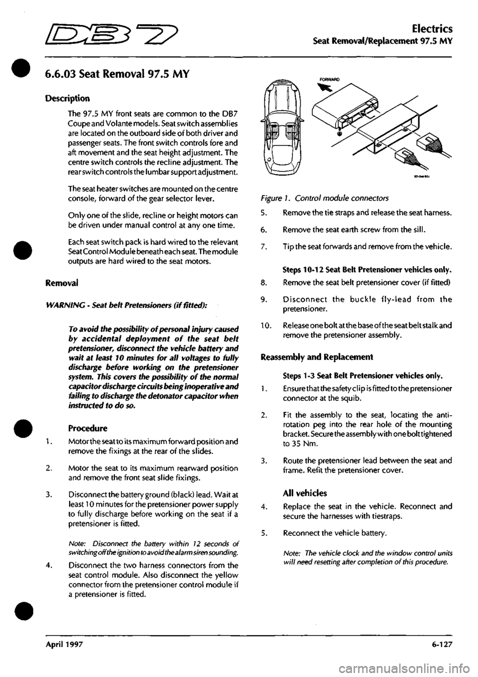
Disconnect the two harness connectors from the
seat control module. Also disconnect the yellow
connector from the pretensioner control module if
a pretensioner is fitted.
Figure 1. Control module connectors
5. Remove the tie straps and release the seat harness.
6. Remove the seat earth screw from the
sill.
7. Tip the seat forwards and remove from the vehicle.
Steps 10-12 Seat Belt Pretensioner vehicles only.
8. Remove the seat belt pretensioner cover (if fitted)
9. Disconnect the buckle fly-lead from the
pretensioner.
10.
Release
one
bolt at
the
base of the
seat
belt stalk and
remove the pretensioner assembly.
Reassembly and Replacement
Steps 1-3 Seat Belt Pretensioner vehicles only.
1.
Ensurethatthesafetyclipisfittedtothepretensioner
connector at the squib.
2.
Fit the assembly to the seat, locating the
anti-
rotation peg into the rear hole of the mounting
bracket.
Securethe
assembly with
one
bolttightened
to 35 Nm.
3. Route the pretensioner lead between the seat and
frame.
Refit the pretensioner
cover.
All vehicles
4.
Replace the seat in the vehicle. Reconnect and
secure the harnesses with tiestraps.
5. Reconnect the vehicle battery.
Note:
The vehicle clock and the window control units
will
need resetting after completion
of
this
procedure.
April 1997 6-127