oil ASTON MARTIN DB7 1997 Owner's Manual
[x] Cancel search | Manufacturer: ASTON MARTIN, Model Year: 1997, Model line: DB7, Model: ASTON MARTIN DB7 1997Pages: 421, PDF Size: 9.31 MB
Page 290 of 421
^2?
Air Conditioning
General System Procedures
Evacuating the System
This process, the removal of unwanted air and moisture, is critical to the correct operation of the air conditioning
system.
The procedures depends on the characteristics of the recovery-recycle-recharge equipment and must be
carried out exactly in accordance with the manufacturers instructions.
Moisture can be highly destructive and may cause internal blockages due to freezing, but more importantly, water
suspended in the PAG oil will damage the compressor. Once the system has been opened for repairs, or the
refrigerant charge recovered, all traces oi moisture must be removed before recharging with new or recycled
refrigerant.
Adding Compressor Lubricating Oil
Oil can be added by three methods, two of which are direct into the system
• via the recovery-recycle-recharge station
• by proprietary oil injector.
Equipment manufacturer's instructions must be adhered to when using direct oil introduction.
The third method may be required because of rectification work to the existing compressor, or the need to fit a new
compressor. From an existing compressor, drain the oil into a measuring cylinder and record the amount. Flush the
unit out with fresh PAG oil and drain thoroughly. Refill the compressor with the same amount of PAG oil that was
drained out originally and plug all orifices immediately ready for refitting to the vehicle. The transit lubricating oil
must be drained and discarded from a new compressor before it may be fitted. An adjustment should be made to
the system oil level by taking into account:
• the quantity found in the original compressor
• the quantity deposited in the recovery equipment oil separator from the charge recovery operation.
Typically, 80 ml can be drained from the original compressor and 30 ml found in the oil separator; the sum of these
volumes (80 + 30 = 110 ml) is the amount of fresh PAG oil that must be put into the new compressor prior to fitting.
Hote:
The
discrepancy
between
this
figure
and
the
nominal capacity of
135
ml is
caused
by normally not
recoverable
oil being
trapped in
components
such
as
the receiver-drier or
evaporator.
The above statements are only true if there is no evidence of a leak. Where a leak has been detected and rectified,
the compressor must be refilled with the specified quantity.
Caution: Always decant
fresh
oil from a sealed container and do not leave oil exposed to the
atmosphere.
PAG oil is very
hygroscopic
(absorbs
water) and rapidly
attracts
atmospheric moisture.
PAG oil must
NEVER
be mixed with mineral
based
oils.
Do not
reuse
oil following a recovery cycle,
dispose
of it
safely.
Depending on the state of the air conditioning system immediately prior to charge recovery and the rate of recovery,
an amount of oil is drawn out with the refrigerant. The quantity is approximately 30 to 40 mi; this may vary, and
the figure is given only for guidance. It is most important that the oil separator vessel in the recovery equipment is
clean and empty at the start of the process so that the amount drawn out may be accurately measured.
May 1996 8-13
Page 291 of 421
Air Conditioning //—->> "^^Izz^^ • ^ ^
General System Procedures L ^—/ ' —^ ^./^
Adding Refrigerant
In order that the air conditioning system may operate efficiently it must contain a full refrigerant charge. The
indications of some system defects, and the results of certain tests, shows that
a
low charge
is
the most probable cause
of the fault. In such cases the charge shou
Id
be recovered from the
system,
the weight noted, and the correct amount
installed.
Note: Never attempt to
guess the
amount of refrigerant in
a
system.
Always recover and
recharge
with
the
correct
charge
weight,
this is the only
accurate
method.
Caution: If oil is drawn out during the recovery
process,
the correct amount can be added directly from your
recovery-recycle-
recharge station
(if so
equipped)
prior to the charging
process.
It must be
stressed
that the need to protect
compressor
oil from
moisture is vital, observe
the procedures
in Handling Lubricating Oil.
Warning: Liquid refrigerant boils at -29°C (-20°F) at atmospheric pressure. Serious injury, even blindness, can occur if
the refrigerant comes into contact with the eyes.
Goggles and gloves must be warn while working with refrigerant.
First Aid
If refrigerant should contact the eyes or
skin,
bathe the eyes or affected area with cold water for several minutes. Do
not rub. As soon as possible thereafter, obtain treatment from a doctor or eye specialist.
8-14 May 1996
Page 294 of 421
^=2?
Air Conditioning
System Trouble Shooting
System Trouble Shooting
There are five basic symptoms associated with air conditioning fault diagnosis. It is very important to identify the area of
concern before starting a rectification procedure. Spend time with your customer on problem identification, and use the
following trouble shooting guide.
The following conditions are not in order of priority.
No Cooling
1.
Is the electrical circuit to the compressor clutch functional?
2.
Is the electrical circuit to the blower motor(s) functional?
3. Slack or broken compressor drive belt.
4.
Compressor partially or completely seized.
5. Compressor shaft seal leak (see 9).
6. Compressor valve or piston damag^ (may be indicated by small variation between HIGH & LOW side pressures
relative to engine speed).
7. Broken refrigerant pipe (causing total loss of refrigerant).
8. Leak in system (causing total loss of refrigerant).
9. Blocked filter in the receiver drier.
10.
Evaporator sensor disconnected?
11.
Dual pressure switch faulty?
Note:
Should a
leak or low
refrigerant be established as
the
cause,
follow
the procedures
for
Recovery-Recycle
-Recharge,
and
observe all refrigerant and oil handling instructions.
insufficient Cooing
1.
Blower motor(s) sluggish.
2.
Restricted blower inlet or outlet passage
3. Blocked or partially restricted condenser matrix or fins.
4.
Blocked or partially restricted evaporator matrix.
5. Blocked or partially restricted filter in the receiver drier.
6. Blocked or partially restricted expansion valve.
7. Partially collapsed flexible pipe.
8. Expansion valve temperature sensor faulty (this sensor is integral with valve and is not serviceable).
9. Excessive moisture in the system.
10.
Air in the system.
11.
Low refrigerant charge.
May 1996 8-17
Page 295 of 421
Air Conditioning
/J=y>f^^^
—p )
System Trouble Shooting
12.
Compressor clutch slipping.
13.
Blower flaps or distribution vents closed or partially seized.
14.
Water valve not closed.
15.
Evaporator sensor detached from evaporator.
Intermittent Cooling
Is the electrical circuit to the compressor clutch consistent?
2.
Is the electrical circuit to the blower motor(s) consistent?
3. Compressor clutch slipping.
4.
Faulty air distribution flap potentiometer or motor.
5. Motorised in-car aspirator or evaporator temperature sensor faulty, causing temperature variations.
6. Blocked or partially restricted evaporator or condenser.
Noisy System
1.
Loose or damaged compressor drive belt.
2.
Loose or damaged compressor mountings.
3. Compressor oil level low, look for evidence of leakage.
4.
Compressor damage caused by low oil level or internal debris.
5. Blower(s) motor(s) noisy.
6. Excessive refrigerant charge, witnessed by vibration and 'thumping' in the high pressure line (may be indicated by
high HIGH & high LOW side pressures).
7. Low refrigerant charge causing 'hissing' at the expansion valve (may be indicated by low HIGH side pressure).
8. Excessive moisture in the system causing expansion valve noise.
Note;
Electrical faults
may
be more rapidly traced using PDU.
Insufficient Heating
1.
Water valve stuck in the closed position.
2.
Motorised in-car aspirator seized.
3. Blend flaps stuck or seized.
4.
Blocked or restricted blower inlet or outlet.
5. Low coolant level.
6. Blower fan speed low.
7. Coolant thermostat faulty or seized open.
8-18 May 1996
Page 311 of 421
Air Conditioning
Refrigeration /s:s^°27
Refrigeration
Safety Precautions
The air conditioning system is designed to use only
Refrigerant E134A (dichlorodifluoromethane). Extreme
care must betaken NOT to use
a
methylchloride refrigerant.
The chemical reaction between methylchloride and the
aluminium parts ofthe compressor results in the formation
ofproductswhich burn spontaneously on exposure toair,
or decompose with violence in the presence of moisture.
The suitable refrigerant is supplied under the following
names.
El 34A KLEA or equivalent
Warning: Take care when handling refrigerant. Serious
damage will occur if it is allowed to come into
contact with the eyes. Always wear with goggles
and gloves when working with refrigerant
First Aid
If refrigerant should come into contact with the
eyes or
skin,
splash the eyes or affected area with
cold water for several minutes. DO NOT RUB. As
soon as possible thereafter, obtain treatment from a
Doctor or an eye specialist.
Good Practice
1.
Protective sealing plugs must be fitted to all
disconnected pipes and units.
2.
Theprotectivesealingpiugsmustremain inposition
on ail replacement components and pipes until
immediately before assembly.
3. Any part arriving for assembly without sealing
plugs in position must be returned to the supplier as
defective.
4.
It is essential that a second backing spanner is
always used when tightening or loosening all joints.
This minimises distortion or strain on components
or connecting hoses.
5. Components must not be lifted by connecting
pipes,
hoses or capillary tubes.
6. Care must be taken not to damage fins on the
condenser or evaporator matrices. Any damage
must be rectified by the use of fin combs.
7. Before assembly oftube and hosejoints, use
a
small
amount of clean new refrigerant oil on the sealing
seat.
8. Refrigerant oil for any purpose must be kept very
clean and capped at all times. This prevents the oil
absorbing moisture.
9. Before assembly the condition of joints and flares
must be examined. Dirt and even minor damage
will cause leaks at the high pressure points
encountered in the system.
10.
Dirty end fitting can only be cleaned using a cloth
wetted with alcohol.
11.
Afterremovingsealingplugsand immediatelybefore
assembly, visually check the bore of pipes and
components. Where any dirt or moisture is
discovered,
the part must be rejected.
12. Ail components must be allowed to reach room
temperature before sealing plugs are removed.
This prevents condensation should the component
be cold initially.
13.
Before finally tightening hose connections ensure
that the hose lies in the correct position, is not
kinked or twisted and will not be trapped by
subsequent operations, e.g., refitting or closing
bonnet.
14.
Check that hoses are correctly fitted in clips or
straps.
15.
The compressor must be stored horizontally with
the sump down. It must not be rotated before fitting
and charging. Do not remove the shipping plate
until immediately before assembly. Always use
new "O" ring seals in those joints that incorporate
them.
"O" ring seals should be coated with
compressor oil before fitting.
16.
Components or hoses removed must be sealed
immediately after removal.
1 7. Afterthe system has been opened the receiver-drier
must be renewed.
18.
Before
testing,
run the engine until normal running
temperature is reached. This ensures that sufficient
vacuum is available for test. For cooling tests the
engine must be running for the compressor clutch
to operate.
8-34 May 1996
Page 312 of 421
'^T?
Air Conditioning
Compressors
Compressors
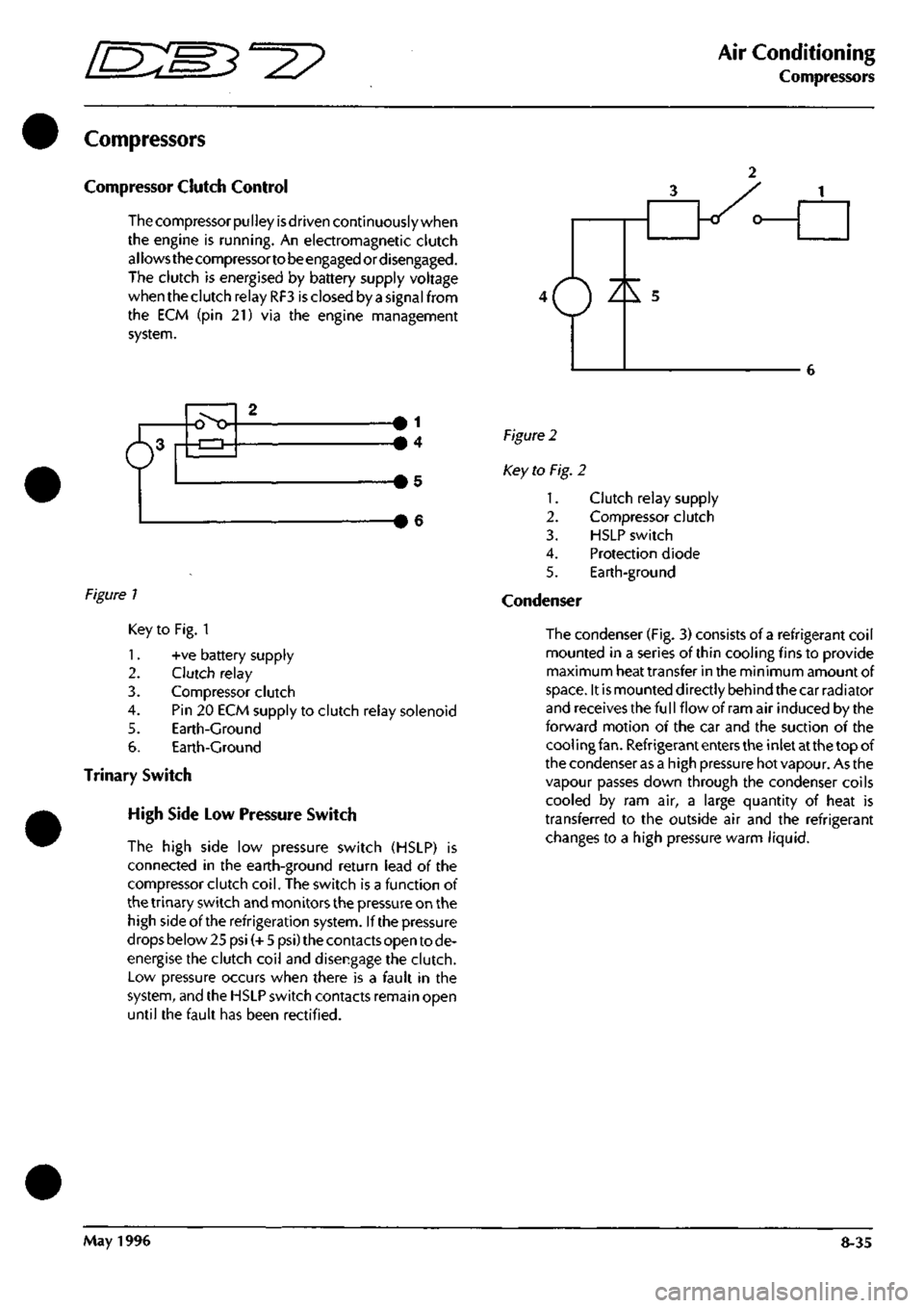
Compressor Clutch Control
The compressor
pu I
ley
is
driven continuously when
the engine is running. An electromagnetic clutch
allows the compressortobeengagedordisengaged.
The clutch is energised by battery supply voltage
when the clutch relay RF3 is closed by a signal from
the ECM (pin 21) via the engine management
system.
6^
o>o 1
4
Figure 1
Figure 2
Key to Fig. 2
1.
2.
3.
4.
5.
Condenser
Clutch relay supply
Compressor clutch
HSLP switch
Protection diode
Earth-ground
Key to Fig. 1
1.
+ve battery supply
2.
Clutch relay
3. Compressor clutch
4.
Pin 20 ECM supply to clutch relay solenoid
5. Earth-Ground
6. Earth-Ground
Trinary Switch
High Side Low Pressure Switch
The high side low pressure switch (HSLP) is
connected in the earth-ground return lead of the
compressor clutch
coil.
The switch is a function of
the trinary switch and monitors the pressure on the
high side of the refrigeration system. If the pressure
drops below 25 psi (+ 5 psi) the contacts open to de-
energise the clutch coil and disengage the clutch.
Low pressure occurs when there is a fault in the
system,
and the HSLP switch contacts remain open
until the fault has been rectified.
The condenser (Fig, 3) consists of a refrigerant coil
mounted in a series of thin cooling fins to provide
maximum heat transfer in the minimum amount of
space.
It is mounted directly behind the car radiator
and receives the fu
11
flow of ram air induced by the
forward motion of the car and the suction of the
cool ing
fan.
Refrigerant enters the inlet at the top of
the condenser as a high pressure hot vapour. As the
vapour passes down through the condenser coils
cooled by ram air, a large quantity of heat is
transferred to the outside air and the refrigerant
changes to a high pressure warm liquid.
May 1996 8-35
Page 313 of 421
Air Conditioning
Compressors ^?
Evaporator
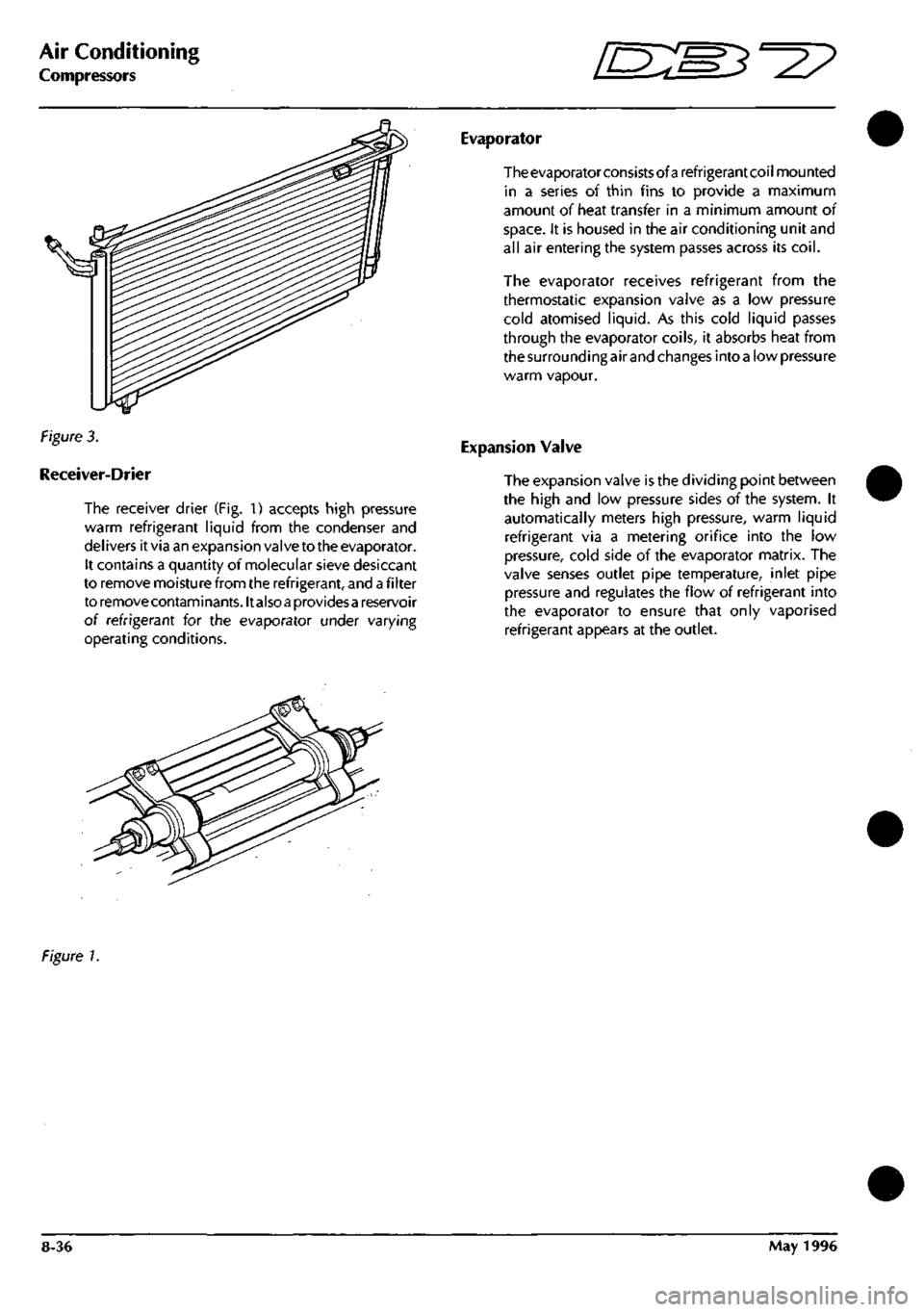
Figure 3.
Receiver-Drier
The receiver drier (Fig. 1) accepts high pressure
warm refrigerant liquid from the condenser and
del ivers it via an expansion valve to the evaporator.
It contains a quantity of molecular sieve desiccant
to remove moisture from the refrigerant, and
a
fi Iter
to removecontaminants.lt also
a
providesa reservoir
of refrigerant for the evaporator under varying
operating conditions.
The evaporator consists of a refrigerant coil mounted
in a series of thin fins to provide a maximum
amount of heat transfer in a minimum amount of
space.
It is housed in the air conditioning unit and
all air entering the system passes across its
coil.
The evaporator receives refrigerant from the
thermostatic expansion valve as a low pressure
cold atomised liquid. As this cold liquid passes
through the evaporator coils, it absorbs heat from
the surrounding air and changes into
a
low pressure
warm vapour.
Expansion Valve
The expansion valve is the dividing point between
the high and low pressure sides of the system. It
automatically meters high pressure, warm liquid
refrigerant via a metering orifice into the low
pressure, cold side of the evaporator matrix. The
valve senses outlet pipe temperature, inlet pipe
pressure and regulates the flow of refrigerant into
the evaporator to ensure that only vaporised
refrigerant appears at the outlet.
Figure 1.
8-36 May 1996
Page 314 of 421
^?
Air Conditioning
Sanden Compressor SD7H15
Sanden Compressor SD7H15
The Sanden SD7H15 compressor
is a 7
cylinder
machine with
a
bore
of
29.3
mm (1.15 in) and a
stroke
of
32.8
mm (1.29
inches).
The displacement
per
revolution
is
155cc
(9.5
cubic inches).
The magnetic clutch
is
engineered with
the
compressor
as a
complete assembly resulting
in a
relatively small unit
of
lightweight construction.
The compressor may be mounted up to 90° from
its
upright position.
The compressor incorporates
a
lubrication system
which reduces the
oil
circulation ratio
to a
level
of
less than
2% at 1800 rpm.
An
oil
deflector
and
positive pressure differential
lubrication system promotes oiling
to the
cylinder
wall,
piston
rod
assemblies, main bearings
and
shaft
seal,
and
ensures that
oil
circulation
to the
refrigeration circuit
is
kept
to a
minimum.
The
compressor ischarged
with!
35 cc(4.6fluid ounces)
ofSunico NoSGSoil at the factory. Only this oil
or
oneoftheequivalentoilsdetailed below should
be
used.
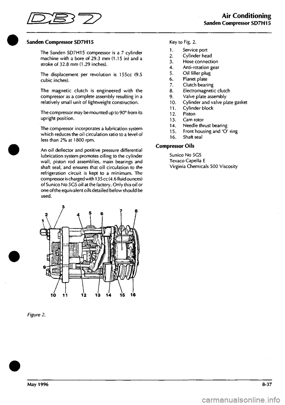
Key
1.
2.
3.
4.
5.
6.
7.
8.
9.
10.
11.
12.
13.
14.
15.
16.
to Fig. 2.
Service port
Cylinder head
Hose connection
Anti-rotation gear
Oil filler plug
Planet plate
Clutch bearing
Electromagnetic clutch
Valve plate assembly
Cylinder and valve plate gasket
Cylinder block
Piston
Cam rotor
Needle thrust bearing
Front housing and 'O' ring
Shaft seal
Compressor Oils
Suni
CO
No 5GS
Texaco Capella E
Virginia Chemicals 500 Viscosity
13
14 15 16
Figure
2.
May
1996
8-37
Page 317 of 421
Air Conditioning
System Checking with the Manifold Gauge Set D'^?
Purging the Test Hoses
1.
With the manifold test set attached to the system.
2.
Purge the high pressure test hose by cracking open
the high pressure side hand valve on the manifold
gauge set for 3 to 5 seconds. This allows the system
refrigerant to purge the air from the test hose and
discharge through the manifold centre test hose.
Immediately cl ose the high pressure side hand
valve.
3. Purge the low pressure test hose in the same manner
by cracking open the low pressure side hand valve
manifold gauge
set
for 3 to 5 seconds, then close the
hand valve.
Stabilising the System
The manifold gauge set is now attached to the
system and the test hoses purged of air. With both
hand valves closed, the system must be operated
for a few minutes to stabilise all pressures and
temperatures throughout the system in order to
obtain accurate test gauge readings.
Proceed as follows:
1.
Place all test hoses, gauge set and other equipment
away from all engine moving parts. Also keep the
hoses from touching the hot engine manifold.
2.
Start the engine and adjust engine speed to fast idle
3. Turn on the air conditioning and set for maximum
cooling with blower fans on high speed
4.
Open the car doors and/or windows (to quickly
eliminate car interior heat).
5. Operate the system under these conditions for 5 to
10 minutes to stabilise the system ready for testing.
6. Check the system for full refrigerant by noting the
sightglass indications. Some refrigerant loss occurs
over a period of time.
Note: The air conditioning
system
must contain a full
refrigerant
charge
before an accurate
system
check can
be
made.
An insufficient
charge
is indicated by
a stream
of
bubbles
or
foam.
If
the
refrigerant charge is low, the
system
must
be
fullydischarged into
a
refrigerant recovery
station and recharged with the correct weight of refrigerant
82.30.08. Do not top up a
system
with refrigerant.
Leak Test
A high proportion of ail air conditioning work
consists of locating and repairing leaks.
Many leaks are located at connections and are
caused by vibration. They may only require the re-
tightening of a connection or clamp.
Occasionally a hose rubs on a structural part of the
vehicle and creates a leak, or a hose deteriorates
which will require a replacement.
The specified maximum leakage rate at each fitting
is 0.5 kg of R 134a in 40 years and a leak detector
capable of operating to this accuracy must be
provided.
To check place the leak detector probe at
the lowest pointofeach joint, pausefortwo seconds.
Do not wave the probe about as refrigerant is
heavier than air and flows to the lowest point. If a
leak is greater than 0-5 kg in forty years is detected
identify the leak point for rectification.
Check that the leaking fitting has been tightened to
the correct torque. If the torque is low, rectify and
repeat leak test. If the torque is satisfactory,
depressurise the system, dismantle the leaking
connection and check the quality of the fitting.
If the fitting is satisfactory, clean and reassemble
after applying a thin film of refrigerant to the seat of
aflarefitting, ora newoiled "O" ring to an "O" ring
fitting.
Tighten to the correct torque.
Charge the system with 200 g of El 34A and leak test
the rectified system. If the system is satisfactory,
depressurise, evacuate and recharge the system.
If the system is unsatisfactory, i.e. leakage greater
than 0.5 kg in forty years, depressurise and replace
the leaking assembly.
8-40 May 1996
Page 318 of 421
=2?
Air Conditioning
System Checking with the Manifold Gauge Set
Pressure Temperature Relationship.
Note:
Pressures
shown are under exact conditions
(see
test
conditions) and
are
not
necessary
true for every
car
checked.
Ambient Temperature is given as the air
surrounding the
condenser
and
is
taken 5 cm in front of
the
condenser.
Test Conditions.
Use a large fan to substitute for normal ram air through the
condenser. Engine adjusted to fast idle speed.
All conditions equivalent to 30 m.p.h. or 48 km/h.
Ambient
Evaporator
Temp °C
16
18
21
24
27
29
32
35
38
41
43
46
49
High
Pressure
Gauge
Reading
Ibf/in2
95-115
105-125
115-125
130-150
1
50-170
165-185
175-195
185-205
210-230
230-250
250-270
265-285
280-310
Low
Pressure
Gauge
Reading
Ibf/in2
10
12
4
16
18
20
22
24
26
28
30
35
40
45
50
55
60
65
70
Ten
-16
-14
-12
-10
-8
-6
-5
-4
-3
-1
0
2
5
9
11
14
17
19
21
Normal operating ambient temperature range is:
-24 to 43°C.
Normal operating evaporator temperature range
is:-12toO°C.
Under normal running conditions system pressure
should be, as follows:
Lowside:1.05to2.10kgf/cm21.034to2.06bar15
to 30 ibf/in2
High side: 13.00 to 14.40 kgf/cm2 12.75 to 14.34
bar185to205lbf/in2
Manifold Gauge Set Check Procedures
Refrigerant Slightly Low.
Complaint.
Little or no cooling.
1.
2.
3.
4.
1.
2.
3.
4.
5.
6.
7.
BLUE LOW SIDE
KED
HIGH SIDE
Condition.
The low side gauge reading is too low.
The high side gauge reading is too low.
A stream of bubbles evident in the sight glass.
The discharge air from the evaporator only
slightly
cool.
Diagnosis.
The system low on refrigerant due to slight leak.
Correction.
Test the system for leaks.
Depressurise the system.
Repair the leaks, and if necessary renew hoses or
units.
Check the compressor oil level. The system may
have lost oil due to leakage.
Evacuate the system using a vacuum pump.
Recharge the system with new refrigerant.
Operate the system and check the performance.
May 1996 8-41