steering ASTON MARTIN DB7 1997 User Guide
[x] Cancel search | Manufacturer: ASTON MARTIN, Model Year: 1997, Model line: DB7, Model: ASTON MARTIN DB7 1997Pages: 421, PDF Size: 9.31 MB
Page 204 of 421
Electrics
Airbag System [D:B3-2?
Airbag DM Fault Code 22
Safing sensor output circuit shorted to battery
voltage.
Normal Operation
The diagnostic module measures the voltage at pin
2-5 (airbag module feed) and 2-5 (safing sensor
output monitor) at thediagnosticmoduleconnector.
The voltage at these pins is dependant on charging
system voltage as shown in the table below. If the
voltage at either pin exceeds 5 volts,
a
fault code 22
will be generated.
in 2-5
2.3V
2.4V
2.5V
2.7V
2.8V
3.0V
3.1V
3.2V
3.4 V
3.5V
3.7V
3.8V
4.0V
4.1V
4.3V
Pin 2-6
2.3V
2.4V
2.5V
2.7V
2.8V
3.0V
3.1V
3.2 V
3.4 V
3.5V
3.7V
3.8V
4.0V
4.1V
4.3V
Charge Volts
9.0V
9.5V
10.0V
10.5V
11.0V
11.5V
12.0V
12.5V
13.0V
13.5V
14.0V
14.5V
15.0V
15.5V
16.0V
Possible Causes
• A short between pins 2-5 or 2-6 and another
wire.
(The wiring to the safing sensor carries
voltages above 5 volts).
• A short between the cable reel cassette circuit
and other 12 volt circu its at the steering column
head.
• A short across the normal ly open contacts of the
safmg sensor.
• Vehiclechargingsystem voltage too
high.
If the
generator output is greater than 17V, fault code
22 may be logged.
Fault Analysis
WARNING: Read and adhere to all warnings and
safety procedures at the start of this section when
working on the airbag system.
Disarm the airbag system and fit airbag simulators
(6.4.21.4).
Check the voltage at the battery with the engine
running at approximately 1500 rpm.
If the voltage is 14.8 ±0.5 volts, the charging
voltage is within specification, go to step 3.
If the voltage is significantly above 14.8 volts (the
voltage regulator set point) service the charging
system.
Clear the code 22. Rearm the airbags
(6.4.21.4)
Check in the area of the diagnostic module
connector for harness damage which could cause
a short circu it to 12 volts. (Note: The airbag system
harness runs are sheathed in black plastic protection
and harness damage is unlikely.)
If no harness damage is evident, go to step 4.
If harness damage is identified, service the wiring as
necessary. Clear the code 22. Rearm the airbags
(6.4.21.4).
Switch on the ignition. Monitor the voltage at pins
2-5 and 2-6 whilst rotatingthe steering from lock to
lock in both directions.
If the voltage at both pins remains below 5.0 volts,
go to step 5.
If the voltage rises to above 5.0 volts, service the
cable reel cassette or wiring as necessary. Clear the
code 22. Rearm the airbags (6.4.21.4).
With the ignition on, check the voltage at pins 2-5
and 2-6 whilst manipulating the bulkhead and
safing sensor harnesses.
If the voltage rises above 5.0 volts, service the
wiring fault in the harness area being manipulated
at the time the voltage rise occurred.
If no voltage rise occurs, fit a new safing sensor as
the most likely cause of the code 22. Clear the code
22 and rearm the airbags (6.4.21.4).
6-88 September 1996
Page 209 of 421

in:m3'^?
Electrics
Airbag System
Airbag DM Fault Code 34
Drivers airbag circuit low resistance or short circuit.
Normal Operation
The diagnostic module measures the resistance
across pins 2-5 and 2-4 every time the ignition is
switched on. The resistance should be 1.6 to 1.8Q.
This value is made up of the airbag
1
.OQ and the
cable reel cassette windings 0.3-0.4£2 per winding.
If the total resistance in the passengers airbag
circuit falls below 0.7Q, fault code 34 will be
declared and the airbag lamp will be illuminated.
Note: The nominal
resistance
of the airbag simulator is
2.5Q, therefore expect
a
total circuit resistance readingof
3.1 -
3.3£2
with the simulator
fitted.
Caution: The drivers airbag connector contains
shorting bars which short circuit pins 1 and 3 of
both sides of the connector when disconnected.
DO NOT REMOVE THE AIRBAC CONNECTOR
SHORTING BAR UNDER ANY CIRCUMSTANCES.
The airbag harness shorting bar may be temporarily
disabled during the following resistance checks.
Possible Causes
• Poorly mated cable reel cassette connector. If
the connector is poorly mated, the shorting bars
may not be fully retracted.
• Faulty shorting bar may short circuit 2-4 and 2-
5 together.
• Short circuit in the cable reel cassette windings.
• A short across the airbag terminals in the airbag
module.
Fault Analysis
Disarm the airbag system and fit airbag simulators
(6.4.21.4).
Disconnect the diagnostic module and remove the
plastic wedge from connector 2 (black). Measure
the resistance between pins 2-5 and 2-4. The
resistance should be 3.1 - 3.3Q.
If the resistance is 3.1 to 3.3Q, go to step 4.
If the resistance is below 3.1 - 3.3Q, go to step 3.
Disconnect the cable reel cassette connector at the
steering column and remove the plastic wedge.
Measure the resistance from pins 2-4 and 2-5 at the
diagnostic module connector.
If the resistance is infinity, check the cable reel
cassette for short circuits. Replace the column
switchgear assembly if necessary. Refit the plastic
wedges. Reconnect the diagnostic module. Clear
the code 34. Rearm the airbags (6.4.21.4).
If the resistance is less than infinity, replace the
main airbag harness. Refit the plastic wedges.
Reconnect the diagnostic module. Clear the code
34.
Rearm the airbags (6.4.21.4).
Since the circuit resistance is in specification, the
fault must lie in the diagnostic module or in the
airbag module.
Substitute a known good diagnostic module. If
code 34 recurs with the airbag simulator fitted,
there is still a fault in the wiring or the simulator.
If the fault code 34 does not recur, rearm the airbags
(6.4.21.4) and retest.
If fault code 34 recurs with the airbag modulefitted,
the airbag module is faulty. Replace the drivers
airbag module (4.5.01.3).
September 1996 6-93
Page 218 of 421
Electrics //—>> ^^^^^^ • >^
Seat Belt Pretensioner I'•—
-"i-t.
^-^
JH—X
System Fault Strategy
No single fault may cause an unexpected deployment. The controller will supervise the pretensioner electrical
system in order to warn the driver should a fault occur. Any fault detected by the self diagnostics shall cause the SRS/
airbag warning lamp to be activated, and in some cases the pretensioner control module to enter shutdown mode.
In shutdown mode, the energy of the reserve capacitors shall be discharged to avoid unintended deployment.
As the ignition is switched on, the pretensioner controller will directly discharge the energy capacitors. When the
start up procedure is completed without detecting any faults, the DC/DC converter will be activated allowing the
capacitors to be charged. The system shall be fully active within
11
secondsafterswitchingthe ignition on providing
that no faults are detected.
All system faults monitored by the controller are filtered in software to avoid fault warnings due to transient electrical
disturbances.
If a fault which could lead to inadvertent deployment is detected by the microprocessor, a software shutdown will
be generated. However, a leakage to an earth or positive potential in the pretensioner output circuit shall not cause
the controller to enter shutdown mode.
If a permanent short of the ignition transistor occurs, a shutdown shall be generated by the hardware circuit. If a
shutdown occurs, the system shall be unable to deploy the pretensioner after a period of 3 seconds (i.e. capacitors
discharged to under minimum deployment voltage).
WARNING: To avoid the possibility of personal injury caused by accidental deployment of the pretensioner,
disconnect the vehicle battery and wait at least 10 minutes for all voltages to fully discharge before working on
the pretensioner
system.
This
covers the possibility of the normal capacitor discharge circuits being inoperative
and failing to discharge the capacitor when instructed to do so.
WA RNING: Do not make any electrical measurements on the pretensioner squib. Electrical measurement devices
can induce sufficient voltage to cause unintentional firing of the pretensioner assembly
If the module enters shutdown mode, all diagnostic functions are stopped, but the communications link remains
active.
A fault code corresponding to the cause of the problem may be read by the PDU.
Assembly/Removal/Service I nstructions
WARNING: In the event of a vehicle impact where the airbags and the seatbelt pretensioner (if fitted) are
deployed, the following actions MUST be performed:
Check the condition of the
seatbelts,
steering wheel, steering column, all connections to airbags, and the column
switchgear connectors for integrity and damage. If in any doubt, replace suspected parts for new parts.
Replace both crash
sensors,
the safing sensor and the seatbelt pretensioner module (if fitted).
On completion of all repair procedures, switch on the ignition and check that the Airbag/SRS warning light
comes
on when the ignition is switched on and extinguishes after approximately six seconds indicating satisfactory
completion of the airbag and pretensioner
system
self
tests.
Vehicles for the North American, Australian and Japanese markets are fitted with drivers seat belt pretensioner
systems and are fitted with a shorting plug in the yellow connector adjacent to the pretensioner control module.
Vehicles for other markets do not have drivers seat belt pretensioners fitted but have a blanking plug in the yellow
connector adjacent to the pretensioner control module.
6-102 September 1996
Page 229 of 421
O" D^?
Body and Trim
Contents
Contents
Body and Trim
Body Repair
Potential Risks
Precautions
General Repair Notes
Steel Body Parts - Repair, Remove and Replace
RTM Body Parts
Body Panel and Trim Removal
Front Apron
Front Undertray
Wheel Arch Liners
Side Sills (top fixings)
Side Sills (bottom fixings)
Rear Bumper
Doors
Door Liners
Door Liner (components)
Steering Wheel
Column Switches
Instrument Panel (surround)
Instrument Panel
Facia Underscuttles
Glove Box
Facia Mountings (1)
Facia Mountings (2)
Console Instruments
Radio
Front Seats
Ashtray
Centre Console
Seat ECU Covers
Rear Console
Rear Seats and C Post Trim
Quarter Panels, B Post Panels, Parcel Shelf
Headlining
Roof System Description and Repair Procedures
Vol ante Roof
Roof and Rear Quarter Light Control
Roof Component Location
Roof Control System
9.0.02.1
Roof Removal/Replacement
9.0.02.3
Roof Hydrailic Control System
9.0.02.5
Bleeding the Roof Hydraulic System
9.1.01.1
Rear Quarter Window Renewal
9.1.01.2
Rear Quarter Glass Adjustment
9.1.01.4
Rear Quarter Window Lift Motor - LH
9.1.01.5
Rear Quarter Window Lift Motor - RH
Roof Sealing and Wind Noise
9.2.01.5
'A' Post/Header Sealing and Lock Adj
9.2.01.6
Roof Seals - Adjustment
9.2.01.7
Cheater Plate Seals - Adjust/Renew
9.2.01.8
Door Glass Adjustment
Alcantara Cleaning
7-1
7-2
7-2
7-3
7-3
7-4
7-5
7-6
Sheet 1
Sheet 2
Sheet 3
Sheet 4
Sheet 5
Sheet 6
Sheet 7
Sheet 8
Sheet 9
Sheet 10
Sheet 11
Sheet 12
Sheet 13
Sheet 14
Sheet 15
Sheet 16
Sheet 17
Sheet 18
Sheet 19
Sheet 20
Sheet 21
Sheet 22
Sheet 23
Sheet 24
Sheet 25
Sheet 26
Sheet 27
7-7
7-7
7-8
7-9
7-10
7-11
7-12
7-13
7-14
7-15
7-16
7-17
7-17
7-18
7-19
7-20
7-21
May 1996 7-1
Page 230 of 421
Body and Trim //-->> ^izz^^ ' ^ ^
Body Repair ' —^^ '-^ >^-/
Body Repair
Introduction
This section contains information for the body repair and rectification of the vehicle. Wherever possible the vehicle
must be returned to its original manufactured condition. Following repair the vehicle must be fully checked and, if
necessary, the braking system and steering must be fully reset.
Health and Safety
Ensure that the correct working practices are established before beginning work.
Observe that the correct working practices are followed whether they be legislative or common sense.
Be aware of the potential risks of using materials used in the manufacture and repair of vehicles and take the
appropriate precautions.
Warning: Make sure that the working practices for the air conditioning
system
are followed: do not vent the refrigerant
directly into the atmosphere and always use the approved recovery/recycle /recharge equipment, always wear
suitable protective garments to prevent injury to the eyes and the skin.
Potential Risks
Paint
If the organic solvents, contained in paints, are inhaled for any length of time damage can be caused to the liver,
kidneys, respiratory tract and the digestive system.
Prolonged exposure to isocyanates can cause lung sensitisation and asthma-like symtoms can develop with
subsequent re-exposure to even low concentrations.
Solvent inhilation can cause dizziness or loss of consciousness.
Inhilation of spray dust and sanding debris can cause lung damage.
Paint activatorsand additives will damage the eyesor can cause dermatitis if allowed to splash and come into contact
with these areas. Peroxide and acid catalysts can cause burns.
Applied heat
There is considerable risk of damage to the eyes and skin when welding or flame cutting.
Fire is a serious danger as many materials and fluids in the vehicle are inflammable.
Toxic and dangerous fumes can be liberated when the following are subjected to heat; expanded foam, corrosion
protection,
adhesive and sealing compounds,
trim,
seat material and paints that contain isocyanates.
When heated to
a
temperature of 300°C, polyu rethane based compounds can
1
iberate small quantities of isocyanate.
Many types of nitrogen containing chemicals may be liberated as breakdown products, these chemicals can
contain isocyanates, oxides of nitrogen and hydrogen cyanide.
Potentially toxic or asphyxiant fumes and gases are produced by welding, for example; zinc oxide with zinc coated
panels and ozone gas from the MIC process.
Metal repair
There is considerable risk of damage to the eyes, ears and skin when metal cutting, forming and dressing is being
carried out.
Soldering may be hazardous because of heat generated fumes and skin contact with the materials.
7-2 May 1996
Page 234 of 421
Body and Trim
Body Panel and Trim Removal 5^7
Body Panel and Trim Removal
The following diagrams show the fixings for all
removeable body and trim panels.
Sheet 1. Front Apron
Sheet 2. Front Undertray
Sheet 3. Wheel Arch Liners
Sheet 4. Side Sills (top fixings)
Sheets. Side Sills (bottom fixings)
Sheet 6. Rear Bumper
Sheet 7. Doors
Sheet 8. Door Liners
Sheet 9. Door Liner (components)
Sheet 10. Steering Wheel
Sheet 11. Column Switches
Sheet 12. Instrument Panel (surround)
Sheet 13. Instrument Panel
Sheet 14. Facia Underscuttles
Sheet 15. Glove Box
Sheet 16. Facia Mountings (1)
Sheet
1
7. Facia Mountings (2)
Sheet 18. Console Instruments
Sheet 19. Radio
Sheet 20. Front Seats
Sheet
21.
Ashtray
Sheet 22. Centre Console
Sheet 23. Seat ECU Covers
Sheet 24. Rear Console
Sheet 25. Rear Seats and C Post Trim
Sheet 26. Quarter Panels, B Post Panels, Parcel Shelf
Sheet 27. Headlining
7-6 May 1996
Page 332 of 421
^2?
Air Conditioning Repair Procedures
Hose - Compressor to Evaporator/Air-Con Unit Renew
8.1.06.1 Hose-Compressor
to
Evaporator
Renewal
Procedure
1.
Open the bonnet and fit a wing cover.
2.
Depressurise the air conditioning systenn.
3. Remove the hose to evaporator valve clamping
plate,
disconnect the hose from the valve, remove
and discard the 'O' ring
seal.
4.
Fit a blanking plug to the evaporator valve. Release
the evaporator hose securing clips.
5. Remove the compressor outlet port retaining bolt.
6. Disconnect the hose from the compressor, discard
the hose complete with 'O' ring seals.
7. Connect the hose to the evaporator valve and
tighten clamp onto the hose.
8. Route the hose to the compressor, fit a new 'O' ring
seal and connect it to the compressor.
9. Position the outlet port retaining plate on the
compressor, fit and tighten the securing bolt.
10.
Refit the hose to the clips.
11.
Charge the air conditioning system.
12.
Remove the wing cover and close the bonnet.
8.2.01.1 Air Conditioning Unit Renewal
1.
Disconnect the battery earth
lead.
2.
Drain the engine coolant into a suitable container.
3. Depressurise the air conditioning system.
4.
Disconnect the high and low pressure hoses and
expansion valve from the air conditioning unit (see
expansion valve renewal).
5. Slacken the coolant hose to the heater matrix pipe
securing clips and disconnect the hoses from the
matrix. (This will require the removal of the air
intake hose for access.)
6. Remove the following items from inside the car:
front seats
underscuttle panels/knee bolsters
glove box assembly
facia trim (walnut trim)
radio and ashtray
centre console switch panel assembly
instrument panel and surround trim
steering wheel and column
facia assembly complete
hoses - distribution box to door vents
facia support frame
Details and drawings of the above operations can
be found in the electrical and trim sections.
Disconnect the vacuum hoses from the blower
motors, water valve and reservoir.
Un-clip the electrical harness from the air
conditioningunit, release theelectrical connections
and reposition the harness to allow removal of the
unit.
Displace and remove the footwell ventilator ducts
and hoses (Fig. 1-1).
May 1996 8-55
Page 336 of 421
'nzm^=2?
Air Conditioning Repair Procedures
Blower Motor Renewal
8.2.07.1 Ambient Temperature Sensor
Renew
?\gure
1.
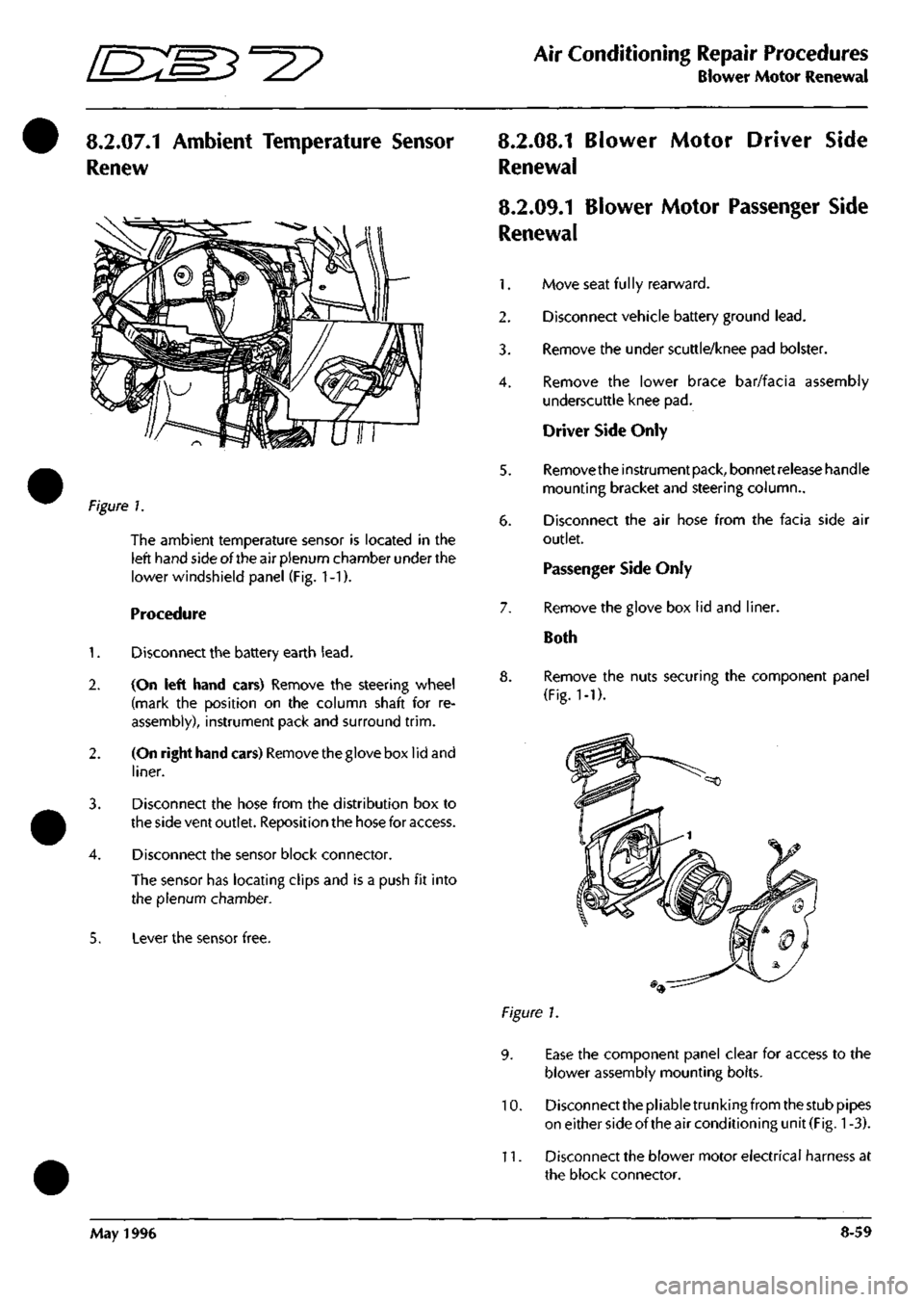
The ambient temperature sensor is located in the
left hand side of the air plenum chamber under the
lower windshield panel (Fig. 1-1).
Procedure
1.
Disconnect the battery earth
lead.
2.
(On left hand cars) Remove the steering wheel
(mark the position on the column shaft for re
assembly), instrument pack and surround
trim.
2.
(On right hand cars) Removethegloveboxlidand
liner.
3. Disconnect the hose from the distribution box to
the side vent outlet. Reposition the hose for access.
4.
Disconnect the sensor block connector.
The sensor has locating clips and is a push fit into
the plenum chamber.
5. Lever the sensor free.
8.2.08.1 Blower Motor Driver Side
Renewal
8.2.09.1 Blower Motor Passenger Side
Renewal
1.
Move seat
fu 1
ly rearward.
2.
Disconnect vehicle battery ground
lead.
3. Remove the under scuttle/knee pad bolster.
4.
Remove the lower brace bar/facia assembly
underscuttle knee pad.
Driver Side Only
5. Removetheinstrumentpack, bonnetreieasehandle
mounting bracket and steering column..
6. Disconnect the air hose from the facia side air
outlet.
Passenger Side Only
7. Remove the glove box lid and liner.
Both
8. Remove the nuts securing the component panel
(Fig.
1-1).
Figure 1.
9. Ease the component panel clear for access to the
blower assembly mounting bolts.
10.
Disconnect the pliable trunking from the stub pipes
on either side of the air conditioning unit
(Fig.
1
-3).
11.
Disconnect the blower motor electrical harness at
the block connector.
May 1996 8-59
Page 339 of 421
Air Conditioning Repair Procedures
Water Temperature Switch/Heater Matrix Renew •=2?
8.2.12.1 Water Temperature Switch
Renewal
1.
Disconnect the battery earth
lead.
2.
Un-clip and remove the left hand underscuttle
casing.
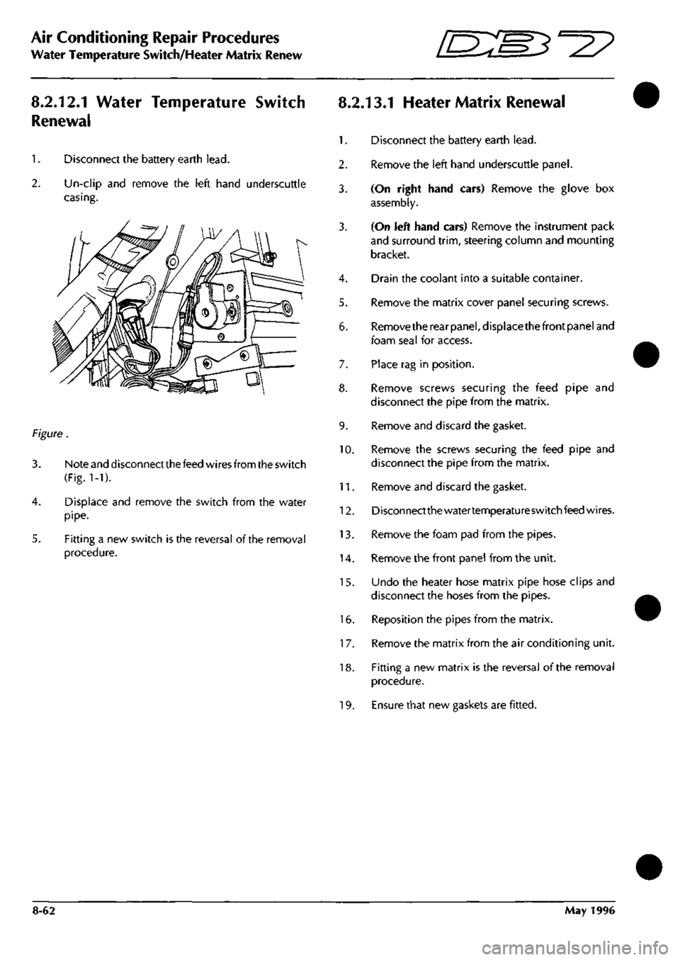
Figure.
3. Note and disconnect the feed wires from the switch
(Fig.
1-1).
4.
Displace and remove the switch from the water
pipe.
5. Fitting a new switch is the reversal of the removal
procedure.
8.2.13.1 Heater Matrix Renewal
1.
Disconnect the battery earth
lead.
2.
Remove the left hand underscuttle panel.
3. (On right hand cars) Remove the glove box
assembly.
3. (On left hand cars) Remove the instrument pack
and surround
trim,
steering column and mounting
bracket.
4.
Drain the coolant into a suitable container.
5. Remove the matrix cover panel securing screws.
6. Removethe rear
panel,
displacethefront panel and
foam seal for access.
7. Place rag in position.
8. Remove screws securing the feed pipe and
disconnect the pipe from the matrix.
9. Remove and discard the gasket.
10.
Remove the screws securing the feed pipe and
disconnect the pipe from the matrix.
11.
Remove and discard the gasket.
12.
Disconnectthewatertemperatureswitchfeedwires.
13.
Remove the foam pad from the pipes.
14.
Remove the front panel from the unit.
15.
Undo the heater hose matrix pipe hose clips and
disconnect the hoses from the pipes.
16.
Reposition the pipes from the matrix.
1
7. Remove the matrix from the air conditioning unit.
18.
Fitting a new matrix is the reversal of the removal
procedure.
19.
Ensure that new gaskets are fitted.
8-62 May 1996