air conditioning ASTON MARTIN DB7 1997 Owner's Manual
[x] Cancel search | Manufacturer: ASTON MARTIN, Model Year: 1997, Model line: DB7, Model: ASTON MARTIN DB7 1997Pages: 421, PDF Size: 9.31 MB
Page 288 of 421
^7
Air Conditioning
Temperature Distribution System
Air Conditioning Function Switch
When AC, DEM or Re-circulation ^v is selected the system engages the Air conditioning compressor using the
electromagnetic clutch. The in-car temperature is automatically corrected to the pre selected level by the system
sensors.
When MAN (manual mode) is selected it provides the operator selection of fan speed and in-car temperature
selection facilities. The in-car temperature is not thermostatically corrected to a predetermined level by the system
sensors.
When ECO is selected the system is in economy mode which allows the fan speed and heating levels to be selected
but gives no cooling. The air conditioning compressor is not engaged putting a minimum load on the engine.
When manual re-circulation is selected the blower flaps are closed and only that air which is in the vehicle is re
circulated.
When the ignition is turned off the blower flaps revert to the fresh air position.
Refrigeration Cycle
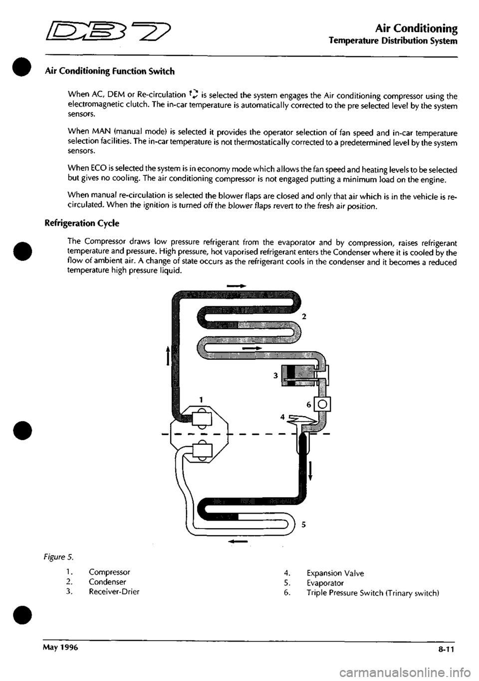
The Compressor draws low pressure refrigerant from the evaporator and by compression, raises refrigerant
temperature and pressure. High pressure, hot vaporised refrigerant enters the Condenser where it is cooled by the
flow of ambient air. A change of state occurs as the refrigerant cools in the condenser and it becomes a reduced
temperature high pressure liquid.
Figure 5.
1.
2.
3.
Compressor
Condenser
Receiver-Drier
4.
Expansion Valve
5. Evaporator
6. Triple Pressure Switch (Trinary switch)
May 1996 8-11
Page 289 of 421
Air Conditioning //~-->> ^/zz:^^ • ^ ^
General Svstem Procedures ' —"^ ^ '^ General System Procedures
From the condenser the liquid passes into the Receiver-Drier which has three functions:
• Storage vessel for varying system refrigerant demands.
• Filter to remove system contaminants.
• Moisture removal via the desiccant.
With the passage through the receiver-drier completed the, still high pressure liquid refrigerant, enters the Expansion
Valve where it is metered through a controlled orifice which has the effect of reducing the pressure and temperature.
The refrigerant, now in a cold atomised state, flows into the Evaporator and cools the air which is passing through
the matrix.
As heat is absorbed by the refrigerant it once again changes state, into a vapour, and returns to the compressor for
the cycle to be repeated (Fig. 5).
There is an automatic safety valve incorporated in the compressor which operates should the system pressure be
in excess of
41
bar. The valve re-seats when the pressure drops below 35 bar.
Note: The division of HIGH and LOW side is simply the
system pressure
differential created by the
compressor
discharge
(pressure),
suction
(inlet)
ports and
the
relative inlet and outlet
ports
of the
expansion
valve.
This
differential is critical to
system
fault
diagnosis
and efficiency checks.
System Protection
The trinary pressure switch, located in the liquid line, cuts electrical power to the compressor clutch if the system
pressure is outside of the range of 2 Bar
(1
st Function) to 27 Bar (2nd Function). The third function is to switch on
the cooling fans when pressure exceeds 20 bar.
General System Procedures
Leak Test
Faults associated with low refrigerant charge weight and low pressure may be caused by leakage. Leaks traced to
mechanical connections may be caused by torque relaxation or joint face contamination. Evidence of oil around
such areas is an indicator of leakage. When checking for non visible leaks use only a dedicated Refrigerant El 34A
electronic analyser and apply the probe all round the joint connection. Should a leak be traced to a joint, check that
the fixing is secured to the correct tightening torque before any other action is taken.
Do not forget to check the compressor shaft seal and evaporator.
Note: Never
use
a dedicated
CFC 12
or
naiced
flame type
analyser.
Charge Recovery (System Depressurisation)
The process of refrigerant recovery depends on the basic characteristics of your chosen recovery-recycle-recharge
equipment, therefore, follow the manufacturers instructions carefully. Remember that compressor oil may be drawn
out of the system by this process, take note of the quantity recovered so that it may be replaced.
CAUTION: Observe all relevant safety requirements.
• Do not vent refrigerant directly to atmosphere and always use approved recovery-recycle-recharge
equipment.
• Wear suitable eye and skin protection.
• Do not mix the refrigerant with CFC 12.
• Take note of the amount of recovered refrigerant, it indica
tes the
state of the
system
and
thus the
magnitude
of any problem.
8-12 May 1996
Page 290 of 421
^2?
Air Conditioning
General System Procedures
Evacuating the System
This process, the removal of unwanted air and moisture, is critical to the correct operation of the air conditioning
system.
The procedures depends on the characteristics of the recovery-recycle-recharge equipment and must be
carried out exactly in accordance with the manufacturers instructions.
Moisture can be highly destructive and may cause internal blockages due to freezing, but more importantly, water
suspended in the PAG oil will damage the compressor. Once the system has been opened for repairs, or the
refrigerant charge recovered, all traces oi moisture must be removed before recharging with new or recycled
refrigerant.
Adding Compressor Lubricating Oil
Oil can be added by three methods, two of which are direct into the system
• via the recovery-recycle-recharge station
• by proprietary oil injector.
Equipment manufacturer's instructions must be adhered to when using direct oil introduction.
The third method may be required because of rectification work to the existing compressor, or the need to fit a new
compressor. From an existing compressor, drain the oil into a measuring cylinder and record the amount. Flush the
unit out with fresh PAG oil and drain thoroughly. Refill the compressor with the same amount of PAG oil that was
drained out originally and plug all orifices immediately ready for refitting to the vehicle. The transit lubricating oil
must be drained and discarded from a new compressor before it may be fitted. An adjustment should be made to
the system oil level by taking into account:
• the quantity found in the original compressor
• the quantity deposited in the recovery equipment oil separator from the charge recovery operation.
Typically, 80 ml can be drained from the original compressor and 30 ml found in the oil separator; the sum of these
volumes (80 + 30 = 110 ml) is the amount of fresh PAG oil that must be put into the new compressor prior to fitting.
Hote:
The
discrepancy
between
this
figure
and
the
nominal capacity of
135
ml is
caused
by normally not
recoverable
oil being
trapped in
components
such
as
the receiver-drier or
evaporator.
The above statements are only true if there is no evidence of a leak. Where a leak has been detected and rectified,
the compressor must be refilled with the specified quantity.
Caution: Always decant
fresh
oil from a sealed container and do not leave oil exposed to the
atmosphere.
PAG oil is very
hygroscopic
(absorbs
water) and rapidly
attracts
atmospheric moisture.
PAG oil must
NEVER
be mixed with mineral
based
oils.
Do not
reuse
oil following a recovery cycle,
dispose
of it
safely.
Depending on the state of the air conditioning system immediately prior to charge recovery and the rate of recovery,
an amount of oil is drawn out with the refrigerant. The quantity is approximately 30 to 40 mi; this may vary, and
the figure is given only for guidance. It is most important that the oil separator vessel in the recovery equipment is
clean and empty at the start of the process so that the amount drawn out may be accurately measured.
May 1996 8-13
Page 291 of 421
Air Conditioning //—->> "^^Izz^^ • ^ ^
General System Procedures L ^—/ ' —^ ^./^
Adding Refrigerant
In order that the air conditioning system may operate efficiently it must contain a full refrigerant charge. The
indications of some system defects, and the results of certain tests, shows that
a
low charge
is
the most probable cause
of the fault. In such cases the charge shou
Id
be recovered from the
system,
the weight noted, and the correct amount
installed.
Note: Never attempt to
guess the
amount of refrigerant in
a
system.
Always recover and
recharge
with
the
correct
charge
weight,
this is the only
accurate
method.
Caution: If oil is drawn out during the recovery
process,
the correct amount can be added directly from your
recovery-recycle-
recharge station
(if so
equipped)
prior to the charging
process.
It must be
stressed
that the need to protect
compressor
oil from
moisture is vital, observe
the procedures
in Handling Lubricating Oil.
Warning: Liquid refrigerant boils at -29°C (-20°F) at atmospheric pressure. Serious injury, even blindness, can occur if
the refrigerant comes into contact with the eyes.
Goggles and gloves must be warn while working with refrigerant.
First Aid
If refrigerant should contact the eyes or
skin,
bathe the eyes or affected area with cold water for several minutes. Do
not rub. As soon as possible thereafter, obtain treatment from a doctor or eye specialist.
8-14 May 1996
Page 292 of 421
Air Conditioning
Functional Check
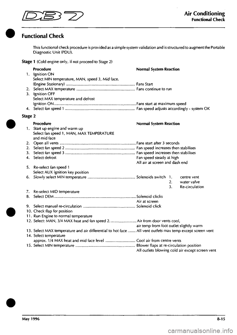
Functional Check
This functional check procedure is provided as a simple system validation and is structured to augment the Portable
Diagnostic Unit (PDU).
Stage 1 (Cold engine only, if not proceed to Stage 2)
Procedure Normal System Reaction
1.
Ignition ON
Select MIN temperature, MAN, speed 3, Mid face.
(Engine Stationary) Fans Start
2.
Select MAX temperature Fans continue to run
3. Ignition OFF
Select MAX temperature and defrost
Ignition ON Fans start at maximum speed
4.
Select fan speed
1
Fan speed adjusts accordingly - system OK
Stage 2
Procedure Normal System Reaction
1.
Start up engine and warm up
Select fan speed 1, MAN, MAX TEMPERATURE
and mid face
2.
Open all vents Fans start after 3 seconds
2.
Select fan speed 2 Fan speed increases then stabilises
3. Select fan speed 3 Fan speed increases then stabilises
4.
Select defrost Fan speed steady at high
All air at screen and dash end
5. Re-select fan speed 1
Select AUX ignition key position
6. Slowly select MIN temperature Solenoids switch 1. centre vent
2.
water valve
3. Re-circulation
7. Re-select MID temperature
8. Select DEM Solenoid clicks
Air at screen
9. Select manual re-circulation Solenoid click
10.
Check flap for position
11.
Run Engine to normal temperature
12.
Select: MAN, 3/4 MAX heat and fan speed 2 Air from door vents
cool,
air temp from foot outlet slightly warm
13.
Select MAX temperature and air differential to hot face All vent outlets max temp except screen vent
14.
Select temperature
approx. 1/4 MAX heat and mid face level Cool air from centre vents
15.
Select MIN temperature Blower flaps at re-circulation position
All outlets blowing cold air except screen vent
May 1996 8-15
Page 293 of 421
Air Conditioning //—^ ^ci^^ • ^ ^
Fnnrtlnn;il fhprk I *-/ -^ r <
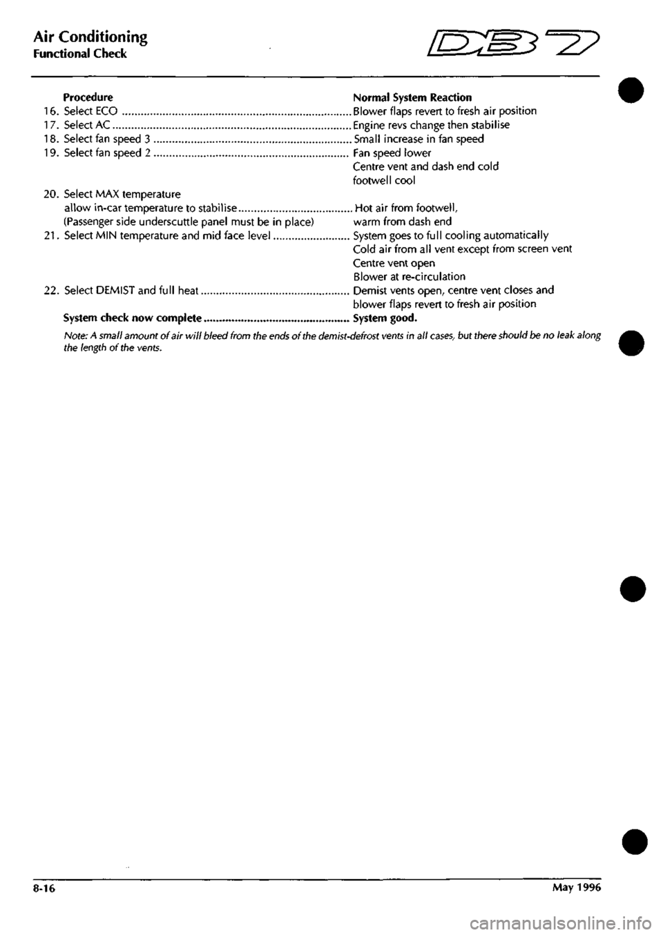
Procedure Normal System Reaction
16.
Select ECO Blower flaps revert to fresh air position
17.
Select AC Engine revs change then stabilise
18.
Select fan speed 3 Small increase in fan speed
19.
Select fan speed 2 Fan speed lower
Centre vent and dash end cold
footwell cool
20.
Select MAX temperature
allow in-car temperature to stabilise Hot air from footwell,
(Passenger side underscuttle panel must be in place) warm from dash end
21.
Select MIN temperature and mid face level System goes to full cooling automatically
Cold air from all vent except from screen vent
Centre vent open
Blower at re-circulation
22.
Select DEMIST and full heat Demist vents open, centre vent closes and
blower flaps revert to fresh air position
System check now complete System good.
Note: A small amount of air will bleed from the
ends
of the
demist-defrost vents
in all
cases,
but there should be no leak along
the length of the vents.
8-16 May 1996
Page 294 of 421
^=2?
Air Conditioning
System Trouble Shooting
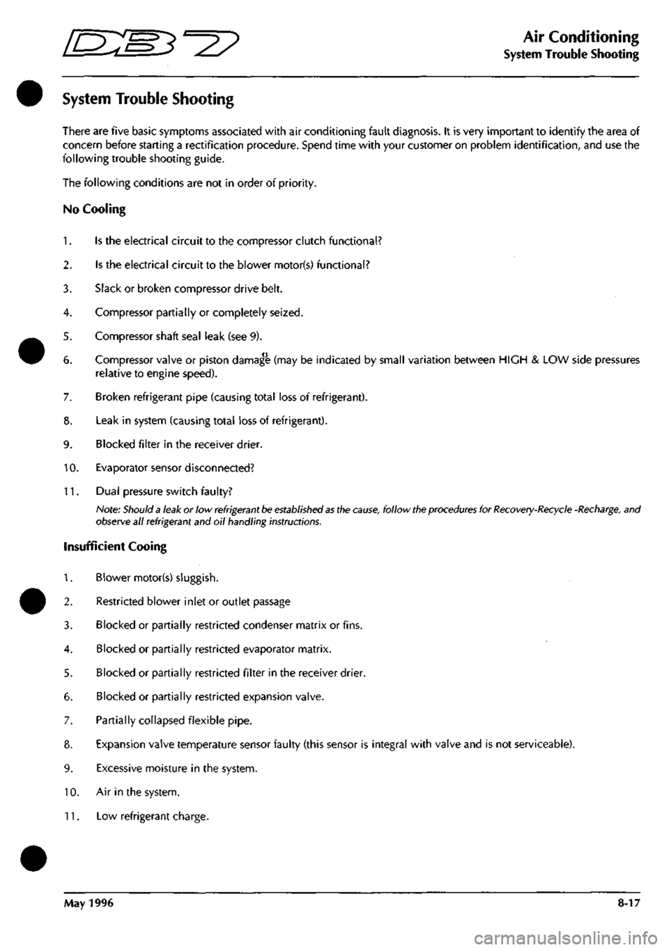
System Trouble Shooting
There are five basic symptoms associated with air conditioning fault diagnosis. It is very important to identify the area of
concern before starting a rectification procedure. Spend time with your customer on problem identification, and use the
following trouble shooting guide.
The following conditions are not in order of priority.
No Cooling
1.
Is the electrical circuit to the compressor clutch functional?
2.
Is the electrical circuit to the blower motor(s) functional?
3. Slack or broken compressor drive belt.
4.
Compressor partially or completely seized.
5. Compressor shaft seal leak (see 9).
6. Compressor valve or piston damag^ (may be indicated by small variation between HIGH & LOW side pressures
relative to engine speed).
7. Broken refrigerant pipe (causing total loss of refrigerant).
8. Leak in system (causing total loss of refrigerant).
9. Blocked filter in the receiver drier.
10.
Evaporator sensor disconnected?
11.
Dual pressure switch faulty?
Note:
Should a
leak or low
refrigerant be established as
the
cause,
follow
the procedures
for
Recovery-Recycle
-Recharge,
and
observe all refrigerant and oil handling instructions.
insufficient Cooing
1.
Blower motor(s) sluggish.
2.
Restricted blower inlet or outlet passage
3. Blocked or partially restricted condenser matrix or fins.
4.
Blocked or partially restricted evaporator matrix.
5. Blocked or partially restricted filter in the receiver drier.
6. Blocked or partially restricted expansion valve.
7. Partially collapsed flexible pipe.
8. Expansion valve temperature sensor faulty (this sensor is integral with valve and is not serviceable).
9. Excessive moisture in the system.
10.
Air in the system.
11.
Low refrigerant charge.
May 1996 8-17
Page 295 of 421
Air Conditioning
/J=y>f^^^
—p )
System Trouble Shooting
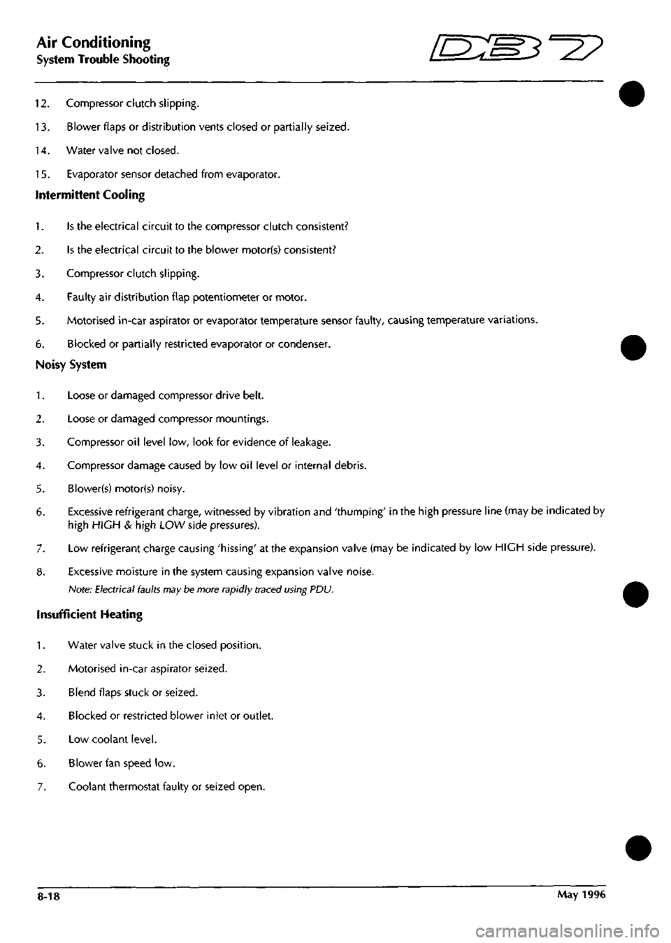
12.
Compressor clutch slipping.
13.
Blower flaps or distribution vents closed or partially seized.
14.
Water valve not closed.
15.
Evaporator sensor detached from evaporator.
Intermittent Cooling
Is the electrical circuit to the compressor clutch consistent?
2.
Is the electrical circuit to the blower motor(s) consistent?
3. Compressor clutch slipping.
4.
Faulty air distribution flap potentiometer or motor.
5. Motorised in-car aspirator or evaporator temperature sensor faulty, causing temperature variations.
6. Blocked or partially restricted evaporator or condenser.
Noisy System
1.
Loose or damaged compressor drive belt.
2.
Loose or damaged compressor mountings.
3. Compressor oil level low, look for evidence of leakage.
4.
Compressor damage caused by low oil level or internal debris.
5. Blower(s) motor(s) noisy.
6. Excessive refrigerant charge, witnessed by vibration and 'thumping' in the high pressure line (may be indicated by
high HIGH & high LOW side pressures).
7. Low refrigerant charge causing 'hissing' at the expansion valve (may be indicated by low HIGH side pressure).
8. Excessive moisture in the system causing expansion valve noise.
Note;
Electrical faults
may
be more rapidly traced using PDU.
Insufficient Heating
1.
Water valve stuck in the closed position.
2.
Motorised in-car aspirator seized.
3. Blend flaps stuck or seized.
4.
Blocked or restricted blower inlet or outlet.
5. Low coolant level.
6. Blower fan speed low.
7. Coolant thermostat faulty or seized open.
8-18 May 1996
Page 296 of 421
^2?
Air Conditioning
Electronic Control Module
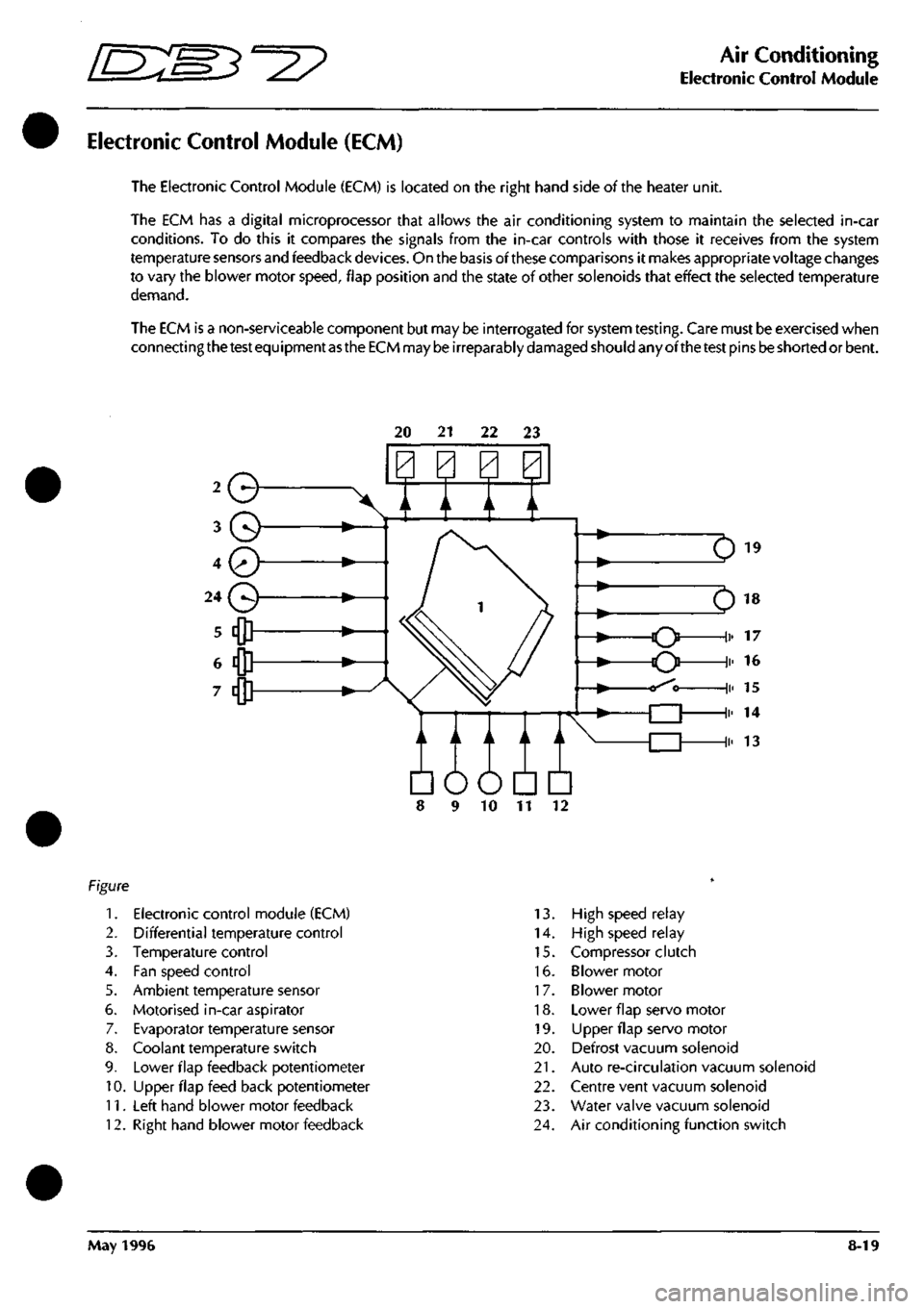
Electronic Control Module (ECM)
The Electronic Control Module (ECM) is located on the right hand side of the heater unit.
The ECM has a digital microprocessor that allows the air conditioning system to maintain the selected in-car
conditions. To do this it compares the signals from the in-car controls with those it receives from the system
temperature sensors and feedback
devices.
On the basis of these comparisons it makes appropriate voltage changes
to vary the blower motor
speed,
flap position and the state of other solenoids that effect the selected temperature
demand.
The ECM is a non-serviceable component but may be interrogated for system
testing.
Care must be exercised when
connecting
the test
equipment
as the ECM
may
be
irreparably
damaged
should any ofthe
test
pins
be
shorted or bent.
20 21 22 23
Q
A / A \/
Em
10 11
1.
Electronic control module (ECM)
2.
Differential temperature control
3. Temperature control
4.
Fan speed control
5. Ambient temperature sensor
6. Motorised in-car aspirator
7. Evaporator temperature sensor
8. Coolant temperature switch
9. Lower flap feedback potentiometer
10.
Upper flap feed back potentiometer
11.
Left hand blower motor feedback
12.
Right hand blower motor feedback
13.
High speed relay
14.
High speed relay
15.
Compressor clutch
16.
Blower motor
17.
Blower motor
18.
Lower flap servo motor
19.
LIpper flap servo motor
20.
Defrost vacuum solenoid
21.
Auto re-circulation vacuum solenoid
22.
Centre vent vacuum solenoid
23.
Water valve vacuum solenoid
24.
Air conditioning function switch
May 1996 8-19
Page 297 of 421
Air Conditioning
Electronic Control Module r^^?
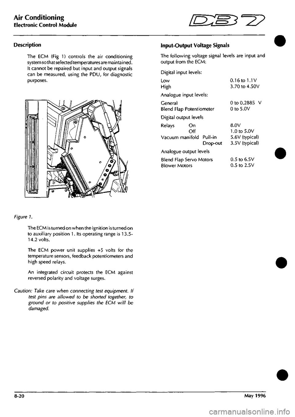
Description
The ECM (Fig 1) controls the air conditioning
system so that selected temperaturesare maintained.
It cannot be repaired but input and output signals
can be measured, using the PDU, for diagnostic
purposes.
Input-Output Voltage Signals
The following voltage signal levels are input and
output from the ECM:
Digital input levels:
Low
High
Analogue input levels:
General
Blend Flap Potentiometer
Digital output levels
Relays On
Off
Vacuum manifold Pull-in
Drop-out
Analogue output levels
Blend Flap Servo Motors
Blower Motors
0.16 to 1.1V
3.70 to 4.50V
0 to 0.2885 V
0 to 5.0V
8.0V
1.0 to 5.0V
5.6V (typical)
3.5V (typical)
0.5 to 6.5V
0.5 to 2.5V
figure 1.
The ECM
is
turned on when the ignition
is
turned on
to auxiliary position 1. its operating range is 13.5-
14.2 volts.
The ECM power unit supplies +5 volts for the
temperature sensors, feedback potentiometers and
high speed relays.
An integrated circuit protects the ECM against
reversed polarity and voltage surges.
Caution: Take care when connecting test equipment. If
test pins are allowed to be shorted together, to
ground or to positive supplies the ECM will be
damaged.
8-20 May 1996