belt ASTON MARTIN DB7 1997 Owner's Manual
[x] Cancel search | Manufacturer: ASTON MARTIN, Model Year: 1997, Model line: DB7, Model: ASTON MARTIN DB7 1997Pages: 421, PDF Size: 9.31 MB
Page 225 of 421

Electrics
Seat Belt Pretensioner
Check the continuity of
the
line from pretensioner
control module pin 2 to instrument pack green
connector pin 2.
If continuity is approximately
OQ,
go to step 5.
If the line resistance
is
significantly greater
than
OQ,
service the wiring as necessary. Reconnect all
components and test the vehicle to ensure that the
problem is resolved.
Ifthe lamp
and
wiring
checks are
good,
the
fault lies
in the instrument pack or in the control module.
Replace the control module and retest. Ifthe fault
persists, replace the instrument
pack.
Reconnectall
components and test the vehicle to ensure that the
problem is resolved.
Pretensioner Control Module Internal
Faults
The following codes indicate internal faults within the
pretensioner control module.
0209 Safing sensor error
030A Temperature sensor error
0D13 Capacitor voltage error
0D14 Capacitor capacitance
0D09 Energy reserve switch
0D1E Energy shutdown switch
050E Seatbelt pretensioner switch error
0109 Accelerometer function
01OA Acceleration out of range
01 OB
Acceierometer offset
OAOC Analogue voltage error
090A EEPROM not programmed
0909 EEPROM checksum
090C RAM check error
060E Warning lamp driver error
0A09 Communications error
OAOA External watchdog error
OAOB External watchdog time out
020A Safing sensor not closed
If any of the above codes are logged, replace the
pretensioner control module.
September 1996 6-109
Page 227 of 421
3-^?
Electrics
Seat Removal/Replacement 97.5 MY
6.6.03
Seat Removal 97.5 MY
Description
The 97.5 MY front seats are common to the DB7
Coupe
and
Volante
models.
Seat
switch
assembi ies
are located on the outboard side of both driver and
passenger
seats.
The front switch controls fore and
aft movement and the seat height adjustment. The
centre switch controls the recline adjustment. The
rear switch
controls
the
lumbar support adjustment.
The seat
heater switches are mounted on the centre
console, forward of the gear selector
lever.
Only one of
the
slide,
recline or height motors can
be driven under manual control at any one time.
Each seat switch pack is hard wired to the relevant
Seat Control
Module
beneath each
seat.
The
module
outputs are hard wired to the seat motors.
Removal
WARNING -
Seat
belt
Pretensioners
(if fitted):
To avoid the possibility
of
personal
injury
caused
by accidental deployment of the seat belt
pretensioner,
disconnect
the
vehicle battery and
wait at
least
10
minutes
for all
voltages
to fully
discharge
before working on the
pretensioner
system.
This covers the possibility
of
the normal
capacitor
discharge
circuits being inoperative and
failing to discharge the detonator capacitor when
instructed
to
do
so.
Procedure
1.
Motortheseatto
its
maximum forward position and
remove the fixings at the rear of the slides.
2.
Motor the seat to its maximum rearward position
and remove the front seat slide fixings.
3. Disconnect the battery
ground
(black)
lead.
Wait at
least 10 minutes for the pretensioner power supply
to fully discharge before working on the seat if a
pretensioner is fitted.
Note: Disconnect the battery within 12 seconds of
switching off the ignition to avoid the alarm siren sounding.
4.
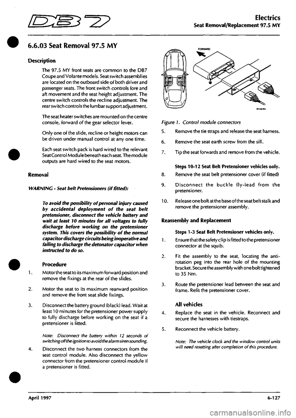
Disconnect the two harness connectors from the
seat control module. Also disconnect the yellow
connector from the pretensioner control module if
a pretensioner is fitted.
Figure 1. Control module connectors
5. Remove the tie straps and release the seat harness.
6. Remove the seat earth screw from the
sill.
7. Tip the seat forwards and remove from the vehicle.
Steps 10-12 Seat Belt Pretensioner vehicles only.
8. Remove the seat belt pretensioner cover (if fitted)
9. Disconnect the buckle fly-lead from the
pretensioner.
10.
Release
one
bolt at
the
base of the
seat
belt stalk and
remove the pretensioner assembly.
Reassembly and Replacement
Steps 1-3 Seat Belt Pretensioner vehicles only.
1.
Ensurethatthesafetyclipisfittedtothepretensioner
connector at the squib.
2.
Fit the assembly to the seat, locating the
anti-
rotation peg into the rear hole of the mounting
bracket.
Securethe
assembly with
one
bolttightened
to 35 Nm.
3. Route the pretensioner lead between the seat and
frame.
Refit the pretensioner
cover.
All vehicles
4.
Replace the seat in the vehicle. Reconnect and
secure the harnesses with tiestraps.
5. Reconnect the vehicle battery.
Note:
The vehicle clock and the window control units
will
need resetting after completion
of
this
procedure.
April 1997 6-127
Page 228 of 421
Electrics
Seat Control Module Removal/Replacement 97.5 MY 'O "3^2?
Switch on the ignition and checi< that the airbag
warning lamp comes on when the ignition is
switched on and extinguishes after approximately
six seconds indicating satisfactory completion of
the pretensioner and airbag system self
tests.
Fit
the front
seat
retaining screws ensuring
a
1.2mm
gap between the screw heads
and
the
slides.
Power
the seat forward and refit the rear screws.
Caution:
Centralise the
rear
fixing holes
with the
body weld
nuts
prior to
inserting the
bolts.
Torque the rear screws to 25 Nm. Power the seat
backwards. Torque the front screws to 25 Nm.
Motor the seat through its full range of movement
to ensure correct
operation.
6.6.08
Seat Control Module 97.5 MY
Removal
WARNING -
Seat
belt
Pretensioners
(if
fitted):
To avoid the possibility
of
personal injury caused
by accidental deployment of the seat belt
pretensioner,
disconnect
the
vehicle battery and
wait at
least
10
minutes
for all
voltages
to fully
discharge
before
working
near the
pretensioner
system.
This covers
the
possibility
of
the
normal
capacitor
discharge circuits
being
inoperative and
failing to discharge the detonator capacitor when
instructed
to
do
so.
1.
Lower the door window and open the relevant
door. Disconnect
the
battery ground cableand wait
for 10 minutes if
a
pretensioner
is
fitted.
Otherwise,
proceed immediately to step 2.
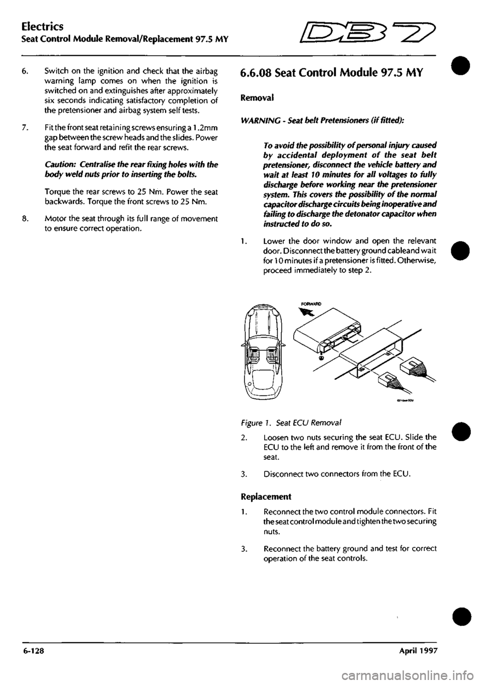
(ei-SMiECu
Figure!.
Seat ECU Removal
2. Loosen two nuts securing the seat ECU. Slide the
ECU to the left and remove it from the front of the
seat.
3. Disconnect two connectors from the ECU.
Replacement
1.
Reconnect the two control module connectors. Fit
the seat control
moduleand
tighten
thetwo securing
nuts.
3. Reconnect the battery ground and test for correct
operation of the seat controls.
6-128 April 1997
Page 282 of 421
Em^^^?
Air Conditioning
General Description
General Description
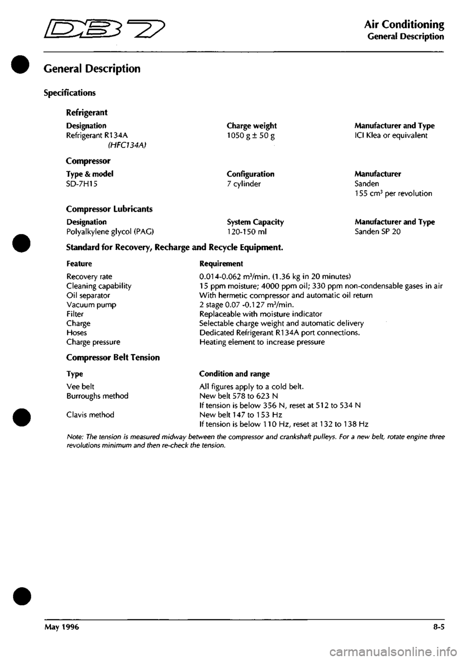
Specifications
Refrigerant
Designation
Refrigerant R134A
(HFCUAA)
Compressor
Type
&
model
SD-7H15
Charge weight
1050g±50g
Configuration
7 cylinder
Compressor Lubricants
Designation
Polyalkylene glycol
(PAG)
Standard
for
Recovery, Recharge
and
Recycle Equipment,
System Capacity
120-150
ml
Manufacturer and Type
ICI Klea
or
equivalent
Manufacturer
Sanden
155 cm^
per
revolution
Manufacturer and Type
Sanden SP
20
Feature
Recovery rate
Cleaning capability
Oil separator
Vacuum pump
Filter
Charge
Hoses
Charge pressure
Compressor Belt Tension
Type
Vee belt
Burroughs method
Clavis method
Requirement
0.014-0.062
mVmin.
(1.36 kg in 20
minutes)
15
ppm
moisture; 4000
ppm oil; 330 ppm
non-condensable gases
in air
With hermetic compressor and automatic
oil
return
2 stage
0.07
-0.127 mVmin.
Replaceable with moisture indicator
Selectable charge weight and automatic delivery
Dedicated Refrigerant R134A port connections.
Heating element
to
increase pressure
Condition and range
All figures apply
to a
cold belt.
New belt
578 to 623 N
If tension
is
below
356 N,
reset
at 512 to 534 N
New belt
147 to 153 Hz
If tension
is
below
110 Hz,
reset
at 132 to 138 Hz
Note:
The
tension
is
measured
midway between the
compressor
and crankshaft pulleys. For a new
belt,
rotate engine three
revolutions minimum and then re-check the tension.
May 1996
8-5
Page 294 of 421
^=2?
Air Conditioning
System Trouble Shooting
System Trouble Shooting
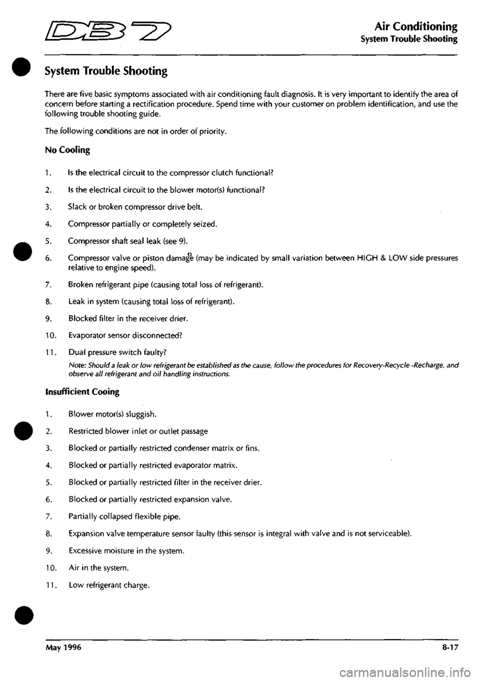
There are five basic symptoms associated with air conditioning fault diagnosis. It is very important to identify the area of
concern before starting a rectification procedure. Spend time with your customer on problem identification, and use the
following trouble shooting guide.
The following conditions are not in order of priority.
No Cooling
1.
Is the electrical circuit to the compressor clutch functional?
2.
Is the electrical circuit to the blower motor(s) functional?
3. Slack or broken compressor drive belt.
4.
Compressor partially or completely seized.
5. Compressor shaft seal leak (see 9).
6. Compressor valve or piston damag^ (may be indicated by small variation between HIGH & LOW side pressures
relative to engine speed).
7. Broken refrigerant pipe (causing total loss of refrigerant).
8. Leak in system (causing total loss of refrigerant).
9. Blocked filter in the receiver drier.
10.
Evaporator sensor disconnected?
11.
Dual pressure switch faulty?
Note:
Should a
leak or low
refrigerant be established as
the
cause,
follow
the procedures
for
Recovery-Recycle
-Recharge,
and
observe all refrigerant and oil handling instructions.
insufficient Cooing
1.
Blower motor(s) sluggish.
2.
Restricted blower inlet or outlet passage
3. Blocked or partially restricted condenser matrix or fins.
4.
Blocked or partially restricted evaporator matrix.
5. Blocked or partially restricted filter in the receiver drier.
6. Blocked or partially restricted expansion valve.
7. Partially collapsed flexible pipe.
8. Expansion valve temperature sensor faulty (this sensor is integral with valve and is not serviceable).
9. Excessive moisture in the system.
10.
Air in the system.
11.
Low refrigerant charge.
May 1996 8-17
Page 295 of 421
Air Conditioning
/J=y>f^^^
—p )
System Trouble Shooting
12.
Compressor clutch slipping.
13.
Blower flaps or distribution vents closed or partially seized.
14.
Water valve not closed.
15.
Evaporator sensor detached from evaporator.
Intermittent Cooling
Is the electrical circuit to the compressor clutch consistent?
2.
Is the electrical circuit to the blower motor(s) consistent?
3. Compressor clutch slipping.
4.
Faulty air distribution flap potentiometer or motor.
5. Motorised in-car aspirator or evaporator temperature sensor faulty, causing temperature variations.
6. Blocked or partially restricted evaporator or condenser.
Noisy System
1.
Loose or damaged compressor drive belt.
2.
Loose or damaged compressor mountings.
3. Compressor oil level low, look for evidence of leakage.
4.
Compressor damage caused by low oil level or internal debris.
5. Blower(s) motor(s) noisy.
6. Excessive refrigerant charge, witnessed by vibration and 'thumping' in the high pressure line (may be indicated by
high HIGH & high LOW side pressures).
7. Low refrigerant charge causing 'hissing' at the expansion valve (may be indicated by low HIGH side pressure).
8. Excessive moisture in the system causing expansion valve noise.
Note;
Electrical faults
may
be more rapidly traced using PDU.
Insufficient Heating
1.
Water valve stuck in the closed position.
2.
Motorised in-car aspirator seized.
3. Blend flaps stuck or seized.
4.
Blocked or restricted blower inlet or outlet.
5. Low coolant level.
6. Blower fan speed low.
7. Coolant thermostat faulty or seized open.
8-18 May 1996
Page 320 of 421
^2?
Air Conditioning
System Checking with the Manifold Gauge Set
Compressor Malfunction
Complaint.
Cooling is not adequate.
Condenser Malfunction or System Overcharge
Complaint.
Little or no cooling. Overheating of the engine may
also be noted.
BLUE LOW SIDE
BLUE
LOW SIDE BED HICH SIDE
Condition
1.
The low side gauge reading is too
high.
2.
The high gauge reading is too low.
3. The sight glass is free of bubbles and the system is
fully charged.
4.
The discharge air from the evaporator is not
sufficiently
cool.
Diagnosis.
Internal leak in the compressor.
Correction.
1.
Depressurise the system.
2.
Renew the compressor and the drier bottle.
3. Evacuate the system using a vacuum pump.
4.
Charge the system with new refrigerant.
5. Operate the system and check the performance.
HIGH
Condition.
1.
The low side gauge reading excessively
high.
2.
The high side gauge reading is also excessively
high.
3. Bubbles may appear occasionally in the sight glass
and the liquid line to the evaporator is very hot.
4.
The discharge air from the evaporator is warm.
Diagnosis.
The condenser not operating correctly through lack
of cooling caused by too high a high side pressure.
The system may have either
a
normal or overcharge
of refrigerant.
Correction.
1.
Checkthecompressordrivebeltforcorrecttension.
2.
Check the condenser for clogged air passages
preventing air flow through the condenser.
3. Inspect the condenser mounting for correct radiator
clearance.
4.
Check for correct fan operation.
5. Check the coolant pressure capfor correct type and
operation.
May 1996 8-43
Page 328 of 421
^?
Air Conditioning Repair Procedures
Compressor Removal
8.1.01.1 Compressor Removal/Renewal
Procedure
1.
Open the bonnet and fit a wing cover.
2.
Depressurise the air conditioning system.
3.
6.
7.
8.
9.
Disconnect the low and high pressure hoses from
the rear of the compressor. Plug the hose ends to
prevent the ingress of dirt.
Remove the compressor pivot bolt securing nut.
Carefully separate the muffler from the compressor
and remove and discard the 'O' ring
seal.
Fit a blanking plug to the muffler and a blanking
plate to the compressor, fit and tighten the bolt that
secures blanking plate.
Raise the vehicle to working height on a ramp.
Figure 7.
10.
Slacken the compressor drive belt adjuster rod and
adjuster plate securing nuts and bolts (Fig.
1
-4, 5, 6
and 7)
11.
Slacken adjuster nut (Fig.
1
-10).
12.
Remove the nut and bolt (Fig. 1-4 and 5) from
adjuster plate (Fig. 1-3).
13.
Slacken trunnion nut and bolt (Fig.
1
-9 and 2) and
remove the adjuster rod (Fig. 1-1).
14.
Disconnect the compressor multi-plug.
1
5. Remove the compressor drive belt.
16.
Pivot the compressor away from engine, support
the compressor and remove the top pivot bolt and
lift the compressor clear of the vehicle.
17.
Removethemountingbracketsfromthecompressor.
26.
Lift the compressor up to the engine and fit the top
pivot bolt (Fig.
1
-2) from above.
27.
Attach adjustment rod loosely to the compressor
(Fig.
1
-1) with nut and bolt (Fig.
1
-6 and 7).
28.
Loosely attach adjustment plate (Fig. 1-3) to the
compressor with nut and bolt (Fig.
1
-4 and 5).
29.
Fit bolt (Fig.
1
-2) through trunnion (Fig.
1
-8) and fit
nut (Fig. 1-9) to the bolt.
30.
Fit the drive belt over the pulley, move the
compressor away from the engine to tension the
drive belt and lightly tighten the bolts and nuts.
31.
To obtain the correct tension on the drive belt
tighten adjuster nuts
(Fig.
1
-10). The belt
is
correctly
tensioned when a load of 59- 63.6 kg (130 -140 lb)
applied at the centre deflects the belt 4 mm.
32.
Ensure that all securing bolts and nuts are fully
tightened.
33.
Lowerthe vehicle to the ground.
34.
Remove the blanking plate and the blanking plugs
from the compressor.
36.
Fit new 'O' ring seals to the low and high pressure
hoses and connect them to the compressor. Fit the
retaining plate, fit and tighten the screw.
38.
Charge the air conditioning system.
39.
Remove the wing cover and close the bonnet.
May 1996 8-51
Page 352 of 421
^?
The Aston Martin Lagonda Diagnostic System
Contents
Installation Instructions
Introduaion 9-2
The Aston Martin Diagnostic System 9-2
Diagnostic System Cables 9-5
Base Station Installation 9-8
Problem Solving 9-16
Service Centres 9-21
Service and Maintenance 9-22
Technical Specifications 9-24
Operating Instructions
The Aston Martin Lagonda Diagnostic System 9-27
Software 9-29
Cable Setup 9-31
Diagnostic Sockets - 97 MY 9-31
Establishing Communications 9-32
System Menu Selections 9-32
PDU Use 9-32
Engine Diagnostics - 97 MY 9-33
Transmission Diagnostics 9-40
Climate Control Diagnostics 9-43
Anti-Lock Brakes Diagnostics 9-43
Passive Anti-Theft (PATS) Diagnostics 9-44
Airbag System Diagnostics 9-45
Seat Belt Pretensioner Diagnostics 9-47
Print Facility 9-49
Digital Multimeter 9-50
Diagnostic Trouble Codes 9-53
Datalogger 9-55
Datalogger Example 9-63
Training 9-66
OBD II Scan Tool 9-66
System Self Test 9-69
The Asterisk (*) Menu 9-69
System Setup 9-70
May 1996 9-1
Page 379 of 421
The Aston Martin Lagonda Diagnostic System
Users Guide o: "3^^?
PDU Functions
The PDU main menu provides access into the following functions:
Diagnostics
Training
Digital Multimeter
User Self Test
Diagnostics
On selecting'Diagnostics'from the main
menu,
the user will be prompted to enter the features and market specification
of the vehicle to be tested. Use of the diagnostics in each of the above areas is described later in this guide.
Diagnostics Menu - 95 Model Year
Engine
Anti-Lock Braking System
Vlenu - 97 Model Year
Engine Diagnostics
OBD II Scan Tool
Airbag
Seat Belt Pretensioner
•
•
•
•
Transmission
Engine Datalogger
Climate Control
PATS System
Climate Control
Transmission
Anti-Lock Braking System
Security
Digital Multimeter
The Digital Multimeter function provides the capabilityto measure voltage, current, resistance, frequency, pulse width,
pulse period, and duty cycle. These measurements are usually made using the PDU measurement probes. Measurements
may also be made using the module pin selection function on the Teves Mk
II
braking system and on the Air Conditioning
system.
Training
An on-screen programme is provided to train new users in the use of screen icons and in the use of the digital multiÂ
meter and datalogger functions.
User Self Test
In order to prove that the equpment is functioning correctly, a complete user self test is incorporated. The user is directed
to test the PDU and then to progressively connect each part of the PDU system which will be tested by the software.
Any fault identified during the test is notified to the user. If no faults are identified, the user is advised on the correct
functioning of the system.
PDU Power
Power for the PDU is supplied via an internal rechargeable battery pack which can keep the PDU operational for
approximately one hour when disconnected from the base station and the vehicle. In order to preserve PDU battery
charge, power to the screen backlight is automatically cut after five minutes of inactivity. The power ON indicator
remains lit, indicating that the PDU is in 'stand-by' mode. One touch of the screen will restore backlight power.
When connected to the base station, power is supplied to the PDU from the Electronic Module to recharge the PDU
battery pack as necessary.
On 95 MY vehicles, the Vehicle Battery Adaptor (VBA) is used to maintain PDU power.
On 97 MY vehicles, when connected via the MPA to either diagnostic socket on the vehicle, power is supplied via pin
4 (chassis ground) and pin 16 (battery power) to maintain PDU power at all times even when the vehicle ignition is
switched off.
On all model years, when connected to the air conditioning system using the VIA, the vehicle battery adaptor (VBA)
must also be used to maintain PDU power.
9-28 September 1996