wheel ASTON MARTIN DB7 1997 Owner's Manual
[x] Cancel search | Manufacturer: ASTON MARTIN, Model Year: 1997, Model line: DB7, Model: ASTON MARTIN DB7 1997Pages: 421, PDF Size: 9.31 MB
Page 394 of 421

^?
The Aston Martin Lagonda Diagnostic System
Users Guide
Climate Control Diagnostics
The air conditioning control module is located at the right
end of the air conditioning unit. Since this controller uses
a unique communications protocol, the PDU must be
connected directly to the unit via the Vehicle Inerface
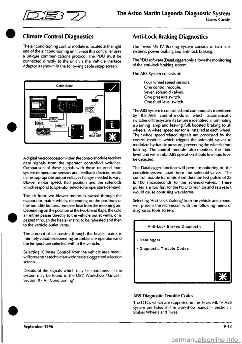
Adaptor as shown in the following cable setup screen.
Cable Setup
Adigitalmicroprocessorwithin the control module receives
data signals from the operator controlled switches.
Comparison of these signals with those returned from
system temperature sensors and feedback devices results
in the appropriate output voltage changes needed to vary:
Blower motor speed, flap position and the solenoids
which respond to operator selected temperature demand.
The air from two blower motors is passed through the
evaporator matrix which, depending on the positions of
the humidity buttons, removes heat from the incoming air.
Dependingon the position of the two blend flaps, the cold
air either passes directly to the vehicle outlet vents, or is
passed through the heater matrix to be reheated and then
to the vehicle outlet vents.
The amount of air passing through the heater matrix is
infinitely variable depending on ambienttemperature and
the temperature selected within the vehicle.
Selecting 'Climate Control' from the vehicle area menu,
will presentthetechnician with the dataloggertool selection
screen.
Details of the signals which may be monitored in the
system may be found in the DB7 Workshop Manual -
Section 8 - Air Conditioning'
Anti-Lock Braking Diagnostics
The Teves Mk IV Braking System consists of two sub
systems, power braking and anti-lock braking.
The PDU software(DataLogger) only allows the monitoring
of the anti-lock braking system.
The ABS System consists of:
Four wheel speed sensors.
One control module.
Seven solenoid valves.
One pressure switch.
One fluid level switch.
The ABS System
is
controlled and continuously monitored
by the ABS control module, which automatically
switchesoffthesystemifafailure is identified, illuminating
a warning lamp and leaving
full,
boosted braking to all
wheels. A wheel speed sensor is installed at each wheel.
Their wheel speed related signals are processed by the
control module, which triggers the solenoid valves to
modulate hydraulic pressure, preventing the wheels from
locking.
The control module also monitors the fluid
level and will inhibit ABS operation should lowfluid level
be detected.
The Datalogger function will permit monitoring of the
complete system apart from the solenoid valves. The
control module transmits short duration test pulses of 25
to 100 microseconds to the solenoid valves. These
pulses are too fast for the PDU to monitor and as a result
would cause confusing waveforms.
Selecting 'Anti-Lock Braking' from the vehicle area menu,
will present the technician with the following menu of
diagnostic tools screen:
Anti-Lock Brakes Diagnostic
Datalogger
Diagnostic Trouble Codes
o
ABS Diagnostic Trouble Codes
The DTCs which are supported in the Teves Mk IV ABS
system are listed in the workshop manual - Section 5
Brakes Wheels and Tyres.
September 1996 9-43
Page 395 of 421

The Aston Martin Lagonda Diagnostic System
Users Guide
Em^'^?
ABS Datalogger
The following signals in the Teves Mk IV ABS system may
be monitored using the datalogger function.
DTCs Number of DTCs Logged
The Diagnostic status manager (DSM) receives and
processes fault information and decides when a DTC
should be logged and the MIL turned on. The actual total
stored is indicated by the parameter.
FBRAKE Brake Switch
The signal from the brake switch is used by the CM to
ensure that traction control is inhibited when the brakes
are applied. The input circuitry within the CM is a
1
OK
pull-up to ignition voltage. When the switch is closed the
parameter is set to 1.
FLWS Front Left Wheel Speed Sensor
An indication sensor outputs a sinusoidal wave form 48
pulses per revolution. The output is processed by the CM
to control braking and traction. The sensor is continually
monitored for open and short failure and operating range.
If its output exceeds 330km/h it is deemed to be faulty and
the CM is disabled. The parameter tracks the sensor
weaveform through 255 steps.
FRWS Front Right Wheel Speed Sensor
An indication sensor outputs a sinusoidal wave form 48
pulses per revolution. The output is processed by the CM
to control braking and traction. The sensor is continually
monitored for open and short failure and operating range.
If its output exceeds 330km/h it
is
deemed to be faulty and
the CM is disabled. The parameter tracks the sensor
weaveform through 255 steps.
RLWS Rear Left Wheel Speed Sensor
An indication sensor outputs a sinusoidal wave form 48
pulses per revolution. The output is processed by the CM
to control braking and traction. The sensor is continually
monitored for open and short failure and operating range.
If its output exceeds 330km/h it
is
deemed to be faulty and
the CM is disabled. The parameter tracks the sensor
weaveform through 255 steps.
RRWS Rear Right Wheel Speed Sensor
An indication sensor outputs a sinusoidal wave form 48
pulses per revolution. The output is processed by the CM
to control braking and traction. The sensor is continually
monitored for open and short failure and operating range.
If its output exceeds 330km/h it is deemed to be faulty and
the CM is disabled. The parameter tracks the sensor
waveform through 255 steps.
Passive Anti Theft (PATS) Diagnostics
Security System Diagnostics
Becauseof the requirementto maintain vehicle security,
the PATS and Security System operating instructions
and diagnostics are covered in the Vehicle Security
supplement to section 6 of the workshop manual. This
supplement has restricted circulation and is only
available to Aston Martin Dealers.
9-44 September 1996
Page 414 of 421

^?
The Aston Martin Lagonda Diagnostic System
Users Guide
Datalogger Example
A customer reported intermittent illumination of the
anti-
Lock Brakes (ABS) warning lamp.
TheABScontrolmodulewas interrogated, producing fault
code 33 (95 MY), right-rear wheel speed sensor.
The PDU was used to check the wheel speed sensor
output using the ABS warning lamp as a trigger.
The PDU was setup to the vehicle's configurations and
Datalogger was accessed.
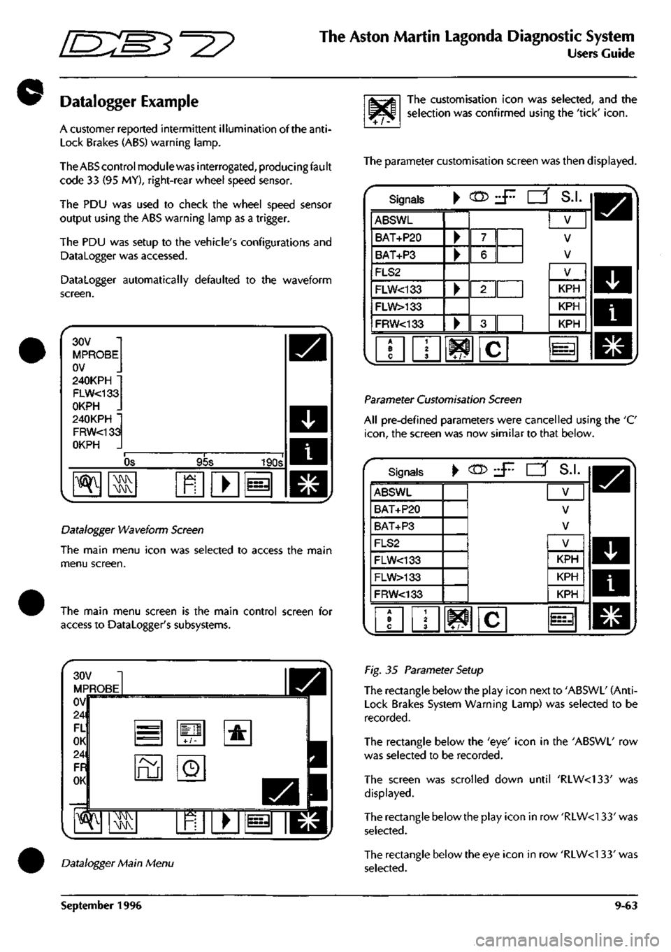
Datalogger automatically defaulted to the waveform
screen.
30V
MPROBE
OV
240KPH •
FLW<133
OKPH .
240KPH •
FRW<133
OKPH .
OS 95s 190s
^ ^ R • i=3
Datalogger Waveform Screen
The main menu icon was selected to access the main
menu screen.
The main menu screen is the main control screen for
access to Datalogger's subsystems.
^/^
The customisation icon was selected, and the
selection was confirmed using the 'tick'
icon.
The parameter customisation screen was then displayed.
Signals • c05 d^ CZf S.I.
ABSWL
BAT+P20
BAT+P3
FLS2
FLW<133
FLW>133
FRW<133
•
•
•
•
7
6
2||
3
V
V
V
1 2 3 W c
V
KPH
KPH
KPH
^=3
Parameter Customisation Screen
All pre-defined parameters were cancelled using the 'C
icon,
the screen was now similar to that below.
Signals ^ (n> •S'- rz^ S.I.
ABSWL
BAT+P20
BAT+P3
FLS2
FLW<133
FLW>133
FRW<133
V
V
V
A B C
1 2 3 ^ ^ i i C
V
KPH
KPH
KPH
Datalogger Main Menu
Fig. 35 Parameter Setup
The rectangle below the play icon next to 'ABSWl' (Anti-
lock Brakes System Warning Lamp) was selected to be
recorded.
The rectangle below the 'eye' icon in the 'ABSWl' row
was selected to be recorded.
The screen was scrolled down until 'RIW<133' was
displayed.
The rectangle below the play icon in row'RLW<133'was
selected.
The rectangle below the eye icon in row 'RLW<1 33' was
selected.
September 1996 9-63
Page 416 of 421

5'=3^
The Aston Martin Lagonda Diagnostic System
Users Guide
The 'tick' icon was selected to return to the trigger screen
which will then be as shown below.
ABSWL
Trigger
Anti-Lock Bra
^ CTD
AJUJ
^B
6V
.J7.
!•
t 1
•
S.I.
fvl
^ t
]
kes Warning Lamp
Z-.Z4
The Trigger Set-Up Screen
The 'tick' icon was then selected to return to the parameter
customisation
screen.
The screen should now look similar
to that below.
Signals • cn> J^ [Z^ S.L
RLW<133
RRW<133
BAT+P20
BAT+P3
FLS2
FLW<133
•
V
KPH
KPH
V
V
^ Kr-
i c
V
KPH
ini
Parameter Customisation - Final Setup
The 'tick' icon was pressed to access the waveform
display.
The PDU was now ready to start recording data.
The 'record' icon was selected to start recording data.
When the fault occurred, the ABS warning lamp
automatically triggered the PDU. This will place a fixed
cursor on the screen and set the time base to zero. The
PDU will stop recording after the preset record time. If no
record time has been entered, the PDU will use its default
record time of 16minutes and 40 seconds. 8m20s pre-
trigger and 8m20s post trigger.
The following figure indicates the typical waveform display
for the wheel speed sensor fault. The dotted vertical line
represents the trigger point.
16V
ABSWL
OV
240KPH "
RLW<133
OKPH .
240KPH •
RRW<133
OKPH
-55.4s
7.29s
^ 39.6s
^ MMV
\!MV
m
wheel Speed Sensor Display
September 1996 9-65