light ASTON MARTIN DB7 1997 Owner's Guide
[x] Cancel search | Manufacturer: ASTON MARTIN, Model Year: 1997, Model line: DB7, Model: ASTON MARTIN DB7 1997Pages: 421, PDF Size: 9.31 MB
Page 262 of 421
y/--^^^^3^
'—-p "^ Body and Trim
Roof Description
Volante Roof
Description
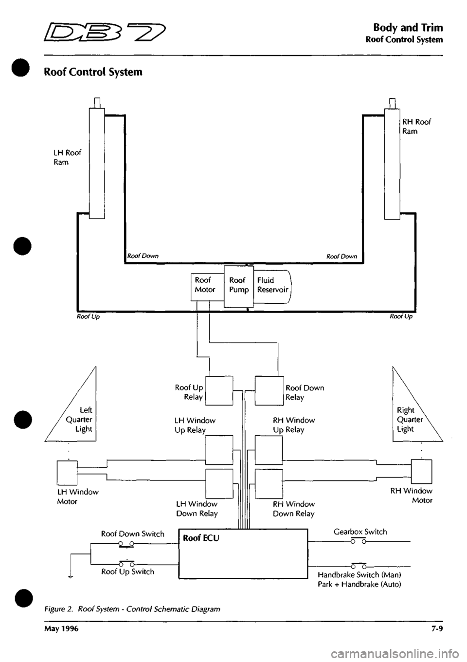
The system comprises an electrically driven hydraulic pump and two hydraulic rams for raising and lowering the
roof.
The pump is powered via two heavy duty changeover relays. Two further pairs of changeover relays power
the rear quarter windows (one pair for each window). The roof hydraulic pump is protected by a 30A fuse, the
windows by circuit breakers.
An electronic control module (ECM) is actuated by the roof switch on the centre console. The ECM controls the
operation of
both
the roof
and
rear quarter window circuits
so
that they can only be operated in
a
pre-programmed
manned.
When in operation, the ECM provides signals to the roof and to the rear quarter windows.
When the roof
switch
is moved into the open (Roof Down) position, the roof
and
rear windows move together until
approximately four seconds has elapsed. At this time, the ECM will remove power from the rear window circuits,
leaving the roof motor running. The roof motor will stop after 12 seconds (i.e. a further 8 seconds after the rear
window motors stop).
The signals will be removed from the rear window relay after 4 seconds and from the roof relay after 12 seconds
if the roof switch is held in either position for longer than 12 seconds.
In order to comply with legislation, the following features are built into the system:
If the roof switch is operated in either direction and then released before that operation is complete, the roof and
rear quarter windows will stop immediately. If, whilst the system is in operation, the ignition switch
is
turned to the
off position, the system will immediately stop.
If the roof switch is pressed again after pausing during a roof movement, the timing sequence will be as follows:
1.
If the previous direction is selected, the timing recommences from where it left off and will continue to
completion. If the ignition has been turned off, the timing will start from the beginning of its cycle.
2.
If theoppositedirection
is
selected,
the timing sequence will commence
from the beginning
of the newly selected
direction and continue to completion.
Roof and Rear Quarter Light Control
The following diagrams show the component location and the electrical control for the roof and rear quarter light
systems.
May 1996 7-7
Page 263 of 421

Body and Trim >/—^
^^^^5^
' ^ ^
Roof Components I -^' ^—^ -^-^
Roof Component Location
Roof Switch
Hydraulic Pump
ECM
Roof Up Relay
Roof Down Relay
LH Q Light Up Relay
LH Q Light Down Relay
RH Q Light Up Relay
RH Q Light Down Relay
Fuse and Circuit Breakers
Hydraulic Rams
Heated Rear Window Overide Switch
Figure 7. Roof
System
Component Location
7-8 May 1996
Page 264 of 421
5^^
Body and Trim
Roof Control System
Roof Control System
LH Roof
Ram
n
Roof Down Roof Down
n
RH Roof
Ram
Roof
Motor
Roof Up
Fluid
Reservoir I
Roof Up
Roof Up
Relay
LH Window
Up Relay
LH Window
Motor LH Window
Down Relay
Roof Down Switch
-o o-
Roof Down
Relay
RH Window
Up Relay
Right
Quarter
Light
RH Window
Down Relay
RH Window
Motor
Gearbox Switch
o~o
o o-Handbrake Switch (Man)
Park + Handbrake (Auto)
Figure 2. Roof System - Control Schematic Diagram
May 1996 7-9
Page 273 of 421
Body and Trim
Roof Seals - Adjustment
9.2.01.6 - Roof
Seals
- Adjustment
Seal adjustment is done in two stages. First stage -
lateral adjustment, and second stage - outward
adjustment. Seals are packed out using selected
packing strips.
Lateral Adjustment
Partially open the roof.
Front frame seal only: Remove the seal retaining
plate.
Remove the seal from the channel.
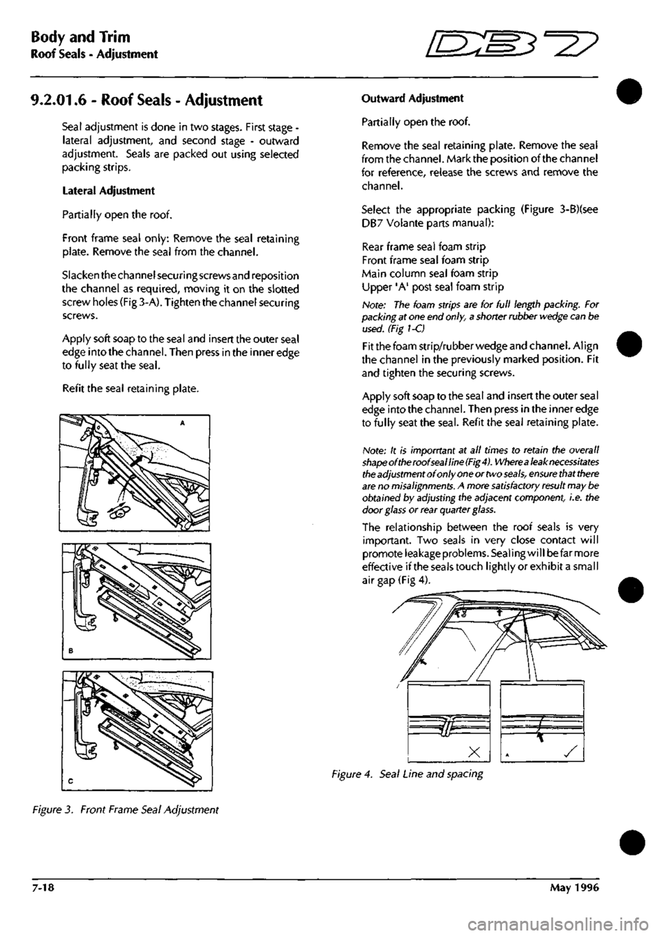
Slacken the channel securing screws and reposition
the channel as required, moving it on the slotted
screw holes (Fig 3-A). Tighten the channel securing
screws.
Apply soft soap to the seal and insert the outer seal
edge into the channel. Then press in the inner edge
to fully seat the
seal.
Refit the seal retaining plate.
Outward Adjustment
Partially open the roof.
Remove the seal retaining plate. Remove the seal
from the channel. Mark the position of the channel
for reference, release the screws and remove the
channel.
Select the appropriate packing (Figure 3-B)(see
DB7 Volante parts manual):
Rear frame seal foam strip
Front frame seal foam strip
Main column seal foam strip
Upper 'A' post seal foam strip
Note: The foam strips are for full length packing. For
packing at one end
only,
a shorter rubber
wedge
can be
used. (Fig 1-C)
Fit the foam strip/rubber wedge and channel. Align
the channel in the previously marked position. Fit
and tighten the securing screws.
Apply soft soap to the seal and insert the outer seal
edge into the channel. Then press in the inner edge
to fully seat the
seal.
Refit the seal retaining plate.
Note: It is imporrtant at all times to retain the overall
shapeoftheroofsealline(Fig4).
Wherea
leak necessitates
the
adjustment of only
one
or two
seals,
ensure
that
there
are
no
misalignments.
A more
satisfactory result
may be
obtained by adjusting the adjacent component, i.e. the
door
glass
or rear quarter glass.
The relationship between the roof seals is very
important. Two seals in very close contact will
promote leakage problems. Sealing will be far more
effective ifthe seals touch lightly or exhibit a small
air gap (Fig 4).
Figure 4. Seal Line and spacing
Figure 3. Front Frame Seal Adjustment
7-18 May 1996
Page 279 of 421
Air Conditioning
Contents '=2?
System Fault Diagnosis
Fault Finding
Blower Motor Test
Open Water Temperature Switch Needs
Short Water Temperature Switch Leads
Refrigeration
Compressors
Compressor Clutch Control
Trinary Switch
Condenser
Receiver-Drier
Evaporator
Expansion Valve
Sanden Compressor SD7H15
Manifold Gauge Set
System Checking with the Manifold Gauge Set
Evacuating the Manifold Gauge Set
Connecting the Manifold Gauge Set
Stabilising the System
Purging the Test Hoses
Leak Test
Manifold Gauge Set Check Procedures
Refrigerant Slightly Low.
Refrigerant Excessively Low.
Air In The System.
Compressor Malfunction
Moisture in the System
A Large Amount of Air in the System.
Expansion Valve Malfunction.
Expansion Valve Malfunction
Restriction in the High Pressure Side.
Torque Levels for the Hose Connections
8-30
8-33
8-33
8-33
8-34
8-35
8-35
8-35
8-35
8-36
8-36
8-36
8-37
8-39
8-39
8-39
8-39
8-40
8-40
8-41
8-41
8-42
8-42
8-43
8-44
8-45
8-45
8-46
8-46
8-47
Air Conditioning Procedures
Depressurising
Recovering Refrigerant
Evacuating and Recycling the Refrigerant
Recharging the System
Compressor Oil Check
8-47
8-47
8-48
8-49
8-49
8-2 May 1996
Page 292 of 421
Air Conditioning
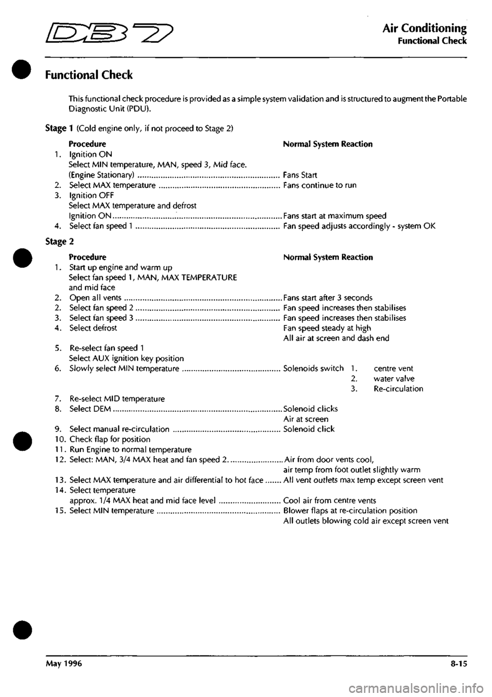
Functional Check
Functional Check
This functional check procedure is provided as a simple system validation and is structured to augment the Portable
Diagnostic Unit (PDU).
Stage 1 (Cold engine only, if not proceed to Stage 2)
Procedure Normal System Reaction
1.
Ignition ON
Select MIN temperature, MAN, speed 3, Mid face.
(Engine Stationary) Fans Start
2.
Select MAX temperature Fans continue to run
3. Ignition OFF
Select MAX temperature and defrost
Ignition ON Fans start at maximum speed
4.
Select fan speed
1
Fan speed adjusts accordingly - system OK
Stage 2
Procedure Normal System Reaction
1.
Start up engine and warm up
Select fan speed 1, MAN, MAX TEMPERATURE
and mid face
2.
Open all vents Fans start after 3 seconds
2.
Select fan speed 2 Fan speed increases then stabilises
3. Select fan speed 3 Fan speed increases then stabilises
4.
Select defrost Fan speed steady at high
All air at screen and dash end
5. Re-select fan speed 1
Select AUX ignition key position
6. Slowly select MIN temperature Solenoids switch 1. centre vent
2.
water valve
3. Re-circulation
7. Re-select MID temperature
8. Select DEM Solenoid clicks
Air at screen
9. Select manual re-circulation Solenoid click
10.
Check flap for position
11.
Run Engine to normal temperature
12.
Select: MAN, 3/4 MAX heat and fan speed 2 Air from door vents
cool,
air temp from foot outlet slightly warm
13.
Select MAX temperature and air differential to hot face All vent outlets max temp except screen vent
14.
Select temperature
approx. 1/4 MAX heat and mid face level Cool air from centre vents
15.
Select MIN temperature Blower flaps at re-circulation position
All outlets blowing cold air except screen vent
May 1996 8-15
Page 307 of 421
Air Conditioning
System Fault Diagnosis ^=2?
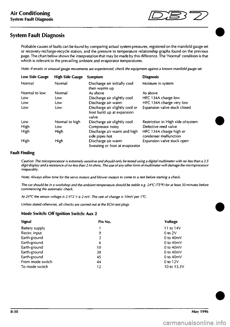
System Fault Diagnosis
Probable causes of faults can be found by comparing actual system pressures, registered on the manifold gauge set
or recovery-recharge-recycie station, and the pressure to temperature relationship graphs found on the previous
page.
The chart below shows the interpretation that may be made by this difference. The 'Normal' condition is that
which is relevant to the prevailing ambient and evaporator temperatures.
Note: If erratic or
unusual gauge movements
are experienced, check the equipment
against a
known manifold
gauge
set.
Low Side
Normal
Gauge
Normal to low
Low
Low
Low
Low
High
High
High Side Gauge
Normal
Normal
Low
Low
Low
Normal to high
Low
High
High
Fault Finding
High
Symptom
Discharge air initially cool
then warms up
As above
Discharge air slightly cool
Discharge air warm
Discharge air slightly cool or
frost build up at expansion
valve
Discharge air slightly cool
Compressor noisy
Discharge air warm and high
side pipes hot
Discharge air warm
Sweating or frost at evaporator
Diagnosis
Moisture in system
As above
HFC 134A charge low
HFC 134A charge very low
Expansion valve stuck closed
Restriction in High side of system
Defective reed valve
HFC 134A charge high or
condenser malfunction
Expansion valve stuck open
Caution:
The microprocessor is extremely sensitive
and should only
be tested
using
a
digital multimeter with no
less
than a 3.5
digit display and a
resistance
of no
less than
2 M
ohms.
The use
of any other form of multimeter will
damage the microprocessor
irreparably.
Note: Always allow time for the
servo
motors and blower motors to come to a
rest
before starting a
check.
The car should be in a workshop and the ambient
temperature
should
be
stable
e.g.
24''C
(75°F)
for at
least
30 minutes before
commencing the automatic
check.
At 24°C the
sensor
voltage is
2.972
V
± 2 mV.
The
rate of
change
is lOmVper
1
°C.
Unless
stated
otherwise,
all
checks
are carried out at the ECM
test plugs
Mode Switch: Off Ignition Switch: Aux 2
Signal Pin No.
Battery supply 1
Recirc input 9
Earth-ground 2
Earth-ground 6
Earth-ground 10
Earth-ground 38
Earth-ground 45
From mode switch 44
To mode switch 12
Voltage
n to 14v
0to2V
0 to 40mV
0 to 40mV
0 to 40mV
0 to 40mV
0 to 40mV
0 to 12V
10 to 13.3V
8-30 May 1996
Page 314 of 421
^?
Air Conditioning
Sanden Compressor SD7H15
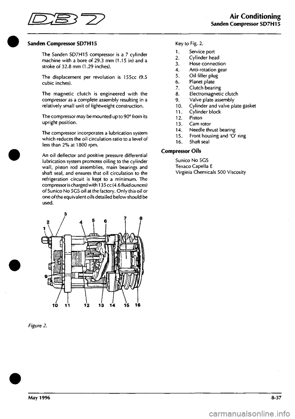
Sanden Compressor SD7H15
The Sanden SD7H15 compressor
is a 7
cylinder
machine with
a
bore
of
29.3
mm (1.15 in) and a
stroke
of
32.8
mm (1.29
inches).
The displacement
per
revolution
is
155cc
(9.5
cubic inches).
The magnetic clutch
is
engineered with
the
compressor
as a
complete assembly resulting
in a
relatively small unit
of
lightweight construction.
The compressor may be mounted up to 90° from
its
upright position.
The compressor incorporates
a
lubrication system
which reduces the
oil
circulation ratio
to a
level
of
less than
2% at 1800 rpm.
An
oil
deflector
and
positive pressure differential
lubrication system promotes oiling
to the
cylinder
wall,
piston
rod
assemblies, main bearings
and
shaft
seal,
and
ensures that
oil
circulation
to the
refrigeration circuit
is
kept
to a
minimum.
The
compressor ischarged
with!
35 cc(4.6fluid ounces)
ofSunico NoSGSoil at the factory. Only this oil
or
oneoftheequivalentoilsdetailed below should
be
used.
Key
1.
2.
3.
4.
5.
6.
7.
8.
9.
10.
11.
12.
13.
14.
15.
16.
to Fig. 2.
Service port
Cylinder head
Hose connection
Anti-rotation gear
Oil filler plug
Planet plate
Clutch bearing
Electromagnetic clutch
Valve plate assembly
Cylinder and valve plate gasket
Cylinder block
Piston
Cam rotor
Needle thrust bearing
Front housing and 'O' ring
Shaft seal
Compressor Oils
Suni
CO
No 5GS
Texaco Capella E
Virginia Chemicals 500 Viscosity
13
14 15 16
Figure
2.
May
1996
8-37
Page 318 of 421
=2?
Air Conditioning
System Checking with the Manifold Gauge Set
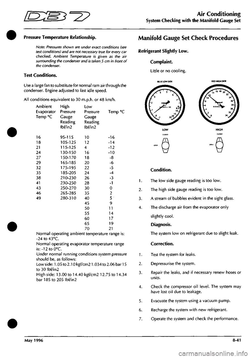
Pressure Temperature Relationship.
Note:
Pressures
shown are under exact conditions
(see
test
conditions) and
are
not
necessary
true for every
car
checked.
Ambient Temperature is given as the air
surrounding the
condenser
and
is
taken 5 cm in front of
the
condenser.
Test Conditions.
Use a large fan to substitute for normal ram air through the
condenser. Engine adjusted to fast idle speed.
All conditions equivalent to 30 m.p.h. or 48 km/h.
Ambient
Evaporator
Temp °C
16
18
21
24
27
29
32
35
38
41
43
46
49
High
Pressure
Gauge
Reading
Ibf/in2
95-115
105-125
115-125
130-150
1
50-170
165-185
175-195
185-205
210-230
230-250
250-270
265-285
280-310
Low
Pressure
Gauge
Reading
Ibf/in2
10
12
4
16
18
20
22
24
26
28
30
35
40
45
50
55
60
65
70
Ten
-16
-14
-12
-10
-8
-6
-5
-4
-3
-1
0
2
5
9
11
14
17
19
21
Normal operating ambient temperature range is:
-24 to 43°C.
Normal operating evaporator temperature range
is:-12toO°C.
Under normal running conditions system pressure
should be, as follows:
Lowside:1.05to2.10kgf/cm21.034to2.06bar15
to 30 ibf/in2
High side: 13.00 to 14.40 kgf/cm2 12.75 to 14.34
bar185to205lbf/in2
Manifold Gauge Set Check Procedures
Refrigerant Slightly Low.
Complaint.
Little or no cooling.
1.
2.
3.
4.
1.
2.
3.
4.
5.
6.
7.
BLUE LOW SIDE
KED
HIGH SIDE
Condition.
The low side gauge reading is too low.
The high side gauge reading is too low.
A stream of bubbles evident in the sight glass.
The discharge air from the evaporator only
slightly
cool.
Diagnosis.
The system low on refrigerant due to slight leak.
Correction.
Test the system for leaks.
Depressurise the system.
Repair the leaks, and if necessary renew hoses or
units.
Check the compressor oil level. The system may
have lost oil due to leakage.
Evacuate the system using a vacuum pump.
Recharge the system with new refrigerant.
Operate the system and check the performance.
May 1996 8-41
Page 319 of 421
Air Conditioning
System Checking with the Manifold Gauge Set [n::S3^^?
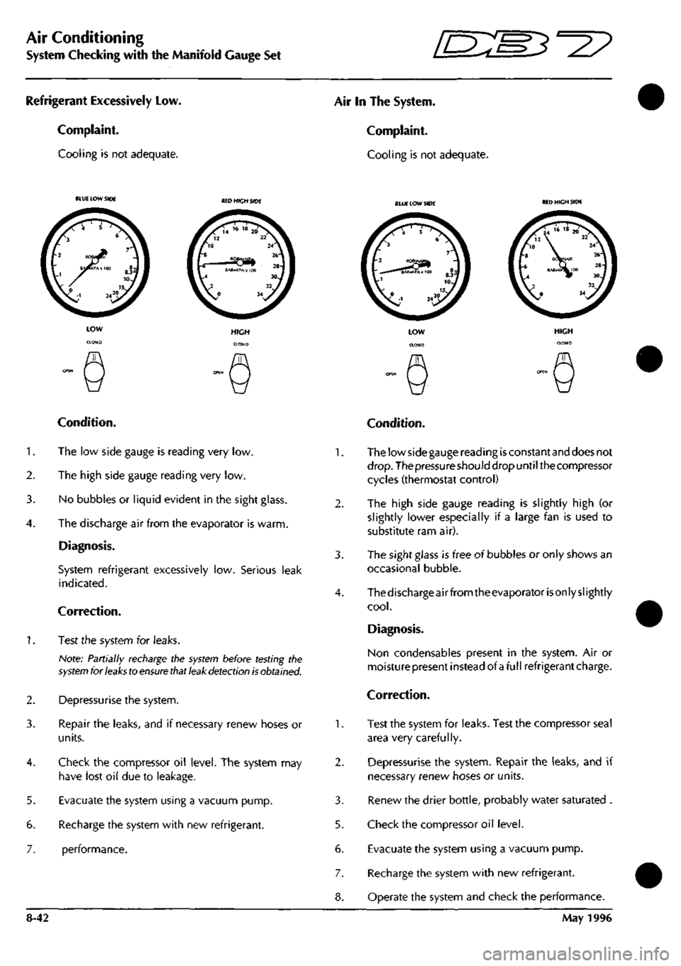
Refrigerant Excessively Low.
Complaint.
Cooling is not adequate.
Air In The System.
Complaint.
Cooling is not adequate.
BLU£ LOW SIDE SlUE LOW SIDE MD HIGH SIDE
5.
6.
7.
Condition.
1.
The low side gauge is reading very low.
2.
The high side gauge reading very low.
3. No bubbles or liquid evident in the sight glass.
4.
The discharge air from the evaporator is warm.
Diagnosis.
System refrigerant excessively low. Serious leak
indicated.
Correction.
1.
Test the system for leaks.
Note: Partially recharge the
system
before testing the
system
for
leaks
to
ensure that leak detection is
obtained.
Depressurise the system.
Repair the leaks, and if necessary renew hoses or
units.
Check the compressor oil level. The system may
have lost oil due to leakage.
Evacuate the system using a vacuum pump.
Recharge the system with new refrigerant.
performance.
2.
3.
5.
6.
7.
8-42
Condition.
The low side gauge reading
is
constant and does not
drop.
The pressure should drop until the compressor
cycles (thermostat control)
The high side gauge reading is slightly high (or
slightly lower especially if a large fan is used to
substitute ram air).
The sight glass is free of bubbles or only shows an
occasional bubble.
Thedischarge air from theevaporator
is
only slightly
cool.
Diagnosis.
Non condensables present in the system. Air or
moisturepresent instead of afullrefrigerantcharge.
Correction.
Test the system for leaks. Test the compressor seal
area very carefully.
Depressurise the system. Repair the leaks, and if
necessary renew hoses or units.
Renew the drier bottle, probably water saturated .
Check the compressor oil level.
Evacuate the system using a vacuum pump.
Recharge the system with new refrigerant.
Operate the system and check the performance.
May 1996