light ASTON MARTIN DB7 1997 Service Manual
[x] Cancel search | Manufacturer: ASTON MARTIN, Model Year: 1997, Model line: DB7, Model: ASTON MARTIN DB7 1997Pages: 421, PDF Size: 9.31 MB
Page 322 of 421
=2?
Air Conditioning
System Checking with the Manifold Gauge Set
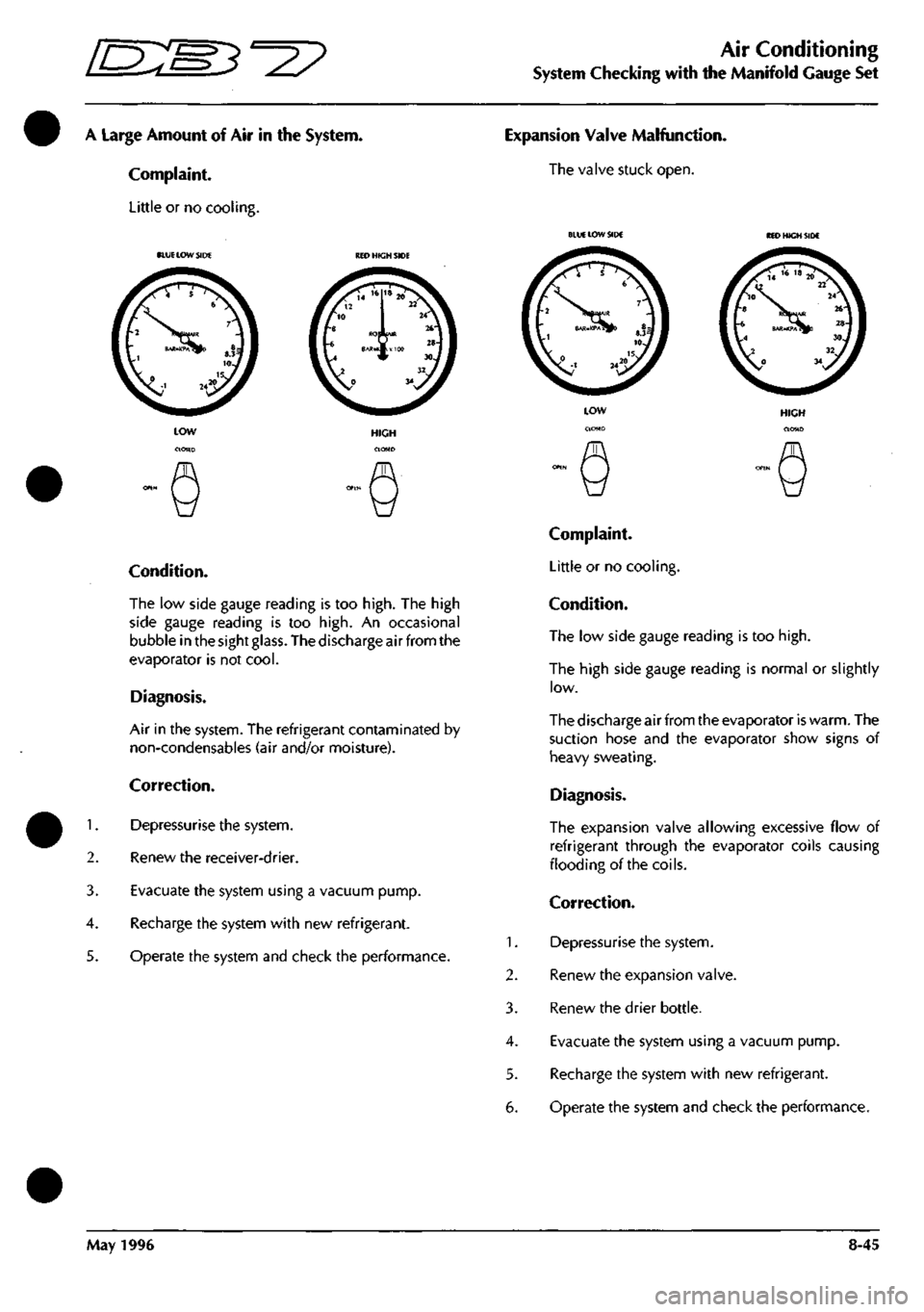
A Large Amount of Air in the System.
Complaint.
Little or no cooling.
1.
2.
3.
4.
5.
BLUE
LOW SIDE RED HIGH SIDE
Condition.
The low side gauge reading is too
high.
The high
side gauge reading is too
high.
An occasional
bubble in the sight
glass.
The discharge air from the
evaporator is not
cool.
Diagnosis.
Air in the system. The refrigerant contaminated by
non-condensables (air and/or moisture).
Correction.
Depressurise the system.
Renew the receiver-drier.
Evacuate the system using a vacuum pump.
Recharge the system with new refrigerant.
Operate the system and check the performance.
Expansion Valve Malfunction.
The valve stuck open.
1.
2.
3.
4.
5.
6.
BLUE LOW SIDE
HIGH
Complaint.
Little or no cooling.
Condition.
The low side gauge reading is too
high.
The high side gauge reading is normal or slightly
low.
The discharge air from the evaporator is warm. The
suction hose and the evaporator show signs of
heavy sweating.
Diagnosis.
The expansion valve allowing excessive flow of
refrigerant through the evaporator coils causing
flooding of the coils.
Correction.
Depressurise the system.
Renew the expansion valve.
Renew the drier bottle.
Evacuate the system using a vacuum pump.
Recharge the system with new refrigerant.
Operate the system and check the performance.
May 1996 8-45
Page 323 of 421
Air Conditioning
System Checking with the Manifold Gauge Set ^^?
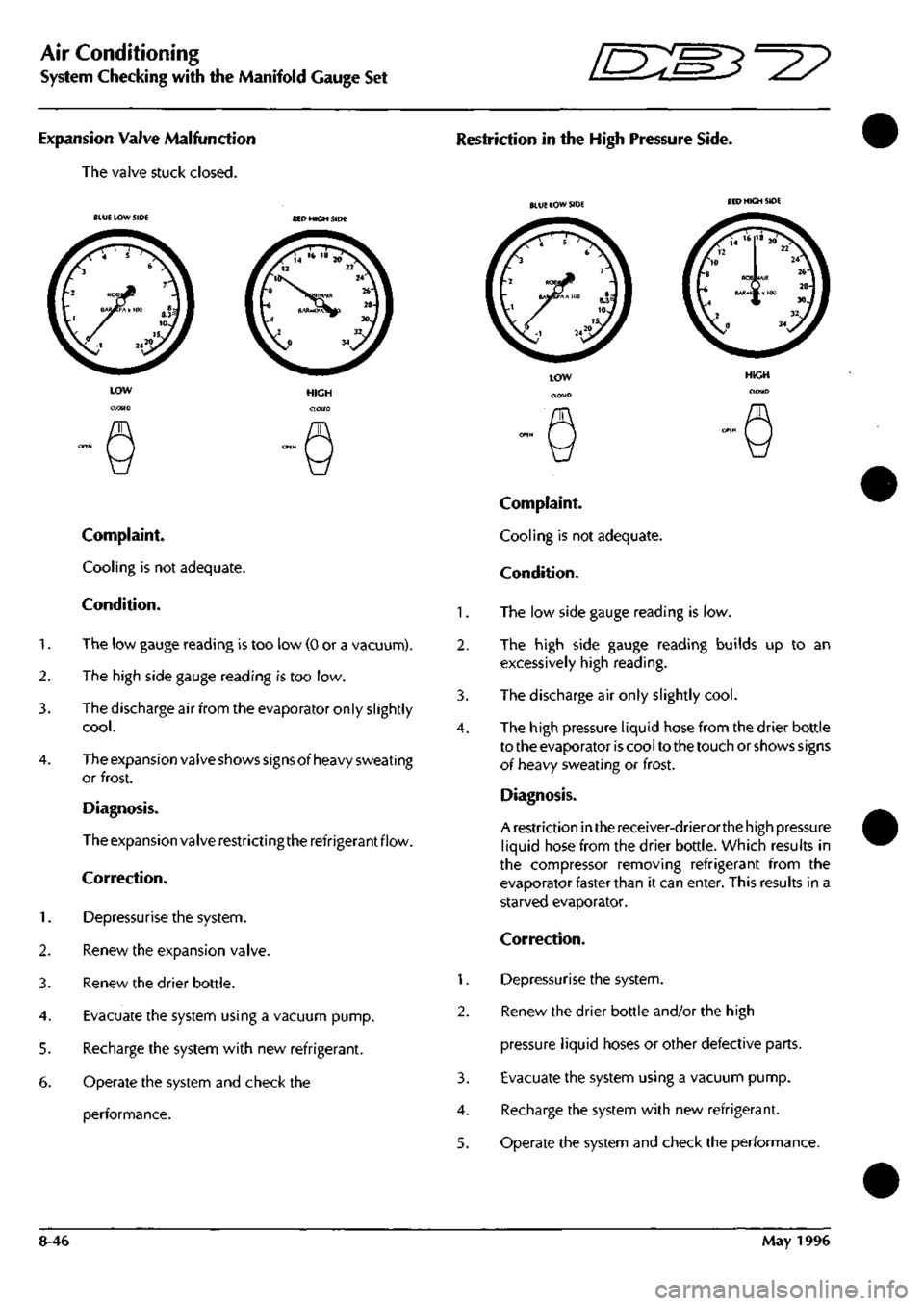
Expansion Valve Malfunction
The valve stuck closed.
Restriction in the High Pressure Side.
BLUE LOW SIDE SED HIGH SIDE
Complaint.
Cooling is not adequate.
Condition.
1.
The low gauge reading is too low (0 or a vacuunn).
2.
The high side gauge reading is too low.
3. The discharge air from the evaporator only slightly
cool.
4.
The expansion valve shows signs of heavy sweating
or frost.
Diagnosis.
The expansion valve restrictingthe refrigerant flow.
Correction.
1.
Depressurise the system.
2.
Renew the expansion valve.
3. Renew the drier bottle.
4.
Evacuate the system using a vacuum pump.
5. Recharge the system with new refrigerant.
6. Operate the system and check the
performance.
1.
2.
3.
4.
1.
2.
3.
4.
5.
BLUE LOW SIDE
Complaint.
Cooling is not adequate.
Condition.
The low side gauge reading is low.
The high side gauge reading builds up to an
excessively high reading.
The discharge air only slightly
cool.
The high pressure liquid hose from the drier bottle
to the evaporator is cool to the touch or shows signs
oi heavy sweating or frost.
Diagnosis.
A restriction in the receiver-drier orthe high pressure
liquid hose from the drier bottle. Which results in
the compressor removing refrigerant from the
evaporator faster than it can enter. This results in a
starved evaporator.
Correction.
Depressurise the system.
Renew the drier bottle and/or the high
pressure liquid hoses or other defective parts.
Evacuate the system using a vacuum pump.
Recharge the system with new refrigerant.
Operate the system and check the performance.
8-46 May 1996
Page 328 of 421
^?
Air Conditioning Repair Procedures
Compressor Removal
8.1.01.1 Compressor Removal/Renewal
Procedure
1.
Open the bonnet and fit a wing cover.
2.
Depressurise the air conditioning system.
3.
6.
7.
8.
9.
Disconnect the low and high pressure hoses from
the rear of the compressor. Plug the hose ends to
prevent the ingress of dirt.
Remove the compressor pivot bolt securing nut.
Carefully separate the muffler from the compressor
and remove and discard the 'O' ring
seal.
Fit a blanking plug to the muffler and a blanking
plate to the compressor, fit and tighten the bolt that
secures blanking plate.
Raise the vehicle to working height on a ramp.
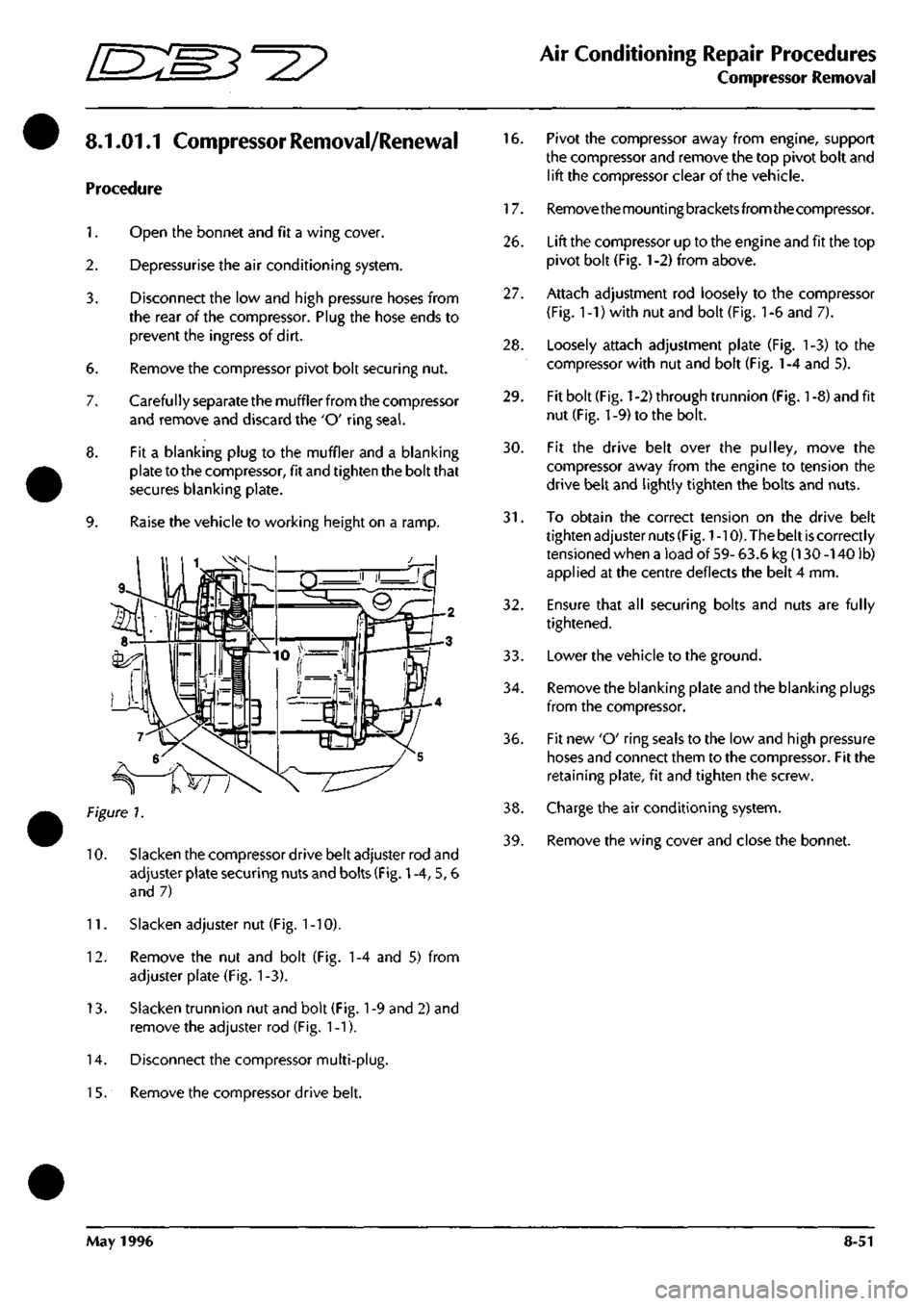
Figure 7.
10.
Slacken the compressor drive belt adjuster rod and
adjuster plate securing nuts and bolts (Fig.
1
-4, 5, 6
and 7)
11.
Slacken adjuster nut (Fig.
1
-10).
12.
Remove the nut and bolt (Fig. 1-4 and 5) from
adjuster plate (Fig. 1-3).
13.
Slacken trunnion nut and bolt (Fig.
1
-9 and 2) and
remove the adjuster rod (Fig. 1-1).
14.
Disconnect the compressor multi-plug.
1
5. Remove the compressor drive belt.
16.
Pivot the compressor away from engine, support
the compressor and remove the top pivot bolt and
lift the compressor clear of the vehicle.
17.
Removethemountingbracketsfromthecompressor.
26.
Lift the compressor up to the engine and fit the top
pivot bolt (Fig.
1
-2) from above.
27.
Attach adjustment rod loosely to the compressor
(Fig.
1
-1) with nut and bolt (Fig.
1
-6 and 7).
28.
Loosely attach adjustment plate (Fig. 1-3) to the
compressor with nut and bolt (Fig.
1
-4 and 5).
29.
Fit bolt (Fig.
1
-2) through trunnion (Fig.
1
-8) and fit
nut (Fig. 1-9) to the bolt.
30.
Fit the drive belt over the pulley, move the
compressor away from the engine to tension the
drive belt and lightly tighten the bolts and nuts.
31.
To obtain the correct tension on the drive belt
tighten adjuster nuts
(Fig.
1
-10). The belt
is
correctly
tensioned when a load of 59- 63.6 kg (130 -140 lb)
applied at the centre deflects the belt 4 mm.
32.
Ensure that all securing bolts and nuts are fully
tightened.
33.
Lowerthe vehicle to the ground.
34.
Remove the blanking plate and the blanking plugs
from the compressor.
36.
Fit new 'O' ring seals to the low and high pressure
hoses and connect them to the compressor. Fit the
retaining plate, fit and tighten the screw.
38.
Charge the air conditioning system.
39.
Remove the wing cover and close the bonnet.
May 1996 8-51
Page 353 of 421
The Aston Martin Lagonda Diagnostic System
Installation Instructions E:MB^^?
Introduction The Aston Martin Diagnostic System
This guide contains instructions for the installation
of the Portable Diagnostic Unit hardware in Aston
Martin Dealer workshops. To achieve maxinnum
benefit from the system, please follow the
instructions carefully. The following System
Diagram shows the principal system components
and panel details.
This introduction briefly describes the system and
its capabilities. This is followed by the Installation
and Power-Up procedures which give detailed
instruaions on how to start the system and access
the self-contained Interactive
Training
Programme.
The subsequent sections detail the fault diagnosis
and maintenance procedures.
WARNING:
The equipment must
only
be used by
trained
personnel.
Care should
be taken to use the
equipment in accordance with the operating
procedures.
Observe
all safety
warnings
in this
guide.
If any part of
the system is damaged do not
use it. Call your local CenRad
Service
Centre
immediately
for a
substitute
part.
Refer to
'Parts
Ordering'.
The Aston Martin Diagnostic System is a new
generation diagnostic
tool
which fulfils
a
number of
functions in aiding the technician to quickly and
accurately locate faults. The heart of the system is
the Portable Diagnostic
Unit,
a
lightweight powerful
computer/measurement system providing a step-
by-step user friendly interface for the technician.
PDU functions include:
Data Logger - The ability to monitor and record
control module signals even whilst the vehicle is
being driven.
On-Line Help-Containing detailed descriptions in
the
operation
ofthevehicleselectroniccomponents.
Vehicle Setup - The ability to setup various
adjustable parameters to their optimum settings.
Diagnostic Trouble Codes - The ability to extract
recorded fault information from the DB7's control
modules.
Each of
these
funaions is described in detail in the
PDU Users Guide.
WARNING: If
the system is used to measure high
voltages,
these voltages can appear on the pins of
other
connectors in
the
system.
Ensure
that socket
covers
are
fitted
on
unused
sockets.
Ensure
that all
connections
are
made
prior to
applying the high
voltage to
the
probes.
Do not
leave the equipment
unattended
in
this
state.
The maximum
voltage
that may be applied
between the
test
probes is 150
volts
AC or DC.
Radio Interference Statements
This digital apparatus does not exceed the Class A
limits for radio noiseemissionsfromdigital apparatus
as set
out
in
the radio interference regulations of the
Canadian Department of Communications.
This equipment has been tested and found to
comply with the limits for Class A digital device
pursuant to part 15 of the Federal Communications
Commission (FCC) rules. However, operation in
close proximity to domestic communication
equipment may cause interference. It is the
responsibility of the user to avoid or correct this
condition.
9-2 May 1996
Page 354 of 421
'=^
The Aston Martin Lagonda Diagnostic System
Installation Instructions
12 10
19 22 21 20
VIA A / /^^>^ I B T
A-XA^I'A® QA
13
16
18 29
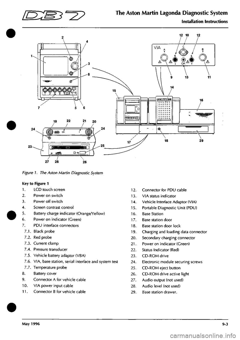
Figure 7. The Aston Martin Diagnostic System
Key to Figure 1
1.
2.
3.
4.
5.
6.
7.
7.1.
7.2.
7.3.
7.4.
7.5.
7.6.
7.7.
8.
9.
10.
11.
LCD touch screen
Power on switch
Power off switch
Screen contrast control
Battery charge indicator (Orange/Yellow)
Power on indicator (Green)
PDU interface connectors
Black probe
Red probe
Current clamp
Pressure transducer
Vehicle battery adaptor (VBA)
VIA, base station, serial interface and system test
Temperature probe
Battery cover
Connector A for vehicle cable
VIA power input cable
Connector B for vehicle cable
12.
13.
14.
15.
16.
17.
18.
19.
20.
21.
22.
23.
24.
25.
26.
27.
28.
29.
Connector for PDU cable
VIA status indicator
Vehicle Interface Adaptor (VIA)
Portable Diagnostic Unit (PDU)
Base Station
Base station door
Base station door lock
Charging and loading data connector
Secondary charging connector
Power on indicator (Green)
Status Indicator (Red)
CD-ROM drive
Electronic module securing screws
CD-ROM eject button
CD-ROM drive active light
Audio output (not used)
Audio level (not used)
Base station drawer.
May 1996 9-3
Page 355 of 421
The Aston Martin Lagonda Diagnostic System
Installation Instructions "^P
Component Identification
Base Station (Fig
1
-16)
The Base Station is a wall or bench mounted steel
unit on which up to two Portable Diagnostic Units
and a Vehicle Interface Adaptor can be stored.
Portable Diagnostic Unit (PDU) (Fig 1-15)
The PDU is a hand held diagnostic tool utilising a
touch sensitive screen and serial communications
capability
Electronics Module
The Electronics Module is located behind the base
station door (Fig
1
-17) and facilitates the charging
of the PDU battery. Also contained in the module
is
the CD-ROM drive (Fig
1
-23) for the storage of
al I
system software. The PDU must be connected to
the electronic modu le whenever it is located on the
base station.
Vehicle interface Adaptor (VIA) (Fig
1
-14)
The VIA enables the PDU to interface with vehicle
systems not equipped with serial communications.
Vehicle Battery Adaptor (VBA)
The VBA provides the correct voltage to power the
PDU from the vehicle battery and also protects the
PDU from any interference from the vehicles
electrical systems.
Controls
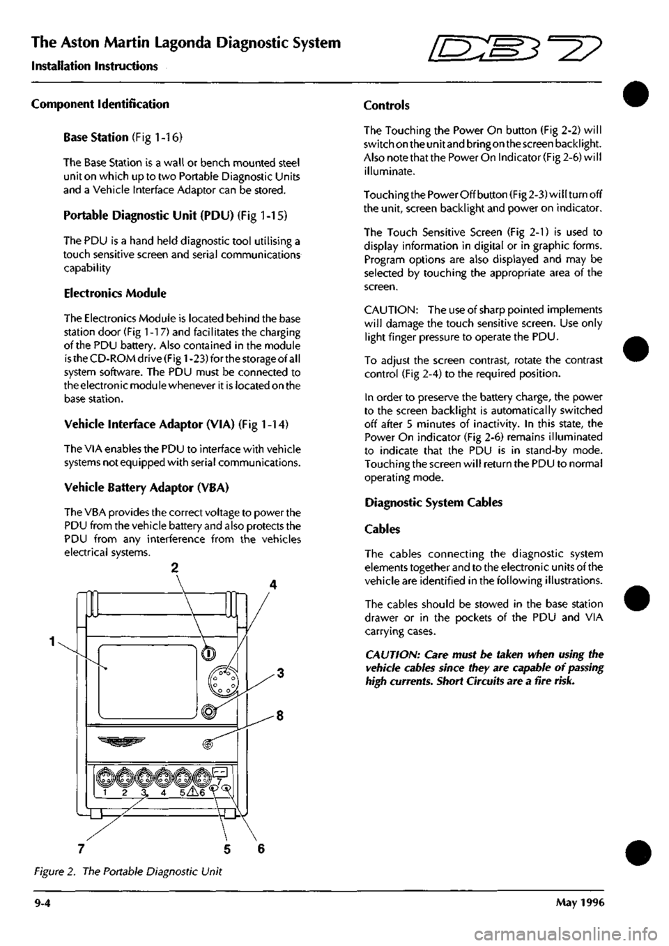
The Touching the Power On button (Fig 2-2) will
switch on the unit and bringon the screen backlight.
Also note that the Power On Indicator (Fig 2-6) will
illuminate.
Touching the Power Off button (Fig 2-3) will turn off
the unit, screen backlight and power on indicator.
The Touch Sensitive Screen (Fig 2-1) is used to
display information in digital or in graphic forms.
Program options are also displayed and may be
selected by touching the appropriate area of the
screen.
CAUTION:
The use of sharp pointed implements
will damage the touch sensitive screen. Use only
light finger pressure to operate the PDU.
To adjust the screen contrast, rotate the contrast
control (Fig 2-4) to the required position.
In order to preserve the battery charge, the power
to the screen backlight is automatically switched
off after 5 minutes of inactivity. In this state, the
Power On indicator (Fig 2-6) remains illuminated
to indicate that the PDU is in stand-by mode.
Touching the screen will return the PDU to normal
operating mode.
Diagnostic System Cables
Cables
The cables connecting the diagnostic system
elements together and to the electronic units of the
vehicle are identified in the following illustrations.
The cables should be stowed in the base station
drawer or in the pockets of the PDU and VIA
carrying cases.
CAUTION: Care must be taken when using the
vehicle cables since they are capable of
passing
high currents. Short Circuits are a fire
risk.
7 5 6
Figure 2. The Portable Diagnostic Unit
9-4 May 1996
Page 360 of 421
^^?
The Aston Martin Lagonda Diagnostic System
I nstal lation I nstructions
Bench Mounting
The base station may also be mounted on a bench, which
must be in a safe position, stable and protected form
hazards and impacts. The base station must be mounted
at the back of the bench. 'Z' clips are provided for
permanent mounting. The bench surface must be kept free
from dust at all times.
CAUTION:
A gap under the base station must be
maintained free from obstructions to allow a flow of air
under the unit for cooling.
Electronic Module installation
WARNING: The base station electronic module must be
disconnected from the mains supply prior to installation/
removal from the base station assembly. DO NOT
reconnect to the mains supply until the module is safely
fitted into the base station. This unit must be earthed.
Note:
Users in North America are advised to replace the
ceramic mains fuse in the electronic module with theglass
fuse supplied.
Procedure
1.
Unlock the base station door
2.
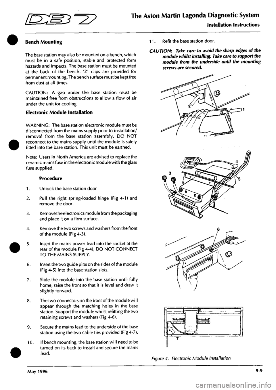
Pull the right spring-loaded hinge (Fig 4-1) and
remove the door.
3. Removetheelectronicsmodulefrom the packaging
and place it on a firm surface.
4.
Remove the two screws and washers from the front
of the module (Fig 4-3).
5. Insert the mains power lead into the socket at the
rear of the module Fig 4-4), DO NOT CONNECT
TO THE MAINS SUPPLY.
6. Insert the two guide pins on the sides of the module
(Fig 4-5) into the base station slots.
7. Slide the module into the base station until fully
home,
raise the front so that it is level and draw it
slightly forward.
8. The two connectors on the front of the module will
appear through the matching holes in the base
station.
Support the module whilst refitting the two
retaining screws and washers (Fig 4-6).
9. Secure the mains lead to the underside of the base
station using the two cable ties provided (Fig 4-7).
10.
If bench mounting, the base station will need to be
turned on its back to install and secure the mains
lead.
11.
Refit the base station door.
CAUTION: Take care to avoid the sharp edges of the
module whilst installing. Take care to support the
module from the underside until the mounting
screws are secured.
Figure 4. Electronic Module Installation
May 1996 9-9
Page 366 of 421

r^ ' ^ ^ The Aston Martin Lagonda Diagnostic System
Installation Instructions
Finishing the Test
When data analysis is finished, switch off the PDU
and disconnect it from the vehicle. Store the PDU
and cables in the carrying case and refit the case to
the base station.
Connect the PDU to the base station using cable
0064.
The base station will keep the PDU batteries
fully charged at all times (Fig 15).
Figure 15. PDU connected for recharging
Care of the Equipment
CAUTION: With the exception of those parts
referred to in the Servicing and Maintenance
section, there are no user serviceable parts. All
servicing must be carried out by GenRad Service
Centres.
Switch offthe power before cleaningtheequipment.
The Aston Martin Diagnostic System should only
be cleaned using a non-abrasive, mild cleaning
agent. Dust and other particles should be lightly
brushed from the surface before
cleaning.
Cleaning
agent should be applied to a soft lint-free cleaning
cloth and never directly to the unit. Do not soak the
cleaning cloth and take care not to allow cleaning
fluid to enter connectors.
CAUTION: Ifany liquid is spilt on theequipment,
switch off immediately.
Ensure
that the equipment
has
dried out completely before operating it again,
especially in connectors where fluid can lodge.
May 1996 9-15
Page 378 of 421
^^?
The Aston Martin Lagonda Diagnostic System
Users Guide
The Aston Martin Lagonda Diagnostic System
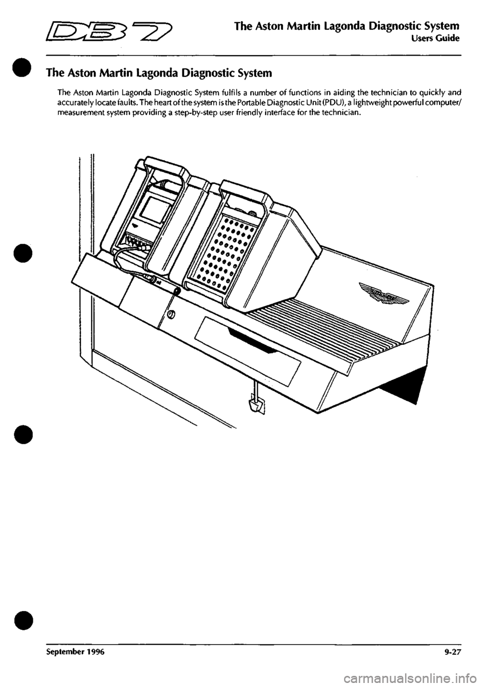
The Aston Martin Lagonda Diagnostic System fulfils a number of functions in aiding the technician to quickly and
accurately locate
faults.
The heart ofthe
system is the
Portable Diagnostic Unit
(PDU),
a
lightweight powerful computer/
measurement system providing a step-by-step user friendly interface for the technician.
September 1996 9-27
Page 379 of 421
The Aston Martin Lagonda Diagnostic System
Users Guide o: "3^^?
PDU Functions
The PDU main menu provides access into the following functions:
Diagnostics
Training
Digital Multimeter
User Self Test
Diagnostics
On selecting'Diagnostics'from the main
menu,
the user will be prompted to enter the features and market specification
of the vehicle to be tested. Use of the diagnostics in each of the above areas is described later in this guide.
Diagnostics Menu - 95 Model Year
Engine
Anti-Lock Braking System
Vlenu - 97 Model Year
Engine Diagnostics
OBD II Scan Tool
Airbag
Seat Belt Pretensioner
•
•
•
•
Transmission
Engine Datalogger
Climate Control
PATS System
Climate Control
Transmission
Anti-Lock Braking System
Security
Digital Multimeter
The Digital Multimeter function provides the capabilityto measure voltage, current, resistance, frequency, pulse width,
pulse period, and duty cycle. These measurements are usually made using the PDU measurement probes. Measurements
may also be made using the module pin selection function on the Teves Mk
II
braking system and on the Air Conditioning
system.
Training
An on-screen programme is provided to train new users in the use of screen icons and in the use of the digital multi
meter and datalogger functions.
User Self Test
In order to prove that the equpment is functioning correctly, a complete user self test is incorporated. The user is directed
to test the PDU and then to progressively connect each part of the PDU system which will be tested by the software.
Any fault identified during the test is notified to the user. If no faults are identified, the user is advised on the correct
functioning of the system.
PDU Power
Power for the PDU is supplied via an internal rechargeable battery pack which can keep the PDU operational for
approximately one hour when disconnected from the base station and the vehicle. In order to preserve PDU battery
charge, power to the screen backlight is automatically cut after five minutes of inactivity. The power ON indicator
remains lit, indicating that the PDU is in 'stand-by' mode. One touch of the screen will restore backlight power.
When connected to the base station, power is supplied to the PDU from the Electronic Module to recharge the PDU
battery pack as necessary.
On 95 MY vehicles, the Vehicle Battery Adaptor (VBA) is used to maintain PDU power.
On 97 MY vehicles, when connected via the MPA to either diagnostic socket on the vehicle, power is supplied via pin
4 (chassis ground) and pin 16 (battery power) to maintain PDU power at all times even when the vehicle ignition is
switched off.
On all model years, when connected to the air conditioning system using the VIA, the vehicle battery adaptor (VBA)
must also be used to maintain PDU power.
9-28 September 1996