battery ASTON MARTIN DB7 1997 Repair Manual
[x] Cancel search | Manufacturer: ASTON MARTIN, Model Year: 1997, Model line: DB7, Model: ASTON MARTIN DB7 1997Pages: 421, PDF Size: 9.31 MB
Page 343 of 421
Air Conditioning
Portable Diagnostic Unit - Signal Monitoring 3^^?
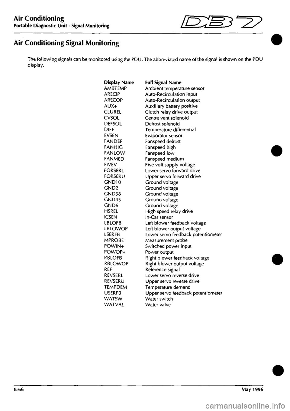
Air Conditioning Signal Monitoring
The following signals can be monitored using the PDU. The abbreviated name of the signal is shown on the PDU
display.
Display Name Full Signal Name
AMBTEMP Ambient temperature sensor
ARECIP Auto-Recirculation input
ARECOP Auto-Recirculation output
AUX+ Auxiliary battery positive
CLUREL Clutch relay drive output
CVSOL Centre vent solenoid
DEFSOL Defrost solenoid
DIFF Temperature differential
EVSEN Evaporator sensor
FANDEF Fanspeed defrost
FANHIG Fanspeed high
FAN LOW Fanspeed low
FANMED Fanspeed medium
FIVEV Five volt supply voltage
FORSERL Lower servo forward drive
FORSERU Upper servo forward drive
GND10 Ground voltage
GND2 Ground voltage
GND38 Ground voltage
GND45 Ground voltage
GND6 Ground voltage
HSREL High speed relay drive
ICSEN In-Car sensor
LBLOFB Left blower feedback voltage
LBLOWOP Left blower output voltage
LSERFB Lower servo feedback potentiometer
MPROBE Measurement probe
POWIN+ Switched power input
POWOP+ Power output
RBLOFB Right blower feedback voltage
RBLOWOP Right blower output voltage
REF Reference signal
REVSERL Lower servo reverse drive
REVSERU Upper servo reverse drive
TEMPDEM Temperature demand
USERFB Upper servo feedback potentiometer
WATSW Water switch
WATVAL Water valve
8-66 May 1996
Page 344 of 421
^=2?
Air Conditioning
Portable Diagnostic Unit - Signal Definitions
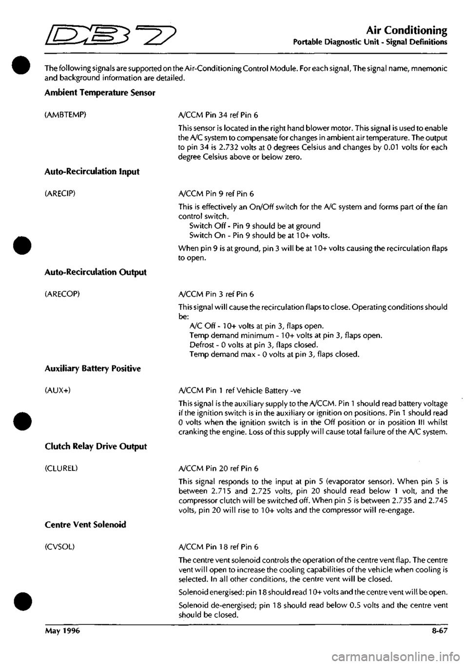
ThefollowingsignalsaresupportedontheAir-ConditioningControlModule. For each signal. The signal name, mnemonic
and background information are detailed.
Ambient Temperature Sensor
(AMBTEMP)
Auto-Recircuiation Input
(ARECIP)
Auto-Recirculation Output
(ARECOP)
Auxiliary Battery Positive
(AUX+)
Clutch Relay Drive Output
(CLUREL)
A/CCM Pin 34 ref Pin 6
This sensor is located in the right hand blower motor. This signal is used to enable
the A/C system to compensate for changes in ambient air temperature. The output
to pin 34 is 2.732 volts at 0 degrees Celsius and changes by 0.01 volts for each
degree Celsius above or below zero.
A/CCM Pin 9 ref Pin 6
This is effectively an On/Off switch for the A/C system and forms part of the fan
control switch.
Switch Off - Pin 9 should be at ground
Switch On - Pin 9 should be at 10+ volts.
When pin 9 is at ground, pin 3 will be at 10+ volts causing the recirculation flaps
to open.
A/CCM Pin 3 ref Pin 6
This signal will cause the recirculation flaps to close. Operating conditions should
be:
A/C Off - 10+ volts at pin 3, flaps open.
Temp demand minimum - 10+ volts at pin 3, flaps open.
Defrost - 0 volts at pin 3, flaps closed.
Temp demand max - 0 volts at pin 3, flaps closed.
A/CCM Pin 1 ref Vehicle Battery -ve
This signal istheauxiliary supply to the A/CCM. Pin
1
should read battery voltage
if the ignition switch is in the auxiliary or ignition on positions. Pin
1
should read
0 volts when the ignition switch is in the Off position or in position III whilst
cranking the engine. Loss of this supply will cause total failureof the A/C system.
A/CCM Pin 20 ref Pin 6
This signal responds to the input at pin 5 (evaporator sensor). When pin 5 is
between 2.715 and 2.725 volts, pin 20 should read below 1 volt, and the
compressor clutch will be switched off. When pin 5 is between 2.735 and 2.745
volts,
pin 20 will rise to 10+ volts and the compressor will re-engage.
Centre Vent Solenoid
(CVSOL) A/CCM Pin 18 ref Pin 6
The centre vent solenoid controls the operation of the centre vent flap. The centre
vent will open to increase the cooling capabilities of the vehicle when cooling is
selected.
In all other conditions, the centre vent will be closed.
Solenoid energised: pin 18 should read 10+volts and the centre vent will be open.
Solenoid de-energised; pin 18 should read below 0.5 volts and the centre vent
should be closed.
May 1996 8-67
Page 347 of 421
Air Conditioning
Portable Diagnostic Unit - Signal Definitions ^^P
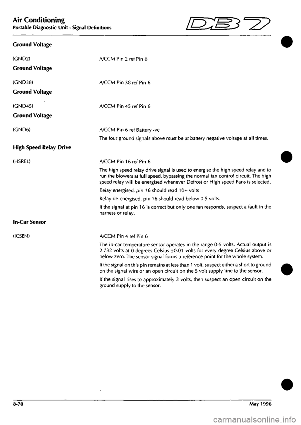
Ground Voltage
(GND2)
Ground Voltage
(GND38)
Ground Voltage
(GND45)
Ground Voltage
(GND6)
High Speed Relay Drive
(HSREL)
In-Car Sensor
(ICSEN)
A/CCMPin2refPin6
A/CCM Pin 38 ref Pin 6
A/CCM Pin 45 ref Pin 6
A/CCM Pin 6 ref Battery -ve
The four ground signals above must be at battery negative voltage at all times.
A/CCM Pin 16 ref Pin 6
The high speed relay drive signal is used to energise the high speed relay and to
run the blowers at full speed, bypassing the normal fan control circuit. The high
speed relay will be energised whenever Defrost or High speed Fans is selected.
Relay energised, pin 16 should read 10+ volts
Relay de-energised, pin 16 should read below 0.5 volts.
If the signal at pin 16 is correct but only one fan responds, suspect a fault in the
harness or relay.
A/CCM Pin 4 ref Pin 6
The in-car temperature sensor operates in the range 0-5 volts. Actual output is
2.732 volts at 0 degrees Celsius ±0.01 volts for every degree Celsius above or
below zero. The sensor signal forms a reference point for the whole system.
If the signal on this pin remains at less than
1
volt, suspect either a short to ground
on the signal wire or an open circuit on the 5 volt supply line to the sensor.
If the signal rises to approximately 3 volts, then suspect an open circuit on the
ground supply to the sensor.
8-70 May 1996
Page 349 of 421
Air Conditioning
Portable Diagnostic Unit Signal Definitions ~3^^?
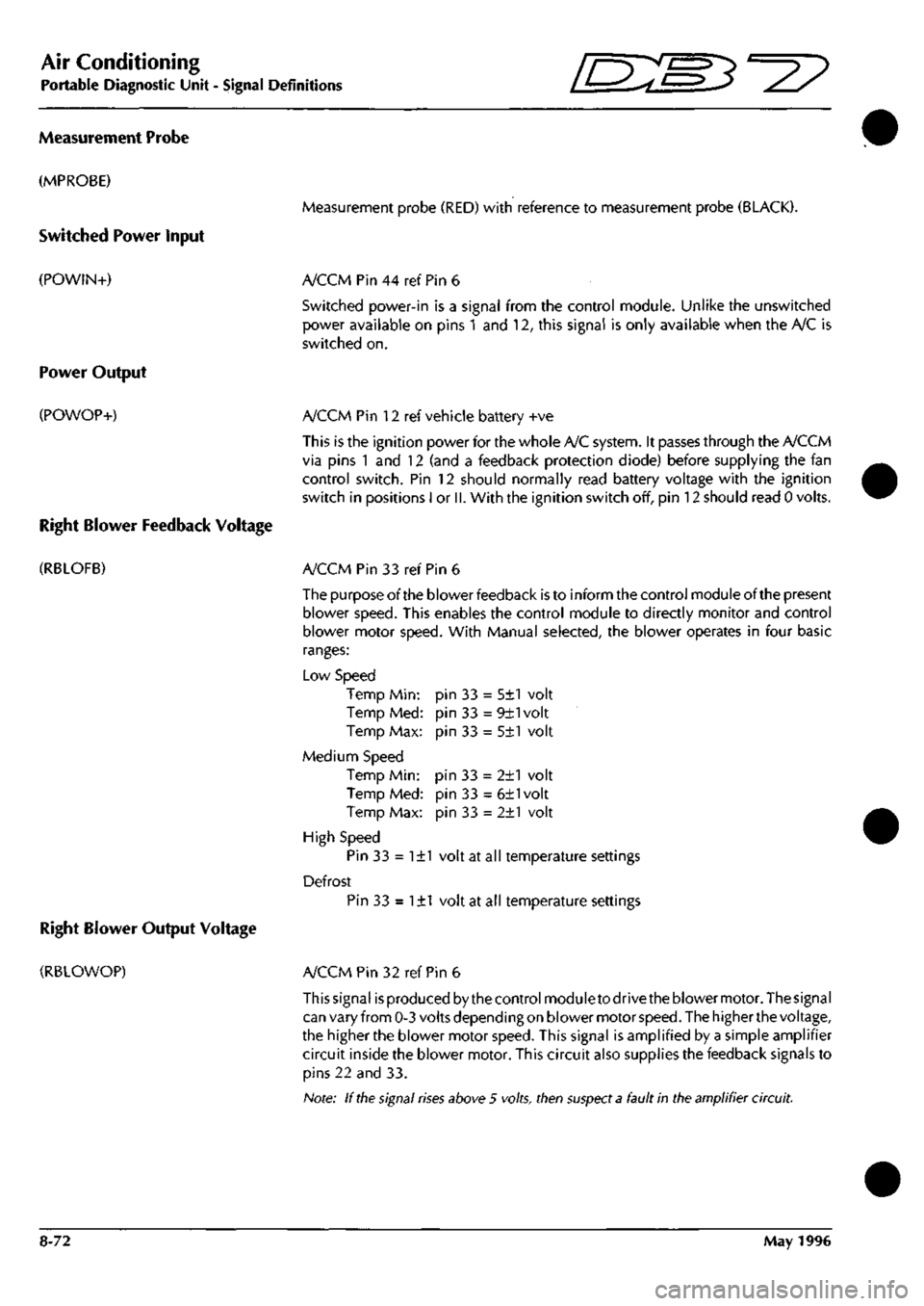
Measurement Probe
(MPROBE)
Switched Power Input
(POWIN+)
Power Output
(POWOP+)
Right Blower Feedback Voltage
(RBLOFB)
Right Blower Output Voltage
(RBLOWOP)
Measurement probe (RED) with reference to measurement probe (BLACK).
A/CCM Pin 44 ref Pin 6
Switched power-in is a signal from the control module. Unlike the unswitched
power available on pins 1 and 12, this signal is only available when the A/C is
switched on.
A/CCM Pin 12 ref vehicle battery +ve
This is the ignition power for the whole A/C system. It passes through the A/CCM
via pins 1 and 12 (and a feedback protection diode) before supplying the fan
control switch. Pin 12 should normally read battery voltage with the ignition
switch in positions I or
II.
With the ignition switch off, pin 12 should read 0 volts.
A/CCM Pin 33 ref Pin 6
The purpose of the blower feedback is to inform the control module of the present
blower speed. This enables the control module to directly monitor and control
blower motor speed. With Manual selected, the blower operates in four basic
ranges:
Low Speed
Temp Min:
Temp Med:
Temp Max:
Medium Speed
Temp Min:
Temp Med:
Temp Max:
High Speed
Pin 33 = 1±1 volt at all temperature settings
Defrost
Pin 33 = 1±1 volt at all temperature settings
pin 33 = 5±1 volt
pin 33 = 9±1volt
pin 33 = 5±1 volt
pin 33 = 2±1 volt
pin 33 = 6±1volt
pin 33 = 2±1 volt
A/CCM Pin 32 ref Pin 6
This signal is produced by the control module to drive the blower motor. The signal
can vary from 0-3 volts depending on blower motor
speed.
The higher the voltage,
the higher the blower motor speed. This signal is amplified by a simple amplifier
circuit inside the blower motor. This circuit also supplies the feedback signals to
pins 22 and 33.
Note: If
the
signal
rises
above 5 volts, then
suspect a
fault in the amplifier circuit.
8-72 May 1996
Page 354 of 421
'=^
The Aston Martin Lagonda Diagnostic System
Installation Instructions
12 10
19 22 21 20
VIA A / /^^>^ I B T
A-XA^I'A® QA
13
16
18 29
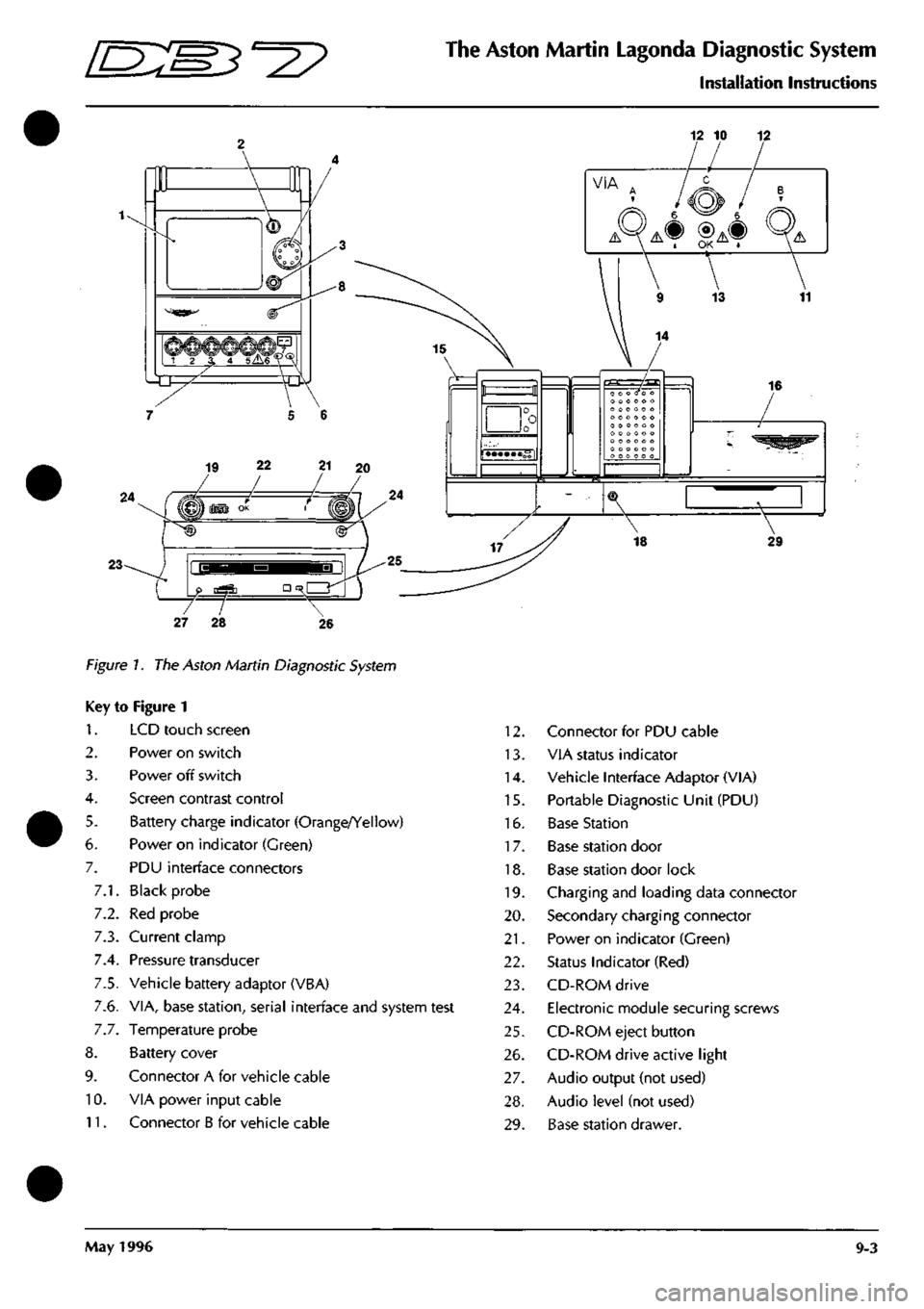
Figure 7. The Aston Martin Diagnostic System
Key to Figure 1
1.
2.
3.
4.
5.
6.
7.
7.1.
7.2.
7.3.
7.4.
7.5.
7.6.
7.7.
8.
9.
10.
11.
LCD touch screen
Power on switch
Power off switch
Screen contrast control
Battery charge indicator (Orange/Yellow)
Power on indicator (Green)
PDU interface connectors
Black probe
Red probe
Current clamp
Pressure transducer
Vehicle battery adaptor (VBA)
VIA, base station, serial interface and system test
Temperature probe
Battery cover
Connector A for vehicle cable
VIA power input cable
Connector B for vehicle cable
12.
13.
14.
15.
16.
17.
18.
19.
20.
21.
22.
23.
24.
25.
26.
27.
28.
29.
Connector for PDU cable
VIA status indicator
Vehicle Interface Adaptor (VIA)
Portable Diagnostic Unit (PDU)
Base Station
Base station door
Base station door lock
Charging and loading data connector
Secondary charging connector
Power on indicator (Green)
Status Indicator (Red)
CD-ROM drive
Electronic module securing screws
CD-ROM eject button
CD-ROM drive active light
Audio output (not used)
Audio level (not used)
Base station drawer.
May 1996 9-3
Page 355 of 421
The Aston Martin Lagonda Diagnostic System
Installation Instructions "^P
Component Identification
Base Station (Fig
1
-16)
The Base Station is a wall or bench mounted steel
unit on which up to two Portable Diagnostic Units
and a Vehicle Interface Adaptor can be stored.
Portable Diagnostic Unit (PDU) (Fig 1-15)
The PDU is a hand held diagnostic tool utilising a
touch sensitive screen and serial communications
capability
Electronics Module
The Electronics Module is located behind the base
station door (Fig
1
-17) and facilitates the charging
of the PDU battery. Also contained in the module
is
the CD-ROM drive (Fig
1
-23) for the storage of
al I
system software. The PDU must be connected to
the electronic modu le whenever it is located on the
base station.
Vehicle interface Adaptor (VIA) (Fig
1
-14)
The VIA enables the PDU to interface with vehicle
systems not equipped with serial communications.
Vehicle Battery Adaptor (VBA)
The VBA provides the correct voltage to power the
PDU from the vehicle battery and also protects the
PDU from any interference from the vehicles
electrical systems.
Controls
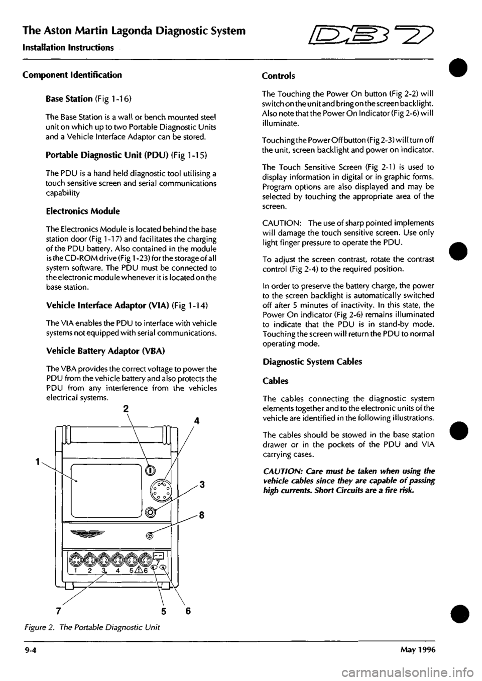
The Touching the Power On button (Fig 2-2) will
switch on the unit and bringon the screen backlight.
Also note that the Power On Indicator (Fig 2-6) will
illuminate.
Touching the Power Off button (Fig 2-3) will turn off
the unit, screen backlight and power on indicator.
The Touch Sensitive Screen (Fig 2-1) is used to
display information in digital or in graphic forms.
Program options are also displayed and may be
selected by touching the appropriate area of the
screen.
CAUTION:
The use of sharp pointed implements
will damage the touch sensitive screen. Use only
light finger pressure to operate the PDU.
To adjust the screen contrast, rotate the contrast
control (Fig 2-4) to the required position.
In order to preserve the battery charge, the power
to the screen backlight is automatically switched
off after 5 minutes of inactivity. In this state, the
Power On indicator (Fig 2-6) remains illuminated
to indicate that the PDU is in stand-by mode.
Touching the screen will return the PDU to normal
operating mode.
Diagnostic System Cables
Cables
The cables connecting the diagnostic system
elements together and to the electronic units of the
vehicle are identified in the following illustrations.
The cables should be stowed in the base station
drawer or in the pockets of the PDU and VIA
carrying cases.
CAUTION: Care must be taken when using the
vehicle cables since they are capable of
passing
high currents. Short Circuits are a fire
risk.
7 5 6
Figure 2. The Portable Diagnostic Unit
9-4 May 1996
Page 357 of 421

The Aston Martin Lagonda Diagnostic System
Installation Instructions mm^^?
Diagnostic System Cables
311
^ri M
r 1
3130-0030-01 VIA-PDU Cable
^
ctfa
3130-0778-00-B Anti-Lock Brakes
3130-0064-01 Base Station-PDU Cable
3130-0475-00 Test Probes
VBA
3130-0024-01 Vehicle Battery Adapti
3130-0764-00 Road Test Ext Cable
9-6 May 1996
Page 361 of 421
The Aston Martin Lagonda Diagnostic System
Installation Instructions
[ES^'^?
Powering-Up the Base Station
When first operating the System or when first using
a PDU fitted with substitute batteries, it will take up
to36 hourstoachievefull charge. Inthemeantime,
the PDU can be used whilst connected to the base
station or to the vehicle battery.
Vi/\RNmGS:
When using the system equipment, basic safety
precautions should always be followed, including:
Carefully read and follow all instructions.
Care should be taken as burns can occur from
touching hot parts.
Do not operate the appliance with a damaged
mains lead or if the appliance has been dropped or
damaged. Call your local GenRad Service Centre
immediately for a substitute
part.
Do not let the mains lead hang over the
edge
of the
table, bench or counter or come into contact with
hot manifolds or moving fan blades.
The Aston Martin Portable Diagnostic Unit
is
fitted with an
auto switching power supply suitable for voltage supplies
of 100 - 240 VAC 50 - 60 Hz. You need only check that
the power cord connector is of the correct type for your
power outlets.
1.
Connect the mains lead to the mains outlet.
2.
Check that the green indicator lamp above the base
station door is illuminated. If the green lamp does
not come on, see the problem solving section for
advice.
3. After a few seconds, during which the electronics
module completes its self-test, the red OK indicator
lamp should illuminate. If the red lamp does not
come on, see the problem solving section for
advice.
4.
Allow the base station electronics module to reach
working temperature. This will take approximately
BOminutes, after which time the base station will be
ready to accept the software on CD-ROM.
5. Slide the PDU into its carrying case and place the
associated cables and probes in the carrying case
compartments.
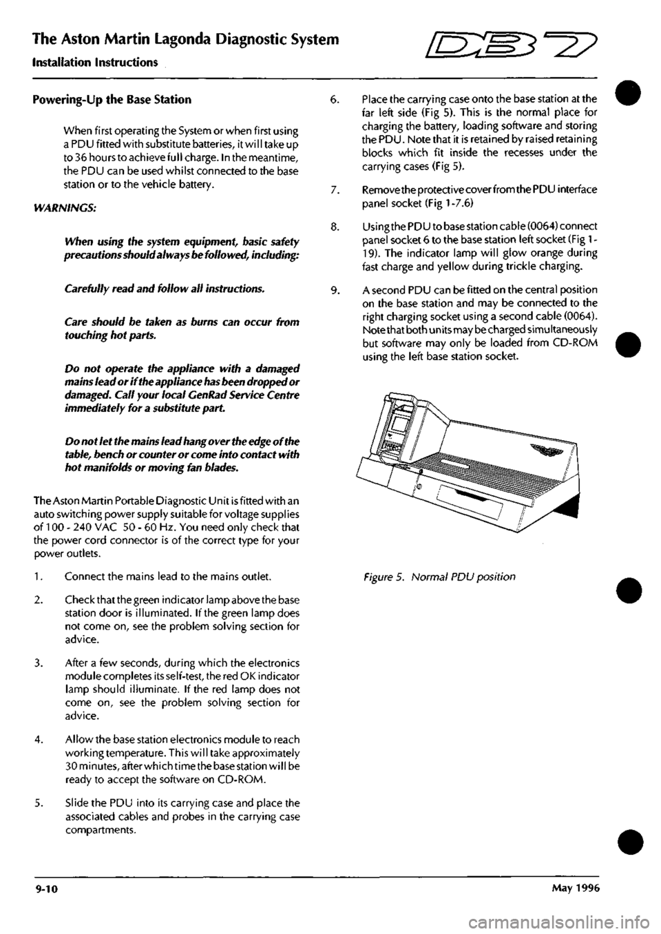
6. Place the carrying case onto the base station at the
far left side (Fig 5). This is the normal place for
charging the battery, loading software and storing
the PDU. Note that it is retained by raised retaining
blocks which fit inside the recesses under the
carrying cases (Fig 5).
7. Remove the protective coverfromthe PDU interface
panel socket (Fig
1
-7.6)
8. Usingthe PDU to base station cable (0064) connect
panel socket 6 to the base station left socket (Fig
1
-
19).
The indicator lamp will glow orange during
fast charge and yellow during trickle charging.
9. A second PDU can be fitted on the central position
on the base station and may be connected to the
right charging socket using a second cable (0064).
Note that both units may be charged simultaneously
but software may only be loaded from CD-ROM
using the left base station socket.
Figure 5. Normal PDU position
9-10 May 1996
Page 365 of 421
The Aston Martin Lagonda Diagnostic System
Installation Instructions 5^27
Battery Charging
The PDU is fitted with internal NICAD batteries
which allow the PDU to be transported whilst
retaining programs. The batteries are not designed
to be used as a general power source. A special
circuit monitorstheamountofcharge in the batteries
so that they cannot be overcharged.
From the time when first operating the system or a
PDU fitted with substitute batteries, it will take up
to 36 hours to achieve full charge. In the meantime,
the PDU can be used whilst connected to the base
station or to the vehicle battery. Keep transit times
to and from the vehicle as short as reasonably
possible to preserve battery charge.
Subsequent battery charges
shou Id
take six to seven
hours from fully discharged. The PDU must always
be left connected to the base station when not in
use in order to keep the batteries fully charged.
CAUTION: The rechargeable NICAD batteries
fitted to the PDU are of a special type and must
only be replaced with GenRad approved parts. Do
not substitute the batteries with any other type.
Always
dispose
of old batteries in compliance with
local recycling regulations. The procedure for
changing the battery pack
is
described later in this
installation guide.
Operating Procedures
Refer to the Aston Martin Diagnostic System Users
Guide for detail on each of the PDU software
options
Selecting Diagnostics
1.
Switch on the PDU, the main menu will be
displayed.
2.
Select 'Run Diagnostic' from the main menu and
confirm the selection by pressing the 'tick'
icon.
A
sequence of menus will be displayed requesting
identification of the vehicle under test.
3. The system will load the appropriate software.
4.
On completion of software loading, disconnect the
PDU from the base station and transfer it in its
carrying case to the vehicle. The additional pockets
in the carrying case may be used for carrying any
interface cables required.
5. If the VIA is required, also transfer it in its carrying
case to the vehicle together with any vehicle
interface cable required.
Using the PDU on the Vehicle
At the vehicle, the PDU may be removed from its
carrying case if required. The PDU should always
be connected to the vehicle using the Vehicle
Battery Adaptor (VBA) (0024). The PDU will
continue to charge from the vehicle battery.
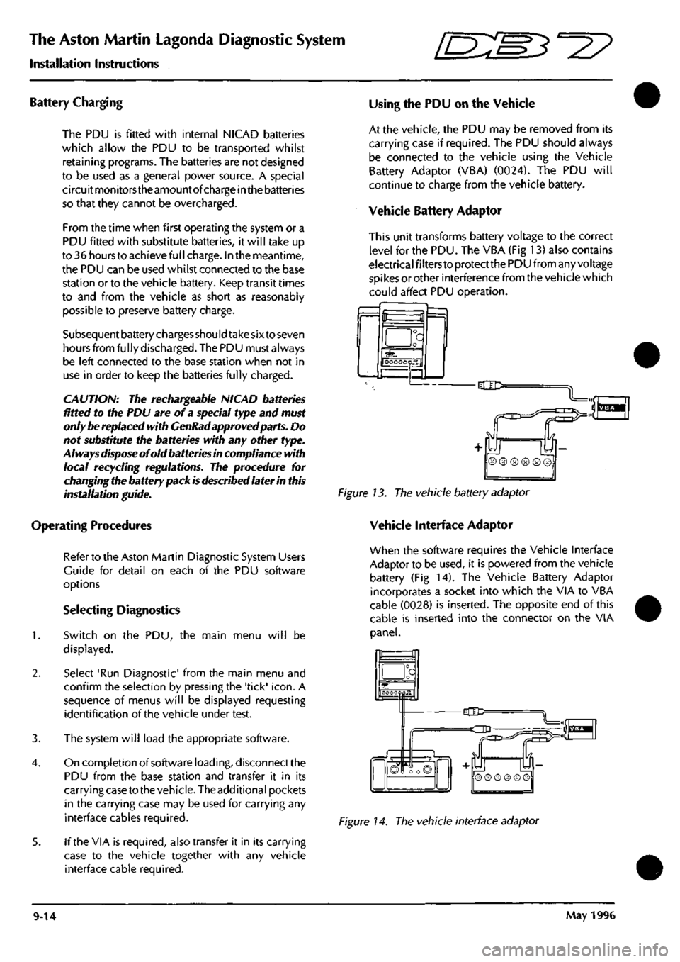
Vehicle Battery Adaptor
This unit transforms battery voltage to the correct
level for the PDU. The VBA (Fig 13) also contains
electrical filters to protect the PDU from any voltage
spikes or other interference from the vehicle which
could affect PDU operation.
f=l
a
OOOOOQS.fl
-dlD:
Figure 13. The vehicle battery adaptor
Vehicle Interface Adaptor
When the software requires the Vehicle Interface
Adaptor to be used, it is powered from the vehicle
battery (Fig 14). The Vehicle Battery Adaptor
incorporates a socket into which the VIA to VBA
cable (0028) is inserted. The opposite end of this
cable is inserted into the connector on the VIA
panel.
_a
hOOOOQpH"
-CIC=
=dD
n
S
© ® ® ® © ©
Figure 14. The vehicle interface adaptor
9-14 May 1996
Page 368 of 421
^^?
The Aston Martin Lagonda Diagnostic System
Installation Instructions
Step 4
Connect the mains power to the base station. Is the base station red indicator illuminated?
YES - Go to step 5
NO - Renew the electronic module (0019)
Steps
Switch off the PDU and disconnect
al I
cables. Set up the PDU to charge from the left charge socket on the base station
using one of the PDU to base station cables. Is the PDU charge indicator (Fig 1-5) illuminated.
YES - Go to step 9
NO - Go to step 6
Step 6
Set up the PDU to charge from the right socket on the base station using the same PDU to base station cable. Is the
PDU charge indicator (Fig 1-5) illuminated.
YES - Co to step 8
NO - Go to step 7
Step 7
Using the VBA, connect the PDU to a charged vehicle battery. Is the PDU charge indicator illuminated?
YES - Go to step 8
NO - Renew the PDU (001 7)
Steps
Switch off the PDU and disconnect all cables. Connect the PDU to the base station left connector using the second
PDU to base station cable (0064). Is the PDU charge indicator illuminated?
YES - The first PDU to base station cable (0064) is faulty, renew the cable.
NO - Renew the electronic module (0019).
Step 9
Switch on the PDU. Is the PDU power indicator (Fig 1-6) illuminated?
YES - Go to step 10.
NO - Renew the PDU (001 7).
Step 10
Is the PDU touch screen illuminated?
YES - Go to step 12.
NO - Go to step 11.
May 1996 9-17