battery ASTON MARTIN DB7 1997 User Guide
[x] Cancel search | Manufacturer: ASTON MARTIN, Model Year: 1997, Model line: DB7, Model: ASTON MARTIN DB7 1997Pages: 421, PDF Size: 9.31 MB
Page 136 of 421
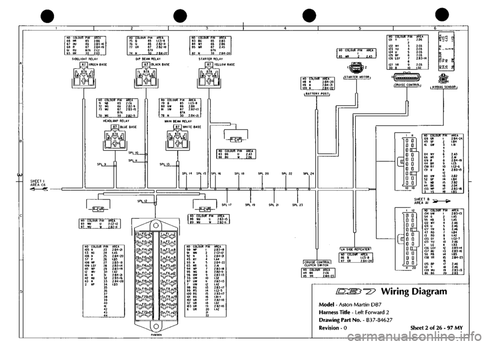
NO 66 67 68 61 6I>
COLOUR
NR NU R RU NR
PIN RS 86 87 8« 30
AREA 2.B6
2.B3-I6
2.B4-I9
2.C2 2.D3
NO 75 76 77
74
COLOUR
B U UR
N
PIN 85 86
87 87A
30
AREA
1.03-8
2.82-11
2.B2-I0
2.B4-22
NO 83 M 85
82
COLOUR
8G wr WR
N
PIN B5 86
87 B7A
30
AREA 2.B3 2.86 2.A5
2.84-20
SIDELIGHT RELAY I
87
{GREEN BASE
JqpL L 87A
DW|
OlP BEAM RELAY I 87 I BLACK BASE
87A
'5^BI
lO
SHEET I AREA C6 <4 «
mu
STARTER RELAY I
87 I
YELLOW BASE
87A
'5^ei
NO COLOUR
PIN
I
.
85
WD 2
AREA
2.A3
NO 71 7? 73
70
COLOUR
N8 WG WU
WG
pm 85 86 8/ 87A 30
AREA 2.C6
2.82-9
2.B3-I5
2.B2-9
HEADLAMP RELAY
I
87
I
BLUE BASE
BTA
DW|
NO COLOUR 121
Y
122
WY
123
YU
124
U
125
BP
126
LGY
127
YR
30
B
PIN
1 7
3 4 5 6
7 8
9 10
AREA 2.D6
2.C6 2.C6 2.C6 2.C6
2.B3-I4
2.C6 l,D2
NO 79 80 81
78
COLOUR
B UW UW
N
PIN 85 86
87 87A
30
AREA LC3-e 2.B6
2.82-13
2.84-21
MAIN BEAM RELAY
I 87 I WHITE BASE
87A
SPL 14 SPL 15
HO 118 119 120
COLOUR N N N
AREI 2.84 ?.B4 2.84
20 21 22
iSTARTER MOTOR I
•BATTERY POSTi
^
NO 83 86
COLOUR PIN 8G U BG W
AREA 2.A3 2.D6
SPL 22 SPL 24
xf
3 C
'-Fw^'
NO 69 87
COLOUR
PIN
WN
U
WU
W
AREA
2.C2-I2
2.82-11
^
'-Fag—'
NO COLOUF 105 N 53 NG 106 N 57 P 108 WP 109 LGY 110 WP 12 WU III N 112 NU 113 N 2 NP
PIN 23 24 25 26 27 28 29 30 31 32 33 34 35 36 37 38 39 40 41 42 43 44
AREA
2.84-21
I.A5
2.84-20
I.B5
2.83-18
2.83-14
2.B3-I8
I.A2
2.84-21
2.B3-I6
2.84-20
1.83
2^n2^.
25nFI3;^6
'^'^^
3lnfl6n32
3^EI7j^.
35nFI8n3e
3^n9^,
,^r2^,
3^.2^
5^F3^6
7^E4^
9^E5^0
1^6^
,3^E7^4
l5j^E8^6
I^P9^8
i9nFiOn20|
2^r,l^2
NO 88 89
COLOUR
PIN
WU
U
WU
W
AREA
2.B3-I5
2.B2-I1
NO COLOUf 90
WP
91
WN
92
N
45
NY
93
N
65
NR
94
WP
95
WG
96
UW
33
UW
97
UW
7
UW
98
RG
99
RS
100
RG
101
RG
102
UR
32
UR
103
UR
6
UR
PIN 1 2 3 4 5 6 7 8 9 10 II 12 13 14 15 16 17 18 19
20 21 22
AREA
2.B3-I8
2.C2-I2
2.B4-2I
I.A4
2.84-22
2.AI
2.83-18
2.82-9
2.83-13
1.02
2.83-13
I.A2
2.B3-I7
I.C2-5
2.83-17
LBI-I
2.B2-IO
1.02
2.82-10
I.A2
iCRUISE CONTROLi
("
D D • D
DDC^
G D D D D D D D DQzr D • D 0
NO COLOUF 128 GR 49 GP 16 GW
84 WY 66 NR 129 R 44 8R 130 RY 131 U
80 UW 52 GP 71 NB 114 8K 133 WP 3 YS
PIN
1 2 3 4 5 6 7 8 9 10 II 12 13 14 15 16 17 18
AREA
2.B4-24
I.B4 I.AI
2.A3 2.AI
2.B4-I9
I.C5
I.C2-6
2.B3-I5
2.B2 1.84 2.B2 2.04
2.83-18
1.83
SHEET 8 AREA Al
-(*•
LH SIDE REPEATER
I
I CRUISE CONTROL] CLUTCH SWITCH
NO COLOUR AREA
116 B
I.C3-8
117
GR
2.84-24
NO 114 115
COLOUR AREA 8K
2.C6
YR 2.B4-23
c
1
12 D 0 0 G D D D[E±
HDD
^ • n Qtrr 0 G D D D D
NO COLOUf 134
UW
54
G
55
KB
122
WY
124
U
127
YR
47
RO
13
RO
135
GY
123
YU
1
LG
136
LGY
137
NU
58
PB
138
YR
125
BP
121
Y
139
WU
86
BG
PIN 1 ? 3 4 5 6 7 8 9 10 II 12 13 14
15 16
17 IB 19 20
AREA
2,B3-I3
I.A5 I.A5 2.A6 2.A6 2.Ae
LB4
I.A2
I.C2-7
2.A6 1.83
2.B3-I4
2.83-16
1.85
2.84-23
2.A6 2.A6
2.83-15
2.83
'^^? Wiring Diagram
Model - Aston Martin DB7
Harness Title - Left Forward 2
Drawing Part No. - B3
7-8462
7
Revision - 0 Sheet 2 of 26 - 97 MY
Page 138 of 421
NO 140 141
COLOUR
PIN
NV
1
B
2
AREA 3.C4 3,A2
NO 14? 143
COLOUR
PIN
NP
1
m
2
AREA 3.05 3.D4
< lOlO
5! —fsi Q: 3 O _J O
(O
omcD
.
f
i^
q
ifll?
< rrt
o
Si
il
*s
H
Jz
NO COLOUR 928
B
929
KB
177
BO
172
BG
PIN B9 86 87 87A 30
AREA
3.85-28
3.B3-25
3.D4
3.01
NO COLOUR
PIN
151
B 85
152
U 86
153
OY 87
e7A 150
NS 30
AREA
3.B4-28
3.B3-26
3.A5
3.A6
NO COLOUf 154
W8
155
KB
156
W
157
GU
153
BY
PIN 85 86 S7A e7A 30
AREA 3.D3
3.B5-25
3.B4
3.B5-27
3.A4
FAN
RUN
ON
RELAY
I
87
II
BLUE BASE
87A
AIR
CON
RELAY AIR
CON
W.O.T.
DW|
I
87
II
GREEN
BASE
am
I
87 II
YELLOW BASE
Is-^sl
SCREEN WASH PUMP
I
•Wl|
3n-^ai
NO COLOUR
PIN
AREA 158
B U
B4-28 156
W W 3.A4
FAN MOTOR
2
NO COLOUR
PIN
162
GU
1
2 3
AREA
3.B4-27
c
NO COLOUR AREA
166
8 3.D4
167
B
3.B2-28 EARTH POINT
OINT|—c
NO COLOUR 168
N
169
N
AREA 3.04 3.03 BATTERY
PCS
'osTj-c:
TRINERY SWITCH
NO 159 160
161
COLOUR ON KU
OP
PIN 1 2 3 4
AREA 3.D6 3.06
06
NO COLOUR
PIN
163
GN
I
164
U 2
148
B 3
165
ua 4
AREA 3.B6 3.B3-26 3.A3 3.D3
FAN CHANGE OVER RELAY Is
>
\,1
NO COLOUf 140
NY
166
B
143
WY
175
NP
176
KB
171
UY
170
UN
177
BG
PIN 1 2 3 4 5 6 7 8 9
AREA 3.AI 3.C2 3.BI
3.D4
3.B5-25
3.02 3.D2 3.A3 "a
D
D
•
D
D
D
hi
D
Q
Dinr
D
D
D
D
D
•
NO COLOUF 180 GW
150
NS
138
YR
178
BK
149
WR
163
GN
145
LGB
147
BS
PIN 1 ? 3 4 5 6 7 B 9 10 II 12 13 14 15 16 17 18 19 20
AREA 3.05
3.A4
3.D5 3.D5 3.A3
3.DI
3.A2
3.A2
NO COLOUR
PIN
159
ON 1
160
KU 2
161
OP 3
AREA 3.DI 3.DI 3.DI
J RH
Sll
I REPEA SIDE 1 REPEATER NO 179 180
COLOUR B GW
AREA 3.B4-3.B6 28
NO COLOUR
PIN
170
UN I
181
KB 2
171
UY 3
172
BG
4
5
6^
AREA 3.D4
3.B3-25
3.04 3.A3
NO 173 154 165 174
AIRCON CONTROL
COLOUR U WB UB GU
PIN 1 ? 3 4
AREA 3.B3-3.A5 3.01 3.B4-
26
27
r
^2
FAN FUSE NO COLOUR
PIN
169
N 1
142
NP 2
AREA 3.C2 3.BI
NO COLOUR
PIN
168
N 1
175
NP 2
AREA 3.C2 3.D4
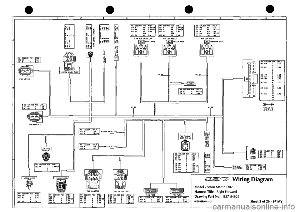
Wiring Diagram
Model
-
Aston Martin
DB7
Harness Title
-
Right Forward
Drawing Part No.
-
B37-84628
Revision
- 0
Sheet
3 of 26 - 97 MY
Page 152 of 421
fj
NO COLOUR 636 N 655
N
704
N
7r7 N
AREA e.M S.A6 9.DI 9.04
UPPER SOCKET LOWER SOCKET
BATTERY
STUDt
NO COLOUR 786
N
787
N
788
N
AREA I0.AZ-I5I
8.B6-75
IO.BI-90
BATTERY
STUDt
NO COLOUR
PIN
AREA
760
ON
U
9.C4-85
761 GW W I0.B?-9I
SPL 151
-
^w^
SPL 89 SPL 90
T^
SUNROOF/ACC
NO COLOUR PIN AREA 762 B I
e.B4-67
2 658
NP
3 8.A6 660 WG 4 8.A6
II
[D
fl]
(D
01 ^5 4
ABS LOOM
RED
764
BY
726 RB 645 WR 765 0
AREA
A4/5
ABS
LOOM
BROWN
NO COLOUR
PIN
AREA 656
NG
I 8.A6
766 NO
2
II.A3 3
REARWARD HARNESS NO COLOUR 767 KB
338 OY 769 KB 3
YS
340 OC
771
BR
772 OR 773 OU
PIN 1 2 3 4 5 e
7 8 9 10 II 12 13
AREA I0.B4-I04
I2.BI I2.AI 8.AI 12.81
10.82-96
I0.C2-I00 IO.C3-I02
SHEET
14
AREA
B/CI
-4
«
NO COLOUR
PIN
AREA
774 YW 775 B
776
B
199
K
779 NS
I0.B2-92 I0.B3-IIO II.C4-II9
II.CI I0.B3-ID9
NO COLOUR
344 RIN 822 0 781 8 316 B
346 UIN
348 YU
785
NS
PIN
? 3 4 5 6 7 8 9 10 II 12 13 14 15 16
AREA
I2.A3 I0.D5 I0.B4-II0 I2.A3
I2.A3
I2.A3
10.84-109
'YD 0 0
D D
0
D
a
do DD pan Dap'
SPL 105 SPL 106 SPL 107
16/0 D
0
D
0 0
D
0\'
e/flDDODaODDo\'
SHEET
II
AREA
81
-SPL 97
-SPL 98
-
SPL 99
-
SPL 100
-
SPL 101
-
SPL 102
NO /89 790 791 792 793 794 795 796 797 643 641 798 799 800
COLOUf BW B B YG B BR BW B S
wu
p RK BR B
Pll 1 2 1 4 b 6
/
8 9 10 II 12 13 14
AREA
8.B4-66
8.B3-64
8.B2-63
IOCS I0.C5 I0.C5 I2.C3-14I I2.C2-I37 10.05 8.A4 8.A4 I0.B2-93 I0.C5 I0.C5
ILOGIC
EARTH
'
NO COLOUR AREA
1004 BK I0.B5-I0! 1005 BK I0.B2-95
(f
D
D
•
a
D
•
DOZL
D
D
0
D
0
D
•
D
D
D
DCT D
D
D
a
0
0 13 24
AREA
C/OI
REARWARD HARNESS NO COLOUF 803 SLG 804 PC 805 PW 667 G 1 LC 335 OR 807 GB 808 K 809 YN 621 RU 810 BW 811 GW 336 0 813 LGO 814 OW 815 GP 816 OG 294
R
652
WU
330 LCO 797
S
304
YB
337
RN
PIN 1 ? 3 4 5 6 7 8 9 10 II 12 13 14 15 16 17 18 19 20 21 22 23 24
AREA 11.03
e.B2-6l
8.83-65
8.A6 8.BI I2.AI I0.C2-I0I I2.A5 I2.A5 8.C4 10.62-94 I0.B2-9I
12.
Al
10.82-97 I0.B2-99 II.C2-II5 10,82-98 I2.AI 8.A4 I2.AI I0.B4
12.
Al
I2.AI
c
Q
D
n
n
D
CZ
u
u
D
D
D
0
SC:
D
D
D
D
n
n
3
CZ
u
u
D
D
REARWARD HARNESS NO COLOUf 799
BR
794
BR
724
LGK
736 RIN 327 RIN
823
GR
792 YG 824 SR 800 8 793 8 737 UIN 326 UIN 826
SW
827
R
828
BG
829
RN
374 0 723 LGS 822 0 177 YW
PIN 1 2 3 4 4 5 6 7 8 9 10 II 12 12 13 14 15 16 17 IB 19 20 21 22 23
AREA I0.B4 I0.B4 I2.CI 9.B4 I2.AI
9.C2-79
I0.B4 11.03 I0.B4 I0.D4 9.B4 I2.A1 11.03
9.C4-84
I0.B5-I06
9.C3-80
I0.B5-III I1.B3-I16 I0.A6 10.82-92
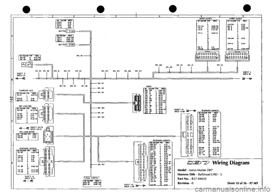
Wiring
Diagram
Model
- Aston Martin DB7
Harness
Title - Bulkhead LHD - 3
Part
No. - B37-84635
Revision
- 0
Sheet
10 of 26-97 MY
Page 154 of 421
NO COLOUF 890 N 891
NK
892 N 893 P 894 N 895 NW 896 N 131
NS
897 N 898 P 88SN 899 NP 900 W 339 WR 901
W
902
0
903 WK 904 OW 905
W
188
G
906 N 907 PN
PIN 1 ? 3 4 S 6 7 8 9 10 II 1? 13 14 15 16 17 18 19 ?0 21 22
AREA II.A5-I24 I2.C6 II.A5-I25 IZ.C2-I39 II.A5-126 I2.C3 11.45-125 I2.A4 II.A5-I26
e.B5-7l
II.A6 I2.D2 I2.CI~I29 12.81 I2.CH29 II.B4-I2I II.B5-I28 12.06 I2.CI-I29 II.BI II.A5-I24 1I.B2-II3
25JL25n 27n 29n 3in 33n 35n 37n 39n ''ia,''3rL
24V26V28V3oV,2*34V3sV38V4oV42V44V
NO COLOUF 908 N 909 NG 910
KB
193
KB
911
W
834 G 912
WK 770 10
913
WK
820
0?
914
W
865 LGS 915
N
870 RW 916
KB
297 NS 917
N
918
P
919
N
185
NR
888 N 766 NO
PIN ?3 ?4 25 ?6 27 28 29 30 31 3? 33 34 35 36 37 38 39 40 41 4? 43 44
AREA II.A5-I26 I2.C6 I2.C2-I32 II.CI I2.CI-I29 II.B3 II.B5-I28 II.CI II.B5-I28 11.01 12.01-129 II.B3~II8 II.B4-I23 II.C6 I2.C2-I3; I2.A1 II.A5-I24 II.B4-I22 II.B4-I23 11.81 II.Ae lO.CI
SPL
124 SPL 125 SPL 126
SHEET 10 AREA B6 iF^^i
-«-
SHEET
t
AREA
Bl
GEARBOX
RED
NO COLOUF 182
S
184
0
185
NR
186
BY
187
BU
188
G
189
SP
190
RK
191
GB
192
WS
193
KB
194
YG
195
GP
196
KU
197
BK
198
UN
199
K
PIN
1 2 3
4 5 6 / 8 9 10 II 1? 13 14 15 16 17
18 19 20
AREA 9.D2
I0.B3-III II.A3 12.A3 I2.A3 II.AI I2.A3 10.B2-93 9.A6 9.B4 II.A3 I2.A3 1I.C2-II5 9.A4 10,85-105 I2.A3 I0.A3
AIR CON UNIT
NO COLOUR
PIN
768
B
?70
LG
163
GN
780
W
782
PN
783 RW 784 R
1 2 3 4 5 6
7 8 9 10 II 12
AREA 12.03-143 II.A3 I2.A4 12.01-129 II.B2-II3 II.B2-II4 I0.B4-84
NO COLOUF 817
YO
818
RG
819
OR
379
RU
380
GU
820
GP
821
RW
121
Y
825
BP
731
U
2200
LGY
332
B
PIN 1 2 3 4 5 6 7 8 9 10
II 12 13 14 15 16
AREA 11.03 12.02-134 12.06 I0.B4-I0a 8.DI II.A3 II.B2-II4 8.AI
9.B3-8I
9.B3-83
9.B3-82
12.03-143
<^
• SHEET 13 •AREA B6
NO COLOUR
PIN
AREA 876
RU U
IO.B4-10S 877
RG
W -
I2.BI-I30 SPL
123
-
SPL
122
-
SPL 121
-
SPL
117
SPL
118
c
AUTO
G/BOX HARNESS
SHEET
7 v^ r-
AREA
CI -** »"
cx
NO OOLOUF 830 BG 803 SLG 123
GP
831
GP
832
GB
833 PH 834
0
713
YN
714
YB
835
B
836 BG 52
GP 49 GP
PIN 1 2 3 4 5 6 7 8 9 10 11 12 13
AREA lO.BS-IOt 10.04 S.BI ILC2-II5 I0.C2-I0I 11.02-113 II.A3 9.03 9.03 I2.C2-I30 I2.AI
8.AI 8.AI
CO]
01
EXHAUST
TEMP/
SPEED WARNING
NO COLOUR 837
B
729
PS
838 PS 839
WP
840 WY 841
W
PIN 1 2 3 4 5 6
AREA 12.02-131 9.A4 12.A5 I2.A5
9.B5-87
I2.BI-129 PASSENGER AIRBAG
BINNACLE
I
(=3;
era
ra
i(=r
NO OOLOUF 842
KB
843 BK 600 PR 844 U 620
Y
845 RK 47
RO
646 PN e47LG 824 SR 848 BU 649 RW 850
B
826 SW 851
BY
852 NY 853 RN 854
WB
617
R
855
U
856 BP 857
LGY
817
YO
PIN 1 ? 3 4 5 6 / 8 9 10 11 12 13 14 15 16 17 18 19 20 21 22 23 24
AREA I2.A1
I0.B5-I0!
8.A3
9.05-86
8.04 I0.B2-93 8.BI II.B2-II3
e.B5-69
10.05 II.B4-I27 II.B2-I14 12.02-131 10.05 12.02 12.03-144
I0.B5-10;
I2.A5 8.03
9.B3-83
9.B3-8I
9.B3-82
11.01
SPL
127 SPL 128
c
IcX
|[=r
NO COLOUR
PIN
AREA 858
RP I
11.04-120 2 859 KP
3 11.06
I BATTERY
~| STUD
NO COLOUI 881
N
882 N 883 N 884
N
885
N
886 N 667
N
886 N
AREA II.A5-I24 II.A5-I26 II.A6 I2.CI ILAI I1.A5-I25 II.B4-I23 I1.B3
CB CD NO COLOUR PIN 883 N I 869 N 2
AREA II.A6 I2.D3
WIPER LOGIC NO COLOUF 874
B
875 0 683 LGG 681 LGW 680 LGN 285
BLG
287
WLG
286
BR
145 LGB
678 LGP 879 LC 676 LGR 880 BS
PIN 1 2 i 4 b 6 7 8 9 10 II 12 13 14 15 16
MODULE AREA I2.C4 II.B4-I2I 9.AI 9.AI 9.AI 12.B3 12.B3 12.B3 12.A4
9.AI IO.Bl-89 9.AI 1I.B2-II6
AIRBAG DIAGNOSTIC MONITOR GREY NO COLOUR 865 LGS 866 ON 867 B 868 YW 869 B 367 YU 870
RW
871 RN 672
RG
873
KU
368 KG
PIN 1 2 3 4 5 6 7 8 9 10 II 12
AREA 11.03-118 12.A6 11.04-119 10.82-92 11.04-119 8.CI II.A3
12.85 12.85
12.
A6 8.CI
AIRBAG DIAGNOSTIC MONITOR BLACK NO COLOUR
860 RP 859 KP 697 KN
861
RP
862
YG
863 OP 369 OW
864
YP
PIN
2 3 4 5 S 7 8 9 10 11 12
AREA
I1.C4-120 II.D4 9.B2 ILC4-I20 12.B5
I2.B6
e.oi
I2.B5
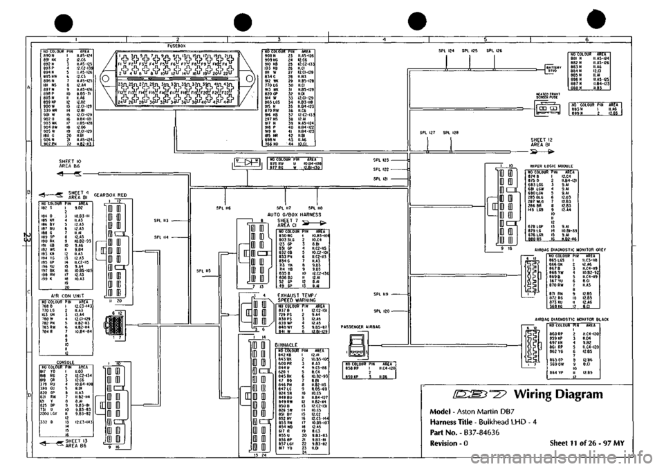
""^^ Wiring Diagram
Model - Aston Martin DB7
Harness Title - Bulkhead LHD - 4
Part No. - B37-84636
Revision - 0 Sheet 11 of 26-97 MY
Page 187 of 421
^=2?
Electrics
Airbag System
Eye Protection
Chemical protective goggles are recommended
where there is a possibility of eye contact with the
propellant. Safety glasses with side shields are
recommended for all other operations.
Protective Clothing
Approved protective gloves, overalls and shoes/
boots should be worn.
Handling and Storage Precautions
Do not store airbag modules near live electrical
equipment or circuitry. Store in a dry environment
at ambient temperatures.
Good housekeeping and engineering practices
should be employed to prevent the generation and
accumulation of
dusts.
Store in compliance with all
local state and federal regulations.
Driver and Passenger Airbag Modules
Assembly/Removal/Service Instructions
WARNING: In the event of a vehicle impact where the
airbags and the seatbeltpretensioner (if fitted) are
deployed, the following actions MUST be
performed:
Check the condition of the seatbelts, steering
wheel,
steering column, all connections to airbags,
and the column switchgear connectors for integrity
and damage. If in any
doubt,
replace suspected
parts for new parts.
Replace both crash
sensors,
the
safing sensor
and
the seatbelt pretensioner module (if fitted).
On completion of all repair procedures, switch on
the ignition and check that the
Airbag/SRS
warning
light comes on when the ignition is switched on
and extinguishes after approximately six seconds
indicating satisfactory completion of the airbag
and pretensioner
system
self
tests.
WARNING: Before starting
work,
ensure
that the ignition
switch is in position 'O' and the ignition key is
removed.
Disconnect the battery negative lead
within 12 seconds of switching off the ignition to
prevent the alarm system triggering.
As the airbag control module is equipped with a
back-up power source and due to the risk of the
airbag being inadvertently deployed, wait one
minute or longer after disconnecting the battery
before starting work on the airbag module.
• Disconnectingthe battery negative cable cancels
the memory for the 'one-touch' window down
system and stops the vehicle clock. Reset the
window memory and the clock when work is
completed.
• Never use airbags from other vehicles, always
use new parts.
• After work is completed, reconnect the battery
and perform the airbag warning light check
• Never use electrical probes to check voltage or
electrical resistance of the airbag modules.
• Disconnect the airbag before carrying out any
work on, or in the vicinity of the module, or
when using electric welding equipment.
• Always ensure that the battery negative lead has
been disconnected for at least one minute before
commencing any removal procedure.
September 1996 6-71
Page 188 of 421
Electrics
Airbag System =7?
Spillage and Leakage
If material is spilled or released, contact Aston
Martin Technical Support for advice on clean-up
procedures. All personnel must be kept away from
the contaminated area.
Do not dispose of contaminated propellant or
water into storm or sanitary sewers, ground water
or
soil.
Spills may be reportable to state and/or federal
authorities.
Materials must be disposed of by incineration or
chemical oxidation under carefully controlled
conditions by specially trained individuals and in
accordancewith local stateandfederal regulations.
Scrapping Vehicles with Live Airbags
when scrapping a vehicle with live airbags, first
deploy the airbags in accordance with the following
procedure. This procedure assumes that the airbag
wiring is undamaged
See Handling/Safety Information.
If the airbags are to be removed, see the airbag
module assembly/removal/servicing instructions.
Equipment required:
Four insulation displacement connectors
(scotch locks).
Charged 'slave' battery.
Two 10 metre lengths of
1
mm^ wire fitted with
crocodile clips on one end.
Procedure
WARNING: The deployment procedure must be
carried out outdoors away from other personnel.
1.
Remove any loose debris from around the airbag
modules and ensure that no flammable liquids are
present.
2.
Disconnect the vehicle battery.
WARNING: Always connect to the airbag
first,
as
the bag will deploy immediately on connection to
the battery.
3. Remove the passenger side airbag deployment
door and underscuttle panel.
4.
Remove the drivers side underscuttle panel.
5. Disconnect the airbag connector for the spiral
cassette under the fascia and at the wire (drivers
side).
6. Locate the harness connectors and cut the wires
leading from the airbag just above the mating plug
(passengers side).
Note: The harness connected between the driver's
airbag
and the connector
has
one red
feed
wire and
one
grey/orange return
wire.
The
harness
connected between
the
passenger's
airbag and the connector
has
one blue/
orange
feed wire and one
pinl
return wire.
6-72 September1996
Page 189 of 421
^^
Electrics
Airbag System
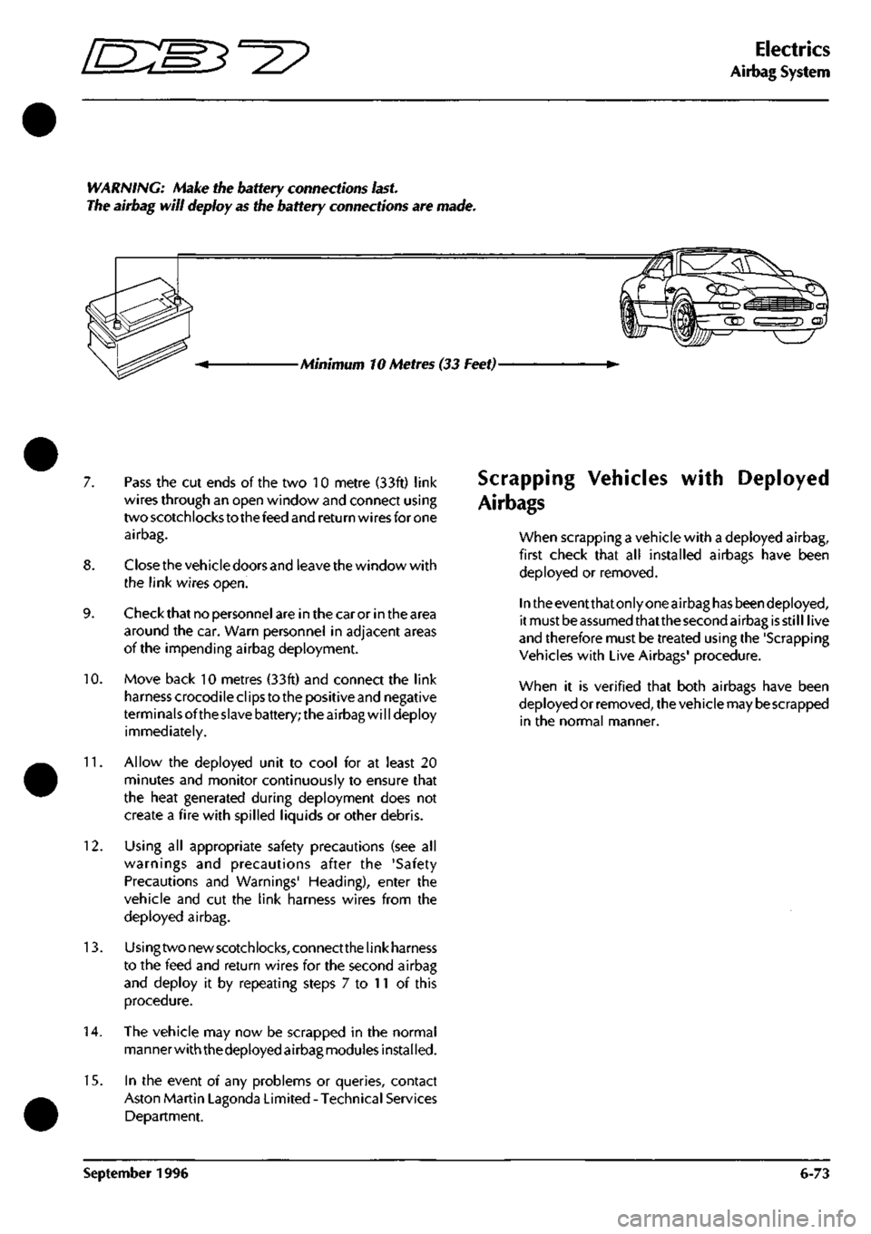
WARNING: Make the battery connections
last.
The airbag will deploy as the battery connections are made.
Minimum 10 Metres (33 Feet)-
7. Pass the cut ends of the two 10 metre (33ft) link
wires through an open window and connect using
two scotchlocks to the feed and return wires for one
airbag.
8. Closethe vehicle doors and leave the window with
the link wires open.
9. Check that no personnel are in the car or in the area
around the car. Warn personnel in adjacent areas
of the impending airbag deployment.
10.
Move back 10 metres (33ft) and connect the link
harness crocodile clips to the positive and negative
terminals ofthe slave battery; the airbag will deploy
immediately.
11.
Allow the deployed unit to cool for at least 20
minutes and monitor continuously to ensure that
the heat generated during deployment does not
create a fire with spilled liquids or other debris.
12.
Using all appropriate safety precautions (see all
warnings and precautions after the 'Safety
Precautions and Warnings' Heading), enter the
vehicle and cut the link harness wires from the
deployed airbag.
13.
Usingtwonewscotchlocks,connectthelinkharness
to the feed and return wires for the second airbag
and deploy it by repeating steps 7 to 11 of this
procedure.
14.
The vehicle may now be scrapped in the normal
manner with thedeployed airbag modules installed.
15.
In the event of any problems or queries, contact
Aston Martin Lagonda Limited - Technical Services
Department.
Scrapping Vehicles
Air bags
with Deployed
when scrapping a vehicle with a deployed airbag,
first check that all installed airbags have been
deployed or removed.
In the eventthatonly one airbag has beendeployed,
it must be assumed thatthe second airbag is still live
and therefore must be treated using the 'Scrapping
Vehicles with Live Airbags' procedure.
when it is verified that both airbags have been
deployed or removed, the vehicle may
be
scrapped
in the normal manner.
September 1996 6-73
Page 190 of 421
Electrics
Airbag System E:m3^2?
Disposal of Live Airbags
Modu
les
removed/renewed by Aston Martin dealers
are to be deployed using the following procedure.
WARNING: Never use a customer's vehicle to
deploy airbags.
Equipment Required:
Link harness
'Slave'
battery
Safety goggles to BS 2092 grade 2 or equivalent
Rubber gloves to PrEN 374 class 2 or equivalent
Ear protectors
Particulate respirator to EN 149 grade FFP 25
Deployment cage
Note: If you do not
have access
to a deployment
cage,
please
contact Aston Martin
Lagonda
Limited
Technical
Support Department for advice.
Procedure
This procedure must be performed outdoors, away
from other personnel.
Remove any loose debris from around the airbag
and ensure that no flammable liquids are present.
Assemble the disposal cabinet and fit the airbag as
shown in figure 1 in line with the following
procedures:
a) Remove the mesh guard from the rig frame.
b) Attach the guard to the frame by bolting the
hinges to the frame.
c) Ensure the relevant plate is fitted and rotate into
position.
d) Fit and secure the airbag module onto the plate.
e) Clamp the plate down using the two toggle
clamps.
f) Close the mesh guard.
Note: The harness connected between the driver's
airbag and
the
connector
has
one red
feed
wire and one
grey/orange return wire. The harness connected between
the
passenger's
airbag and the connector
has
one blue/
orange feed wire and one pink/black return wire.
Connect the 10 metre {33ft) link harness to the
airbag.
Ensure that no personnel are in the vicinity of the
cabinet.
5. Move 10 metres (33ft) and connect the link harness
crocodile clips to the 'slave' battery; the airbag will
deploy immediately.
6. Allow the unit to cool for at least 20 minutes.
7. Open the mesh guard and remove the deployed
airbag module.
Note: Should the
design
of your deployment
cage
differ
from that described above, please contact the cage
manufacturer for advice on mounting the airbag.
8. Seal the deployed module into a plastic bag ready
for disposal.
9. In the event of any problems or queries, contact
Aston Martin Lagonda Limited -Technical Services
Department.
Disposal of Deployed Airbags
Deployed airbags are to be disposed of as special
waste and disposal must comply with local
environmental requirements. If
in
any doubt, contact
the local authority for disposal instructions.
Note; The storage, transportation, disposal and/or
recycling of airbag module components must be
performed in accordance with all applicable federal,
state
and local regulations including, but not limited to,
those
governing building and fire
codes,
environmental
protection, occupational health and safety and
transportation.
Modules removed and deployed by Aston Martin
Dealers are to be returned to Aston Martin Lagonda
Limited for disposal following prior consultation.
6-74 September 1996
Page 191 of 421
'=2?
Electrics
Airbag System
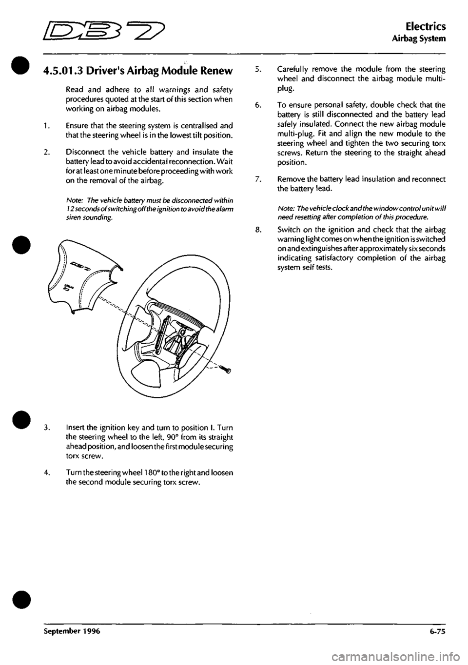
4.5.01.3 Driver's Airbag Module Renew
Read and adhere to all warnings and safety
procedures quoted at the start of this section when
working on airbag modules.
1.
Ensure that the steering system is centralised and
that the steering wheel is in the lowest tilt position.
2.
Disconnect the vehicle battery and insulate the
battery lead to avoid accidental reconnection. Wait
for at least one minute before proceeding with work
on the removal of the airbag.
Hote: The vehicle battery
must be
disconnected within
12 seconds of switching off
the
ignition to avoid the alarm
siren sounding.
5. Carefully remove the module from the steering
wheel and disconnect the airbag module multi-
plug.
6. To ensure personal safety, double check that the
battery is still disconnected and the battery lead
safely insulated. Connect the new airbag module
multi-plug.
Fit and align the new module to the
steering wheel and tighten the two securing torx
screws. Return the steering to the straight ahead
position.
7. Remove the battery lead insulation and reconnect
the battery
lead.
Note:
The vehicle
clockandthe window control unitwill
need
resetting
after completion of
this
procedure.
8. Switch on the ignition and check that the airbag
warni ng
I
ight comes on when the ignition is switched
on and extinguishes after approximately sixseconds
indicating satisfactory completion of the airbag
system self tests.
Insert the ignition key and turn to position I. Turn
the steering wheel to the left, 90° from its straight
ahead position, and loosen thefirstmoduiesecuring
torx screw.
Turn the steering wheehSO" to the rightand loosen
the second module securing torx screw.
September 1996 6-75
Page 192 of 421
Electrics
Airbag System ^^?
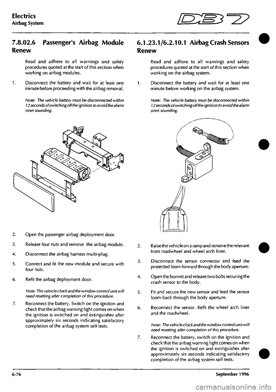
7.8.02.6
Renew
Passenger's Airbag Module
Read and adhere to all warnings and safety
procedures quoted at the start of this section when
working on airbag modules.
Disconnect the battery and wait for at least one
minute before proceeding with the airbag removal.
Note:
The
vehicle battery
must
be disconnected within
12
seconds
of switchingoff
the
ignition
to
avoid the alarm
siren sounding.
2. Open the passenger airbag deployment door.
3. Release four nuts and remove the airbag module.
4.
Disconnect the airbag harness multi-plug.
5. Connect and fit the new module and secure with
four nuts.
6. Refit the airbag deployment door.
Note:
The vehicle
clock and
the
window control unit will
need
resetting
after completion of
this
procedure.
7. Reconnect the battery. Switch on the ignition and
check that the airbag warning
I
ight comes on when
the ignition is switched on and extinguishes after
approximately six seconds indicating satisfactory
completion of the airbag system self tests.
6.1.23.1/6.2.10.1 Airbag
Crash
Sensors
Renew
Read and adhere to all warnings and safety
procedures quoted at the start of this section when
working on the airbag system.
1.
Disconnect the battery and wait for at least one
minute before working on the airbag system.
Note: The vehicle
battery
must be disconnected within
12
seconds
of switchingoff
the
ignition
to
avoid thealarm
siren sounding.
4.
5.
Raisethevehicleon a rampand remove the relevant
front roadwheel and wheel arch liner.
Disconnect the sensor connector and feed the
protected loom forward through the body aperture.
Open the bonnet and release two bolts securing the
crash sensor to the body.
Fit and secure the new sensor and feed the sensor
loom back through the body aperture.
Reconnect the sensor. Refit the wheel arch liner
and the roadwheel.
Note:
The vehicle
clock and
the
window control unit will
need
resetting
after completion of
this
procedure.
Reconnect the battery, switch on the ignition and
check that the airbag warning
I
ight comes on when
the ignition is switched on and extinguishes after
approximately six seconds indicating satisfactory
completion of the airbag system self tests.
6-76 September 1996