sensor ASTON MARTIN DB7 1997 Repair Manual
[x] Cancel search | Manufacturer: ASTON MARTIN, Model Year: 1997, Model line: DB7, Model: ASTON MARTIN DB7 1997Pages: 421, PDF Size: 9.31 MB
Page 296 of 421
^2?
Air Conditioning
Electronic Control Module
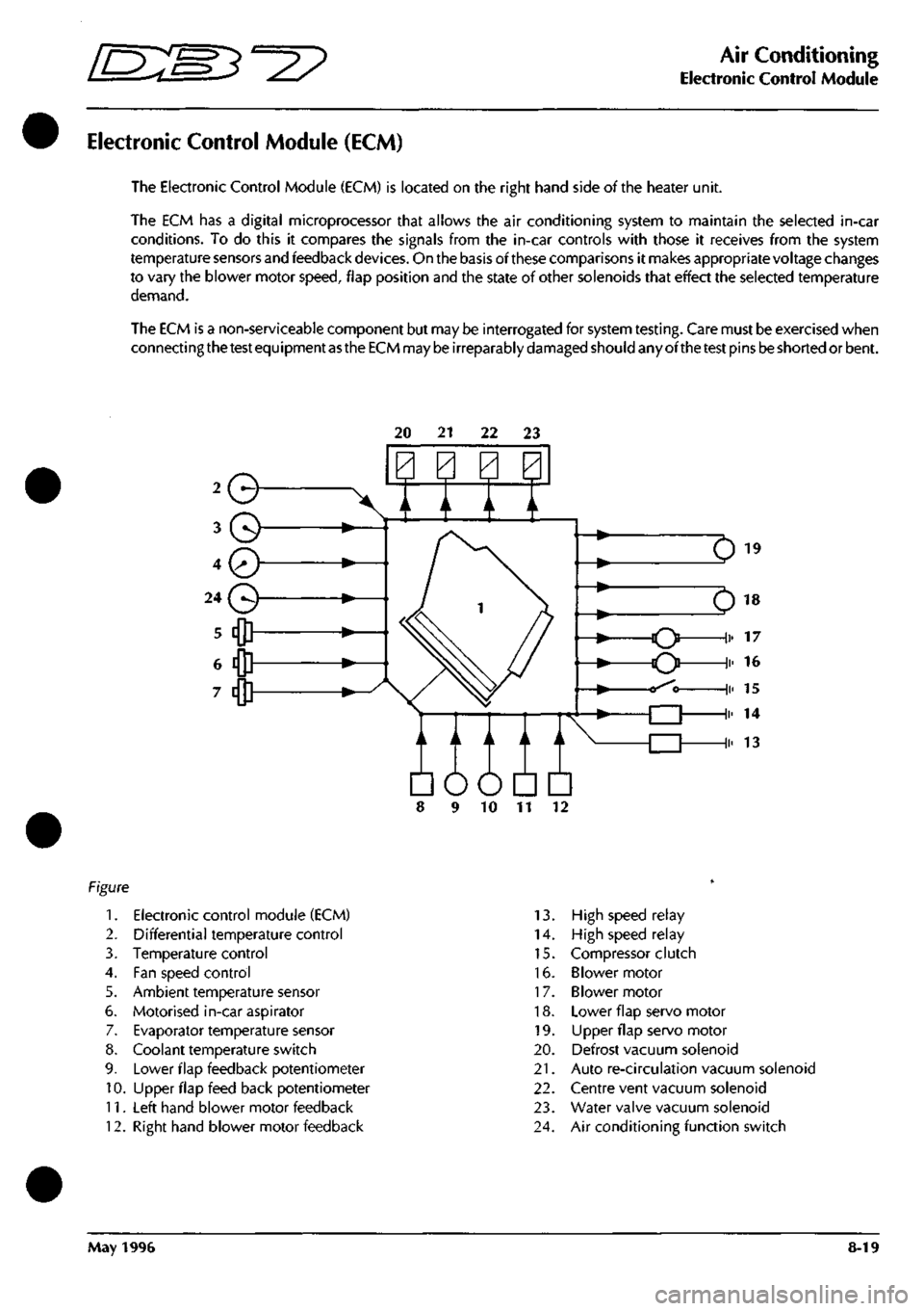
Electronic Control Module (ECM)
The Electronic Control Module (ECM) is located on the right hand side of the heater unit.
The ECM has a digital microprocessor that allows the air conditioning system to maintain the selected in-car
conditions. To do this it compares the signals from the in-car controls with those it receives from the system
temperature sensors and feedback
devices.
On the basis of these comparisons it makes appropriate voltage changes
to vary the blower motor
speed,
flap position and the state of other solenoids that effect the selected temperature
demand.
The ECM is a non-serviceable component but may be interrogated for system
testing.
Care must be exercised when
connecting
the test
equipment
as the ECM
may
be
irreparably
damaged
should any ofthe
test
pins
be
shorted or bent.
20 21 22 23
Q
A / A \/
Em
10 11
1.
Electronic control module (ECM)
2.
Differential temperature control
3. Temperature control
4.
Fan speed control
5. Ambient temperature sensor
6. Motorised in-car aspirator
7. Evaporator temperature sensor
8. Coolant temperature switch
9. Lower flap feedback potentiometer
10.
Upper flap feed back potentiometer
11.
Left hand blower motor feedback
12.
Right hand blower motor feedback
13.
High speed relay
14.
High speed relay
15.
Compressor clutch
16.
Blower motor
17.
Blower motor
18.
Lower flap servo motor
19.
LIpper flap servo motor
20.
Defrost vacuum solenoid
21.
Auto re-circulation vacuum solenoid
22.
Centre vent vacuum solenoid
23.
Water valve vacuum solenoid
24.
Air conditioning function switch
May 1996 8-19
Page 297 of 421
Air Conditioning
Electronic Control Module r^^?
Description
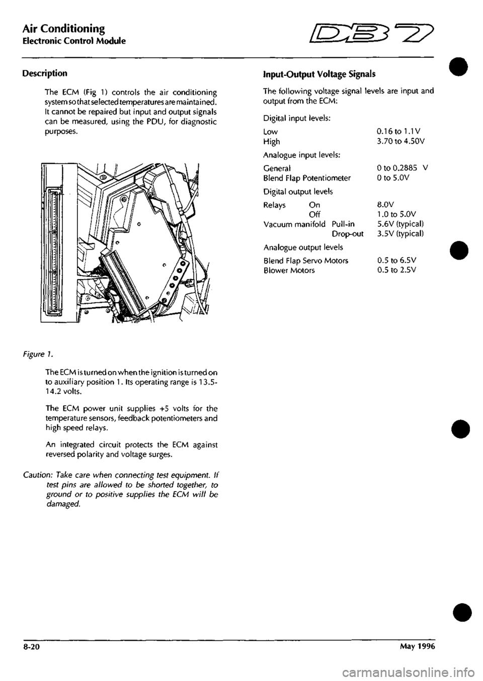
The ECM (Fig 1) controls the air conditioning
system so that selected temperaturesare maintained.
It cannot be repaired but input and output signals
can be measured, using the PDU, for diagnostic
purposes.
Input-Output Voltage Signals
The following voltage signal levels are input and
output from the ECM:
Digital input levels:
Low
High
Analogue input levels:
General
Blend Flap Potentiometer
Digital output levels
Relays On
Off
Vacuum manifold Pull-in
Drop-out
Analogue output levels
Blend Flap Servo Motors
Blower Motors
0.16 to 1.1V
3.70 to 4.50V
0 to 0.2885 V
0 to 5.0V
8.0V
1.0 to 5.0V
5.6V (typical)
3.5V (typical)
0.5 to 6.5V
0.5 to 2.5V
figure 1.
The ECM
is
turned on when the ignition
is
turned on
to auxiliary position 1. its operating range is 13.5-
14.2 volts.
The ECM power unit supplies +5 volts for the
temperature sensors, feedback potentiometers and
high speed relays.
An integrated circuit protects the ECM against
reversed polarity and voltage surges.
Caution: Take care when connecting test equipment. If
test pins are allowed to be shorted together, to
ground or to positive supplies the ECM will be
damaged.
8-20 May 1996
Page 300 of 421
'^^p
Air Conditioning
In Car Controls
Fan Speed Control Switch (Mode Switch)
SC On Mode
The system is not operational, a residual
signal to the ECM ensures that the blower
flaps are closed to prevent air entering the
system.
1.
Low Blower Mode
The fan speed is lowandtheairconditioning
function switch is fully operational. Pin 13
on the ECM is earthed through the switch
and a 12V signal is returned to Pin 44.
2.
Medium Blower Mode
The fan runs at medium speed and the
function switch is fully operational. Pin 14
of the ECM is earthed through the switch
and a 12V signal is returned to Pin 44.
3. High Blower Mode
The fan speed is high and the function
switch is fully operational. Pin 15 at the
ECM is earthed through the switch and a
12V signal is returned to Pin 44.
DEF Defrost Blower Mode
The fan speed is
high,
the function switch
and temperature switch are not operational,
front screen vents are fully open and lower
flaps are fully closed. Pin 27 at the ECM is
earthed through the switch and a 12V signal
is returned to Pin 44.
Temperature Sensors
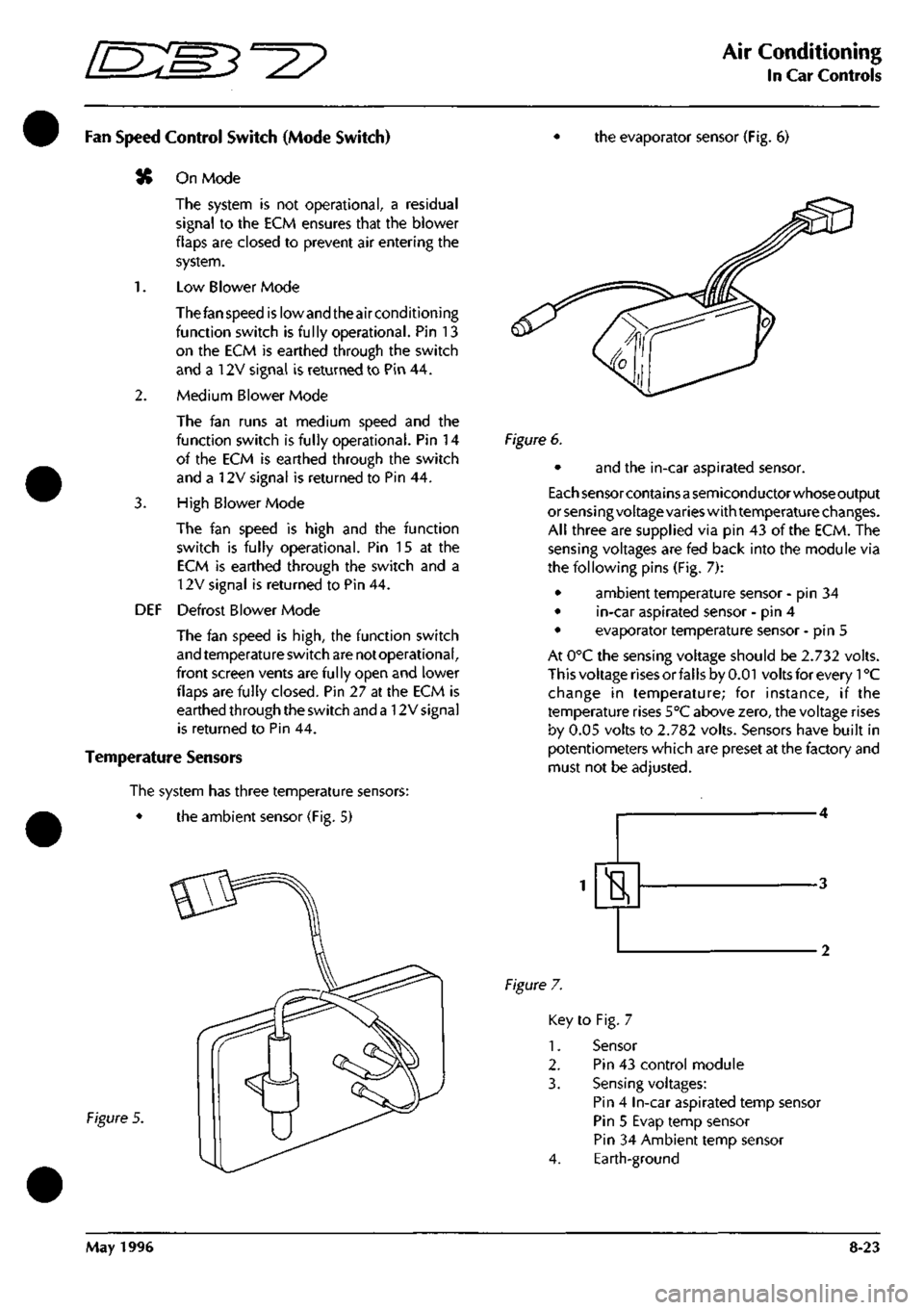
The system has three temperature sensors:
• the ambient sensor (Fig. 5)
the evaporator sensor (Fig. 6)
Figure 5.
Figure 6.
• and the in-car aspirated sensor.
Each sensor containsa semiconductor whose output
or sensing voltage varies with temperature changes.
All three are supplied via pin 43 of the ECM. The
sensing voltages are fed back into the module via
the following pins (Fig. 7):
• ambient temperature sensor - pin 34
• in-car aspirated sensor - pin 4
• evaporator temperature sensor - pin 5
At 0°C the sensing voltage should be 2.732 volts.
This voltage rises or falls by 0.01 volts for every 1°C
change in temperature; for instance, if the
temperature rises 5°C above zero, the voltage rises
by 0.05 volts to 2.782 volts. Sensors have built in
potentiometers which are preset at the factory and
must not be adjusted.
H
Figure 7.
Key to Fig. 7
1.
Sensor
2.
Pin 43 control module
3. Sensing voltages:
Pin 4 In-car aspirated temp sensor
Pin 5 Evap temp sensor
Pin 34 Ambient temp sensor
4.
Earth-ground
May 1996 8-23
Page 301 of 421

Air Conditioning
In Car Controls ^2?
Evaporator Sensor
The evaporator sensor allov^^s the ECM to monitor
the temperature ofthe refrigerant in the evaporator
core continuously. When the temperature falls
below 0°C the ECM de-energises the compressor's
electromagnetic clutch and prevents refrigerant
from flowing through the system. The clutch is re
engaged when the temperature rises.
Motorised In-Car Aspirated Sensor
The motorised aspirator (Fig. 8), which is fitted to
the passenger side facia underscuttle panel,
incorporates a motor driven fan (Fig. 8-1) that
draws air continuously over the in car temperature
sensor (Fig. 8-2).
Figure 8.
Key
1.
2.
3.
4.
5.
to Fig. 8
Motor
Sensor
Fan
Connector SCAO07
Connector SAC030
The motor (Fig. 8-1) is supplied, independently of
the air conditioning
system,
from the ign ition switch
(position 2). Its operating voltage range is 13.5 to
14.2 volts. Maximum current is 120 mA. The sensor
(Fig.
8-2) has a temperature operating range of -
30°C to +85°C. It is fed with 5 volts from the ECM
(pin 43), while the sensing voltage
is
supplied to pin
4 ofthe ECM. At 0°C the sensing voltage is 2.732V
± 0.002V. The rate of change of sensing voltage is
0.01 V± 0.002V per 1°C.
LC/0
0^5
U
Figure 9.
Key to Fig. 9
1.
Ignition switched supply to motor
2.
+5V supply to sensor from pin 43 of ECM
3. Sensor voltage output to pin 10 of ECM
4.
Sensor earth-ground to pin 4 of ECM
5. Motor earth-ground
A. Motor
B. Sensor
Ambient Temperature Sensor
An ambient temperature sensor (Fig. 10-1) is fitted
in the plenum air intake to provide the ECM with
information on the temperature ofthe air entering
the air conditioning unit and so offset the in-car
temperature at extremes of ambient. The voltage
signal output from the sensor is proportional to the
temperature of the surrounding air. The sensor
temperature range is -30°C to 85°C. At 0°C the
output ofthe sensor is 2.732V ± 0.005V. The rate
of change is + 0.01 V ± 0.002V per
1
°C.
Figure 10.
Key to Fig. 10
1.
Ambient temperature sensor
2.
+5 volts from ECM Pin 43
3. Sensing signal to ECM Pin 34
4.
Earth-ground
8-24 May 1996
Page 307 of 421
Air Conditioning
System Fault Diagnosis ^=2?
System Fault Diagnosis
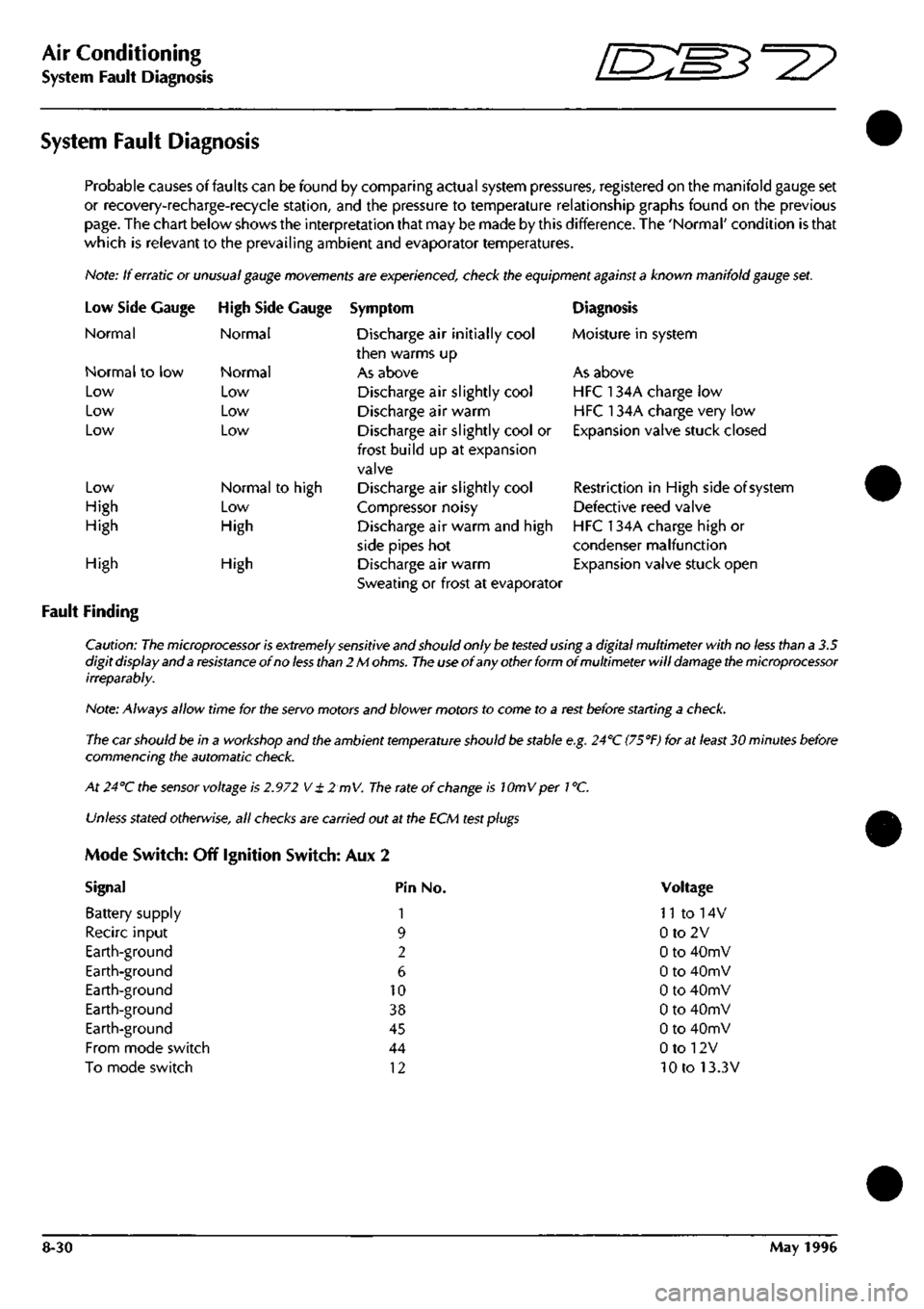
Probable causes of faults can be found by comparing actual system pressures, registered on the manifold gauge set
or recovery-recharge-recycie station, and the pressure to temperature relationship graphs found on the previous
page.
The chart below shows the interpretation that may be made by this difference. The 'Normal' condition is that
which is relevant to the prevailing ambient and evaporator temperatures.
Note: If erratic or
unusual gauge movements
are experienced, check the equipment
against a
known manifold
gauge
set.
Low Side
Normal
Gauge
Normal to low
Low
Low
Low
Low
High
High
High Side Gauge
Normal
Normal
Low
Low
Low
Normal to high
Low
High
High
Fault Finding
High
Symptom
Discharge air initially cool
then warms up
As above
Discharge air slightly cool
Discharge air warm
Discharge air slightly cool or
frost build up at expansion
valve
Discharge air slightly cool
Compressor noisy
Discharge air warm and high
side pipes hot
Discharge air warm
Sweating or frost at evaporator
Diagnosis
Moisture in system
As above
HFC 134A charge low
HFC 134A charge very low
Expansion valve stuck closed
Restriction in High side of system
Defective reed valve
HFC 134A charge high or
condenser malfunction
Expansion valve stuck open
Caution:
The microprocessor is extremely sensitive
and should only
be tested
using
a
digital multimeter with no
less
than a 3.5
digit display and a
resistance
of no
less than
2 M
ohms.
The use
of any other form of multimeter will
damage the microprocessor
irreparably.
Note: Always allow time for the
servo
motors and blower motors to come to a
rest
before starting a
check.
The car should be in a workshop and the ambient
temperature
should
be
stable
e.g.
24''C
(75°F)
for at
least
30 minutes before
commencing the automatic
check.
At 24°C the
sensor
voltage is
2.972
V
± 2 mV.
The
rate of
change
is lOmVper
1
°C.
Unless
stated
otherwise,
all
checks
are carried out at the ECM
test plugs
Mode Switch: Off Ignition Switch: Aux 2
Signal Pin No.
Battery supply 1
Recirc input 9
Earth-ground 2
Earth-ground 6
Earth-ground 10
Earth-ground 38
Earth-ground 45
From mode switch 44
To mode switch 12
Voltage
n to 14v
0to2V
0 to 40mV
0 to 40mV
0 to 40mV
0 to 40mV
0 to 40mV
0 to 12V
10 to 13.3V
8-30 May 1996
Page 308 of 421
"3^2?
Air Conditioning
System Fault Diagnosis
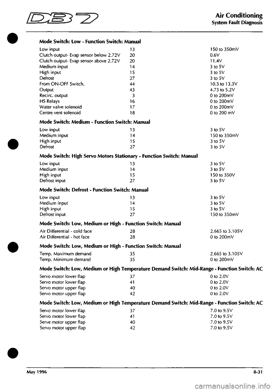
Mode Switch: Low - Function Switch: Manual
Low input 13
Clutch output- Evap sensor below 2.72V 20
Clutch output- Evap sensor above 2.72V 20
Medium input 14
High input 15
Defrost 27
From ON-OFF Switch. 44
Output 43
Recirc. output 3
HS Relays 16
Water valve solenoid 17
Centre vent solenoid 18
Mode Switch: Medium - Function Switch: Manual
Low input
Medium input
High input
Defrost
13
14
15
27
Mode Switch: High Servo Motors Stationary - Function Switch: Manual
Low input 13
Medium input 14
High input 15
Defrost input 27
Mode Switch: Defrost - Function Switch: Manual
Low input
Medium input
High input
Defrost input
13
14
15
27
Mode Switch: Low, Medium or High - Function Switch: Manual
Air Differential - cold face 28
Air Differential - hot face 28
Mode Switch: Low, Medium or High - Function Switch: Manual
Temp.
Maximum demand 35
Temp.
Minimum demand 35
150 to 350mV
0.6V
11.4V
3to5V
3to5V
3to5V
10.3 to 13.3V
4.73 to 5.2V
0 to 200mV
0 to 200mV
0 to 200mV
0 to 200 mV
3to5V
150 to 350mV
3to5V
3to5V
3to5V
3to5V
150 to 350V
3to5V
3to5V
3to5V
3to5V
150 to 350mV
2.665 to 3.105V
0 to 200mV
2.665 to 3.105V
0 to 200mV
Mode Switch: Low, Medium or High Temperature Demand Switch: Mid-Range - Function Switch: AC
Servo motor lower flap 37 0 to 2.0V
Servo motor lower flap 41 0 to 2.0V
Servo motor upper flap 40 0 to 2.0V
Servo motor upper flap 42 0 to 2.0V
Mode Switch: Low, Medium or High Temperature Demand Switch: Mid-Range - Function Switch: AC
Servo motor lower flap 37 7.0 to 9.5V
Servo motor lower flap 41 7.0 to 9.5V
Serve motor upper flap 40 7.0 to 9.5V
Servo motor upper flap 42 7.0 to 9.5V
May 1996 8-31
Page 333 of 421
Air Conditioning Repair Procedures
Air-Conditioning Unit Renew ^^?
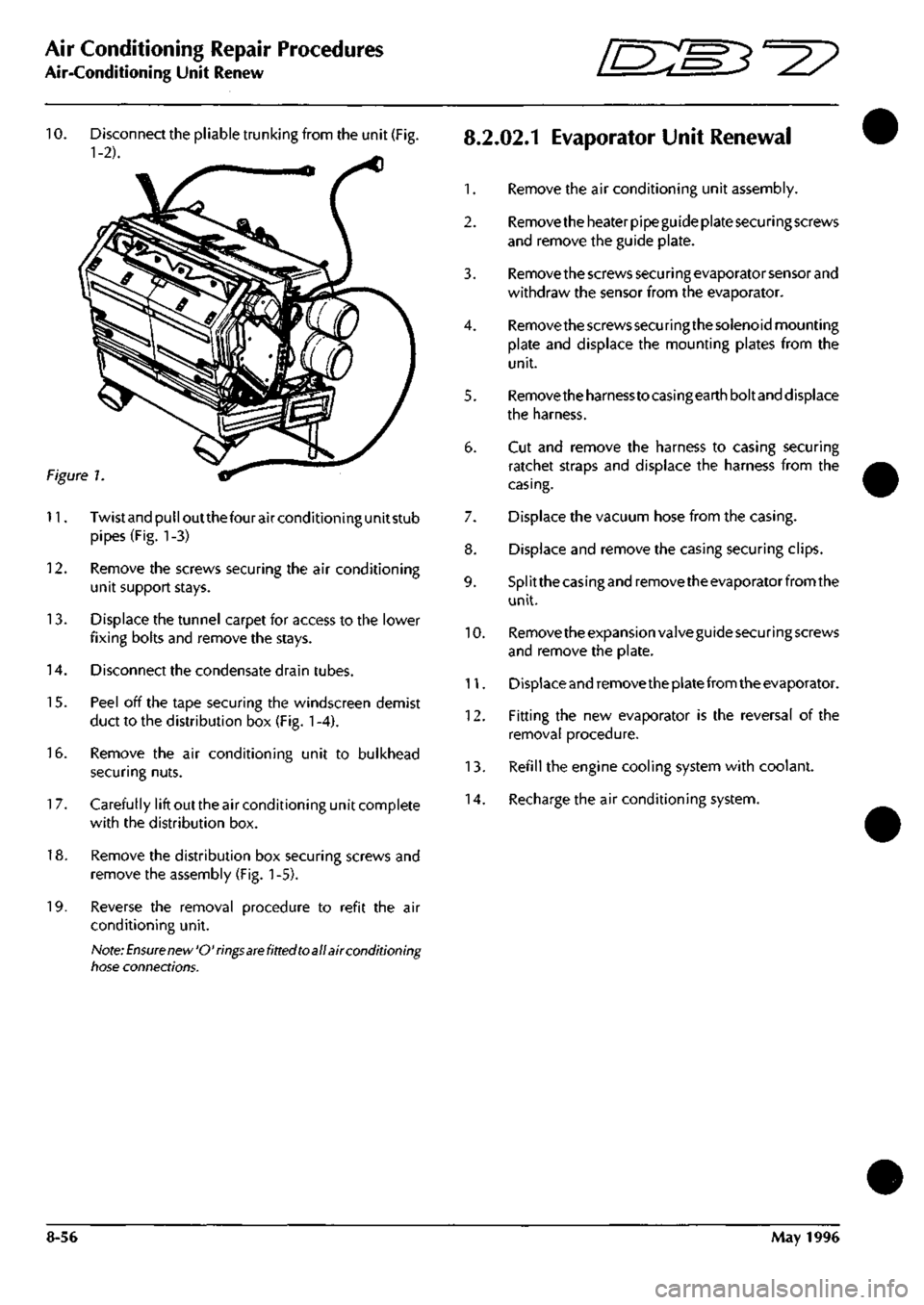
10.
Disconnect the pliable trunking from the unit (Fig.
8.2.02.1
EvaporatOr Unit Renewal
1-2). ^
1.
Remove the air conditioning unit assembly.
2.
Remove the heater pipe guide plate securing screws
and remove the guide plate.
3. Remove the screws secu ri ng evaporator sensor and
withdraw the sensor from the evaporator.
4.
Remove the screws securing the solenoid mounting
plate and displace the mounting plates from the
unit.
5. Removetheharnesstocasingearthboltand displace
the harness.
6. Cut and remove the harness to casing securing
ratchet straps and displace the harness from the
casing.
7. Displace the vacuum hose from the casing.
8. Displace and remove the casing securing clips.
9. Splitthecasingandremovetheevaporatorfromthe
unit.
10.
Remove the expansion valve guide securing screws
and remove the plate.
11.
Displace and remove the plate from the evaporator.
12.
Fitting the new evaporator is the reversal of the
removal procedure.
13.
Refill the engine cooling system with coolant.
14.
Recharge the air conditioning system.
Figure 1
11.
Twistandpulloutthefourairconditioningunitstub
pipes (Fig. 1-3)
12.
Remove the screws securing the air conditioning
unit support stays.
13.
Displace the tunnel carpet for access to the lower
fixing bolts and remove the stays.
14.
Disconnect the condensate drain tubes.
15.
Peel off the tape securing the windscreen demist
duct to the distribution box (Fig.
1
-4).
16.
Remove the air conditioning unit to bulkhead
securing nuts.
1
7. Carefully lift out the air conditioning unit complete
with the distribution box.
18.
Remove the distribution box securing screws and
remove the assembly (Fig.
1
-5).
19.
Reverse the removal procedure to refit the air
conditioning unit.
Note:
Ensure new'O'rings
are
fitted toall air conditioning
tiose connections.
8-56 May 1996
Page 336 of 421
'nzm^=2?
Air Conditioning Repair Procedures
Blower Motor Renewal
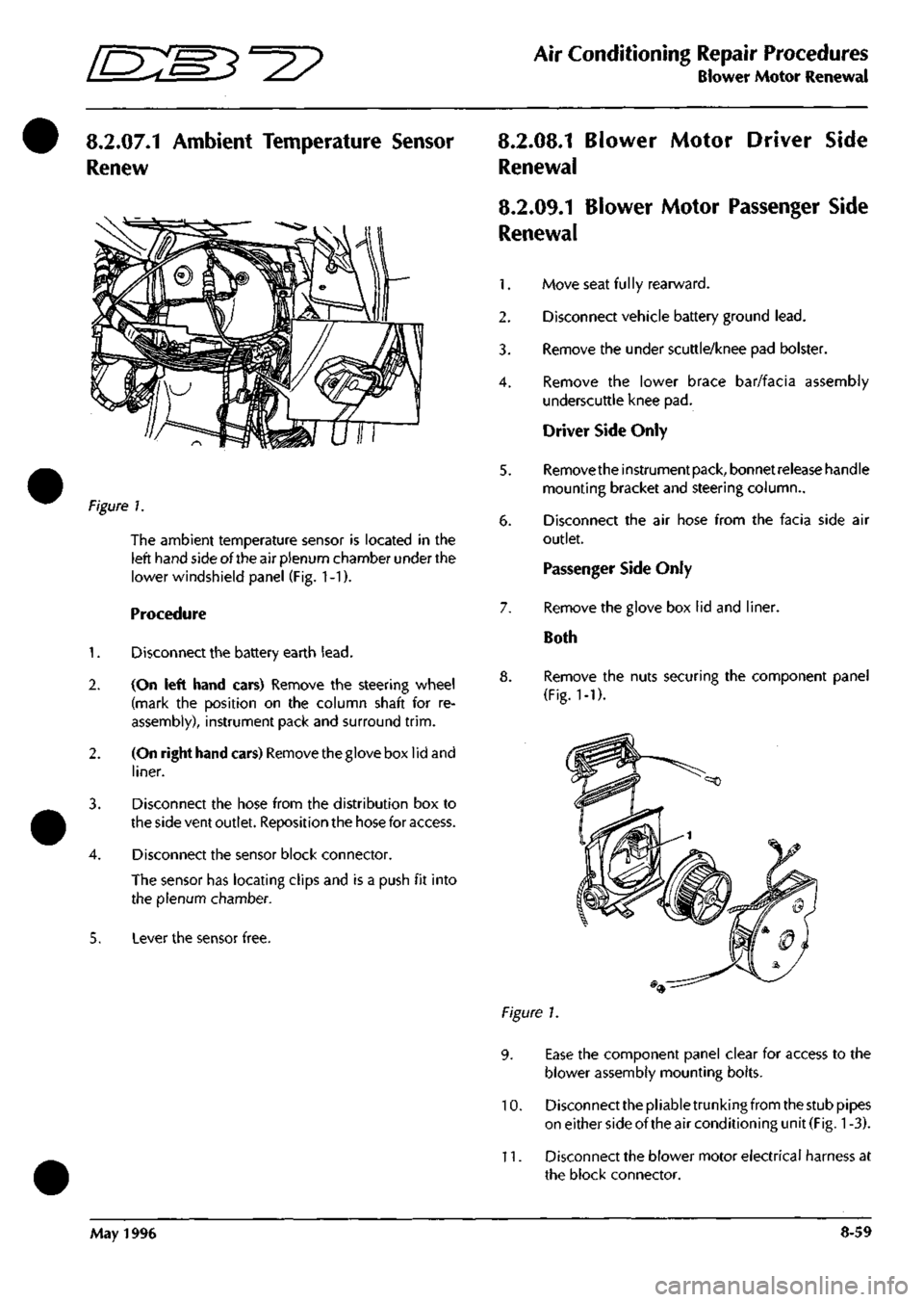
8.2.07.1 Ambient Temperature Sensor
Renew
?\gure
1.
The ambient temperature sensor is located in the
left hand side of the air plenum chamber under the
lower windshield panel (Fig. 1-1).
Procedure
1.
Disconnect the battery earth
lead.
2.
(On left hand cars) Remove the steering wheel
(mark the position on the column shaft for re
assembly), instrument pack and surround
trim.
2.
(On right hand cars) Removethegloveboxlidand
liner.
3. Disconnect the hose from the distribution box to
the side vent outlet. Reposition the hose for access.
4.
Disconnect the sensor block connector.
The sensor has locating clips and is a push fit into
the plenum chamber.
5. Lever the sensor free.
8.2.08.1 Blower Motor Driver Side
Renewal
8.2.09.1 Blower Motor Passenger Side
Renewal
1.
Move seat
fu 1
ly rearward.
2.
Disconnect vehicle battery ground
lead.
3. Remove the under scuttle/knee pad bolster.
4.
Remove the lower brace bar/facia assembly
underscuttle knee pad.
Driver Side Only
5. Removetheinstrumentpack, bonnetreieasehandle
mounting bracket and steering column..
6. Disconnect the air hose from the facia side air
outlet.
Passenger Side Only
7. Remove the glove box lid and liner.
Both
8. Remove the nuts securing the component panel
(Fig.
1-1).
Figure 1.
9. Ease the component panel clear for access to the
blower assembly mounting bolts.
10.
Disconnect the pliable trunking from the stub pipes
on either side of the air conditioning unit
(Fig.
1
-3).
11.
Disconnect the blower motor electrical harness at
the block connector.
May 1996 8-59
Page 342 of 421
Air Conditioning
Air-Conditioning Diagnostics
The Air Conditioning System Diagnostics
The air-conditioning control module (A/CCM) is located at the right end of the air-conditioning unit.
A
digital microprocessor within the
A/CCM
receives
data
signals from
the
operator controlled
switches.
Comparison
of these signals with those returned from the system temperature sensor and feedback devices results in the
appropriate voltage changes necessary to vary: blower motor
speed,
flap positions and system solenoids to respond
to the drivers selected temperature demand.
The air from the two blower motors is passed through the evaporator matrix which, depending on the A/C mode
selected,
removes heat from the incoming air. Depending on the position of
the
two blend
flaps,
the cold air passes
either directly into the vehicle outlet vents, or is passed through the heater matrix to be reheated and then passed
to the vehicle outlet vents.
The amount of air passing through the heater matrix is infinitely variable depending on ambient temperature and
the temperature selected within the vehicle.
Air Conditioning Diagnostics
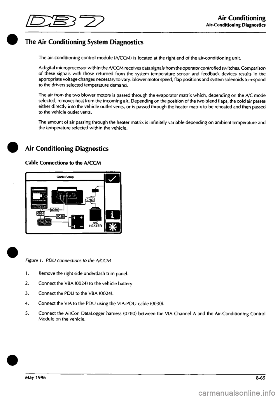
Cable Connections to the A/CCM
Cable Setup
Figure 1. PDU connections to the A/CCM
1.
Remove the right side underdash trim panel.
2.
Connect the VBA (0024) to the vehicle battery
3. Connect the PDU to the VBA (0024).
4.
Connect the VIA to the PDU using the VIA-PDU cable (0030).
5. Connect the AirCon Datalogger harness (0780) between the VIA Channel A and the Air-Conditioning Control
Module on the vehicle.
May 1996 8-65
Page 343 of 421
Air Conditioning
Portable Diagnostic Unit - Signal Monitoring 3^^?
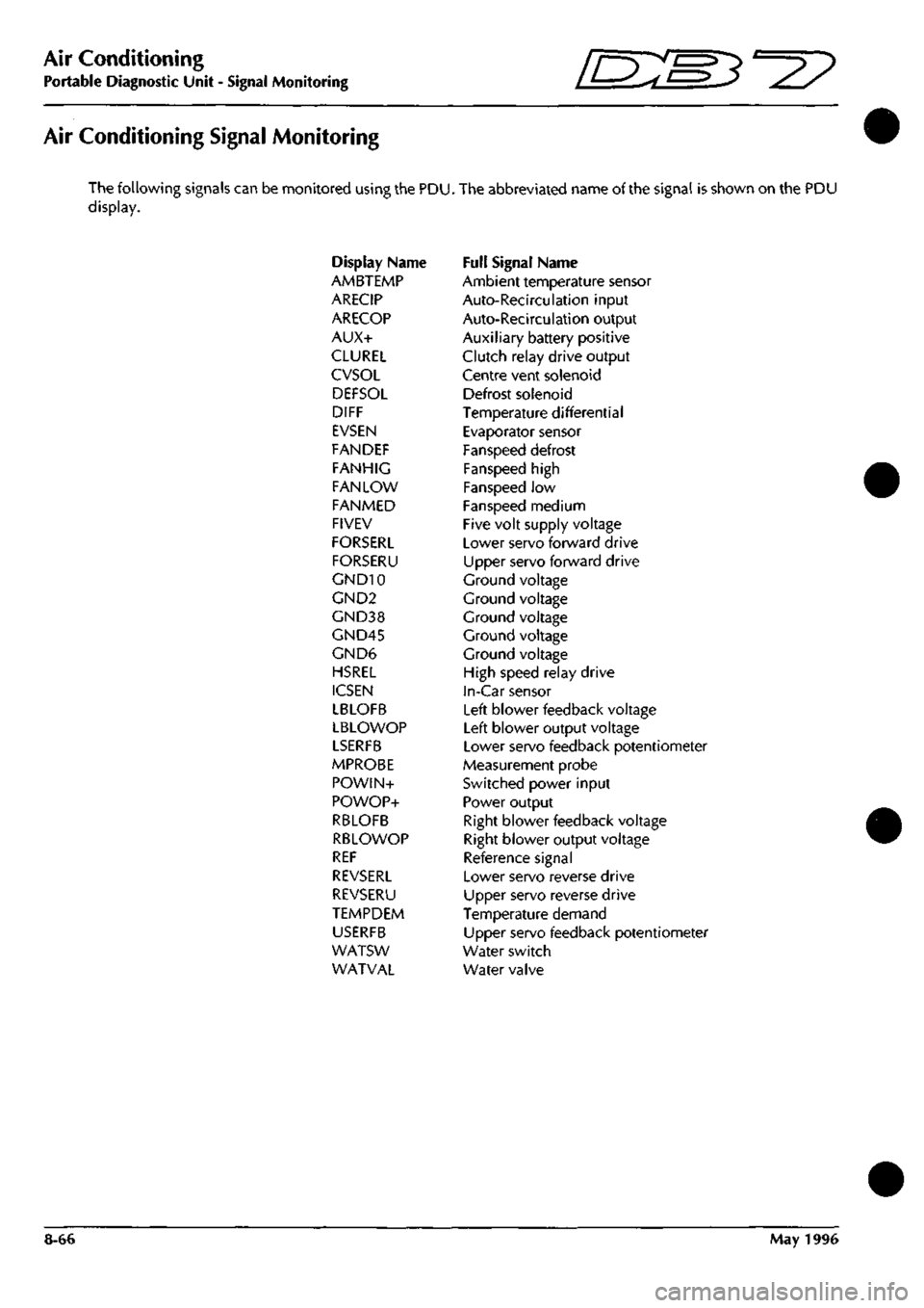
Air Conditioning Signal Monitoring
The following signals can be monitored using the PDU. The abbreviated name of the signal is shown on the PDU
display.
Display Name Full Signal Name
AMBTEMP Ambient temperature sensor
ARECIP Auto-Recirculation input
ARECOP Auto-Recirculation output
AUX+ Auxiliary battery positive
CLUREL Clutch relay drive output
CVSOL Centre vent solenoid
DEFSOL Defrost solenoid
DIFF Temperature differential
EVSEN Evaporator sensor
FANDEF Fanspeed defrost
FANHIG Fanspeed high
FAN LOW Fanspeed low
FANMED Fanspeed medium
FIVEV Five volt supply voltage
FORSERL Lower servo forward drive
FORSERU Upper servo forward drive
GND10 Ground voltage
GND2 Ground voltage
GND38 Ground voltage
GND45 Ground voltage
GND6 Ground voltage
HSREL High speed relay drive
ICSEN In-Car sensor
LBLOFB Left blower feedback voltage
LBLOWOP Left blower output voltage
LSERFB Lower servo feedback potentiometer
MPROBE Measurement probe
POWIN+ Switched power input
POWOP+ Power output
RBLOFB Right blower feedback voltage
RBLOWOP Right blower output voltage
REF Reference signal
REVSERL Lower servo reverse drive
REVSERU Upper servo reverse drive
TEMPDEM Temperature demand
USERFB Upper servo feedback potentiometer
WATSW Water switch
WATVAL Water valve
8-66 May 1996