air conditioning ASTON MARTIN DB7 1997 Manual Online
[x] Cancel search | Manufacturer: ASTON MARTIN, Model Year: 1997, Model line: DB7, Model: ASTON MARTIN DB7 1997Pages: 421, PDF Size: 9.31 MB
Page 348 of 421
Air Conditioning
Portable Diagnostic Unit - Signal Definitions
Left Blower Feedback Voltage
(LBLOFB)
Left Blower Output Voltage
(LBLOWOP)
pin 22 = 5±1 volt
pin22 = 9±lvolt
pin 22 = 5±1 volt
pin 22 = 2±1 volt
pin22 = 6±1volt
pin 22 = 2±1 volt
A/CCM Pin 22 ref Pin 6
This signal informs the control module of the present voltage applied to the left
blower. The control module can then monitor and vary this voltage to change
blower motor speed. With Manual selected, the blower operates in four basic
ranges:
Low Speed
Temp Min:
Temp Med:
Temp Max:
Medium Speed
Temp Min:
Temp Med:
Temp Max:
High Speed
Pin 22 = 1±1 volt at all temperature settings
Defrost
Pin 22 = 1±1 volt at all temperature settings
A/CCM Pin 31 ref Pin 6
This signal is produced by the control moduleto drive the blower motor. The signal
can vary from 0-3 volts depending on blower motor
speed.
The higher the voltage,
the higher the blower motor speed. This signal is amplified by a simple amplifier
circuit inside the blower motor. This circuit also supplies the feedback signals to
pins 22 and 33.
Note: If the signal
rises
above 5
volts,
then
suspect a
fault in the amplifier circuit.
Lower Servo Feedback Potentiometer
(LSERFB) A/CCM Pin 29 ref Pin 6
This feedback signal informs the control module of the exact position of the flaps,
enabling accurate control of flap position.
Defrost - Lower flap signal should be 2.9 volts (flap closed) upper flap signal
should read 1.9 volts.
Max Temp - Lower flap signal should read 1.14 volts, upper flap signal should
read 1.9 volts.
Min Temp- Both lower and upper flap signals should read 130± 80 millivolts.
Note: If the
feedback sticks
low, with the fan continually running,
suspect an
open circuit
in the 5 volts supply to the
feedback
potentiometer or
the
potentiometer
itself.
May 1996 8-71
Page 349 of 421
Air Conditioning
Portable Diagnostic Unit Signal Definitions ~3^^?
Measurement Probe
(MPROBE)
Switched Power Input
(POWIN+)
Power Output
(POWOP+)
Right Blower Feedback Voltage
(RBLOFB)
Right Blower Output Voltage
(RBLOWOP)
Measurement probe (RED) with reference to measurement probe (BLACK).
A/CCM Pin 44 ref Pin 6
Switched power-in is a signal from the control module. Unlike the unswitched
power available on pins 1 and 12, this signal is only available when the A/C is
switched on.
A/CCM Pin 12 ref vehicle battery +ve
This is the ignition power for the whole A/C system. It passes through the A/CCM
via pins 1 and 12 (and a feedback protection diode) before supplying the fan
control switch. Pin 12 should normally read battery voltage with the ignition
switch in positions I or
II.
With the ignition switch off, pin 12 should read 0 volts.
A/CCM Pin 33 ref Pin 6
The purpose of the blower feedback is to inform the control module of the present
blower speed. This enables the control module to directly monitor and control
blower motor speed. With Manual selected, the blower operates in four basic
ranges:
Low Speed
Temp Min:
Temp Med:
Temp Max:
Medium Speed
Temp Min:
Temp Med:
Temp Max:
High Speed
Pin 33 = 1±1 volt at all temperature settings
Defrost
Pin 33 = 1±1 volt at all temperature settings
pin 33 = 5±1 volt
pin 33 = 9±1volt
pin 33 = 5±1 volt
pin 33 = 2±1 volt
pin 33 = 6±1volt
pin 33 = 2±1 volt
A/CCM Pin 32 ref Pin 6
This signal is produced by the control module to drive the blower motor. The signal
can vary from 0-3 volts depending on blower motor
speed.
The higher the voltage,
the higher the blower motor speed. This signal is amplified by a simple amplifier
circuit inside the blower motor. This circuit also supplies the feedback signals to
pins 22 and 33.
Note: If
the
signal
rises
above 5 volts, then
suspect a
fault in the amplifier circuit.
8-72 May 1996
Page 350 of 421
O" D'^?
Air Conditioning
Portable Diagnostic Unit - Signal Definitions
Reference Signal
(REF) A/CCM Pin 7 ref Pin 6
This is the main reference signal for the A/CCM. All the sensors reference against
this voltage. Drift in this signal will cause inconsistent temperature control.
Normal voltage should read 2.885 ±10 millivolts
Temperature Demand
(TEMPDEM)
Temperature demand control either selects the required temperature of the system
(auto mode) or the outlet temperature of the vents (manual mode). Pin 35 will vary
from 0 volts at full cooling up to 2.885 volts at full heating.
Note: When
defrost is
selected,
the
signal at pin 35
is
ignored.
The system
will go into full
heating through the upper flaps
only.
Upper Servo Feedback Potentiometer
(USERFB) A/CCM Pin 30 ref Pin 6
The feedback signal informs the control module ofthe exact position of the flaps,
enabling accurate control ofthe flap position.
Defrost - Lower flap signal should read 2.9 volts (flap closed, the upper flap
signal should read 1.9 volts.
Max Temperature - Lower flap signal should read 1.14 volts, upper flap signal
should read 1.9 volts.
Min Temperature - Both upper and lower flap signals should read
1
30 ±80
millivolts.
Note: If the
feedback sticks
low, with the
fan
continually running,
suspect an
open circuit
in the 5 volt supply to the feedback potentiometer or the potentiometer itself
Water Switch
(WATSW)
Water Valve
(WATVAL)
A/CCM Pin 21 ref Pin 6
The water switch monitors the temperature ofthe coolant and inhibits heating by
restricting fan operation at coolant temperatures below 30 degrees Celsius. This
enables the vehicle to warm up at a faster rate. It can be overridden by selecting
Defrost.
A/CCM Pin
1
7 ref Pin 6
The water valve controls thef low of hot coolant to the heater matrix. When manual
full cooling is selected, the valve will close inhibiting the heating effort ofthe
matrix, thus enhancing the cooling effect
Full cooling selected; pin
1
7 should read 10+volts and the water valve should be
closed.
All other conditions, pin
1
7 should read below 0.5 volts and the water valve should
be open.
May 1996 8-73
Page 351 of 421

Air Conditioning
[Dm^'^2?
8-74 May 1996
Page 379 of 421
The Aston Martin Lagonda Diagnostic System
Users Guide o: "3^^?
PDU Functions
The PDU main menu provides access into the following functions:
Diagnostics
Training
Digital Multimeter
User Self Test
Diagnostics
On selecting'Diagnostics'from the main
menu,
the user will be prompted to enter the features and market specification
of the vehicle to be tested. Use of the diagnostics in each of the above areas is described later in this guide.
Diagnostics Menu - 95 Model Year
Engine
Anti-Lock Braking System
Vlenu - 97 Model Year
Engine Diagnostics
OBD II Scan Tool
Airbag
Seat Belt Pretensioner
•
•
•
•
Transmission
Engine Datalogger
Climate Control
PATS System
Climate Control
Transmission
Anti-Lock Braking System
Security
Digital Multimeter
The Digital Multimeter function provides the capabilityto measure voltage, current, resistance, frequency, pulse width,
pulse period, and duty cycle. These measurements are usually made using the PDU measurement probes. Measurements
may also be made using the module pin selection function on the Teves Mk
II
braking system and on the Air Conditioning
system.
Training
An on-screen programme is provided to train new users in the use of screen icons and in the use of the digital multi
meter and datalogger functions.
User Self Test
In order to prove that the equpment is functioning correctly, a complete user self test is incorporated. The user is directed
to test the PDU and then to progressively connect each part of the PDU system which will be tested by the software.
Any fault identified during the test is notified to the user. If no faults are identified, the user is advised on the correct
functioning of the system.
PDU Power
Power for the PDU is supplied via an internal rechargeable battery pack which can keep the PDU operational for
approximately one hour when disconnected from the base station and the vehicle. In order to preserve PDU battery
charge, power to the screen backlight is automatically cut after five minutes of inactivity. The power ON indicator
remains lit, indicating that the PDU is in 'stand-by' mode. One touch of the screen will restore backlight power.
When connected to the base station, power is supplied to the PDU from the Electronic Module to recharge the PDU
battery pack as necessary.
On 95 MY vehicles, the Vehicle Battery Adaptor (VBA) is used to maintain PDU power.
On 97 MY vehicles, when connected via the MPA to either diagnostic socket on the vehicle, power is supplied via pin
4 (chassis ground) and pin 16 (battery power) to maintain PDU power at all times even when the vehicle ignition is
switched off.
On all model years, when connected to the air conditioning system using the VIA, the vehicle battery adaptor (VBA)
must also be used to maintain PDU power.
9-28 September 1996
Page 380 of 421
^=2?
The Aston Martin Lagonda Diagnostic System
Users Guide
Software
Software for the PDU system is supplied on CD ROM
discs and supports diagnosis on the following control
units:
Zytek Engine Management System (95 MY)
EEC-V Engine Management System (97 MY)
CM 4L80-E Transmission Controller
PATS - Passive Anti Theft System
Teves Mk II ABS System (95 MY)
Teves Mk IV ABS System (97 MY)
Valeo Air Conditioning System
PMC Airbag System
Megamoss Security System
Autoliv Drivers Seat Belt Pretensioner
(where fitted)
All of these systems are supported in English, French,
Italian,
German and Japanese.
In addition to the specific system software listed above,
thePDU isalsoequipped with general purpose software
to provides multimeter, printing and PDU training
options.
Software for 95 and 97 Model Year Vehicles
Software for both the 95 and 97 model year vehicles is
provided.
The PDU system requires a Vehicle Interface Adaptor
(VIA) to communicate with the control units of 95
model year vehicles.
Communication with 97 model year control units is
principally via an Aston Martin multi-protocol adaptor
to 2 inbuilt diagnostic sockets in the vehicle. Only the
air conditioning unit requires the VIA on 97 model year
vehicles.
If the multimeter function is used, the Vehicle Battery
Adaptor (VBA) will be required to provide the basic
supply and ground levels for the multimeter.
Software Loading and Selection
Ensure that the system is powered up and that the PDU is
correctly connected to the base station. Check and if
necessary load the DB7 software CD Revision 002. (see
the installation guide)
Switch 'on' the PDU which will run through two front
screens and then load the following initial PDU software.
Operating System
Main Menu
Selector
Digital Multimeter
Interactive Training
September 1996 9-29
Page 381 of 421
The Aston Martin Lagonda Diagnostic System
Users Guide D-^?
Vehicle Features
The vehicle features screen illustrated below is used to
identify the vehicle particulars and the model year.
If Airbag - NO is selected, the vehicle is assumed to be 95
model year.
If Airbag - YES is selected, 97 model year is assumed. On
completing entries in the vehicle features screen, the
appropriate vehicle area screen will be displayed.
Vehicle Features
Transmission MANUAL IIBIE^^I
Airbag IDS^I NO
D
Vehicle Area
This screen allows selection of the vehicle system to be
accessed.
Only 4 systems may be accessed on 95 model
year vehicles, on 97 model year cars, 8 systems may be
accessed as follows:
Vehicle Areas
• Engine Diagnostic
• Engine Datalogger
• Transmission
• OBDII Scan Tool
• Climate Control
• Anti-Lock Braking System
• Airbag
. lb Axol
o
PI
mLM
n
WLM
El
Ku^
95 model year software
Zytek Engine Management
GM 4L80-E Transmission Controller
Teves Mk II Anti-Lock Braking System
Valeo Air Conditioning
97 model year software
EEC-V Engine Management
CM 4L80-E Transmission Controller with OBDII
Teves Mk IV Anti-Lock Braking System
Valeo Air Conditioning
PATS Engine Immobiliser
Megamoss security system
FMC Airbag system
Autoliv seatbelt pretensioner
9-30 September 1996
Page 382 of 421
^?
The Aston Martin Lagonda Diagnostic System
Users Guide
Cable Setup - 95 MY
On
selectingthe
required
vehiclearea,
the selected
software
will be loaded and then the Cable Setup screen will
appear.
Connections will
be
shown directly
to the selected
control
unit
on
95 nnodel year vehicles
using
the vehicle interface
adaptor (VIA) and appropriate cables from the PDU kit.
Select the specified interface devices and cables from the
PDU kit and connect as shown in the diagram.
Cable Setup - 97 MY
On 97 model year
vehicles,
connections
to the
vehicle are
made via the Aston Martin Multi-Protocol Adaptor and
two diagnostic sockets for most vehicle systems.
Cable Setup
Upper Diagnostic Socket
o
Diagnostic Sockets - 97 MY
The diagnostic sockets are located behind the passenger
side underscuttle panel.
Upper Diagnostic Socket
Lower Diagnostic Socket
The
sockets are
mounted on
a
bracket
and
labelled Upper
and Lower. The following lists describe the systems
accessed from each socket.
Upper Diagnostic Socket
Transmission Control Module (TCM)
Megamoss Security System
FMC Airbag System
Teves Mk IV Anti-Lock Braking System
Lower Diagnostic Socket
EEC V Powertrain Control Module (PCM)
PATS Passive Anti-Theft System
Autoliv Seatbelt Pretensioner System
Air Conditioning Diagnostics
The Valeo air-conditioning system uses a unique
communications protocol and therefore the vehicle
interface adaptor (VIA) is required and is connected
directlytotheair-conCPU inordertocarryout diagnostics
work on the system.
September 1996 9-31
Page 394 of 421
^?
The Aston Martin Lagonda Diagnostic System
Users Guide
Climate Control Diagnostics
The air conditioning control module is located at the right
end of the air conditioning unit. Since this controller uses
a unique communications protocol, the PDU must be
connected directly to the unit via the Vehicle Inerface
Adaptor as shown in the following cable setup screen.
Cable Setup
Adigitalmicroprocessorwithin the control module receives
data signals from the operator controlled switches.
Comparison of these signals with those returned from
system temperature sensors and feedback devices results
in the appropriate output voltage changes needed to vary:
Blower motor speed, flap position and the solenoids
which respond to operator selected temperature demand.
The air from two blower motors is passed through the
evaporator matrix which, depending on the positions of
the humidity buttons, removes heat from the incoming air.
Dependingon the position of the two blend flaps, the cold
air either passes directly to the vehicle outlet vents, or is
passed through the heater matrix to be reheated and then
to the vehicle outlet vents.
The amount of air passing through the heater matrix is
infinitely variable depending on ambienttemperature and
the temperature selected within the vehicle.
Selecting 'Climate Control' from the vehicle area menu,
will presentthetechnician with the dataloggertool selection
screen.
Details of the signals which may be monitored in the
system may be found in the DB7 Workshop Manual -
Section 8 - Air Conditioning'
Anti-Lock Braking Diagnostics
The Teves Mk IV Braking System consists of two sub
systems, power braking and anti-lock braking.
The PDU software(DataLogger) only allows the monitoring
of the anti-lock braking system.
The ABS System consists of:
Four wheel speed sensors.
One control module.
Seven solenoid valves.
One pressure switch.
One fluid level switch.
The ABS System
is
controlled and continuously monitored
by the ABS control module, which automatically
switchesoffthesystemifafailure is identified, illuminating
a warning lamp and leaving
full,
boosted braking to all
wheels. A wheel speed sensor is installed at each wheel.
Their wheel speed related signals are processed by the
control module, which triggers the solenoid valves to
modulate hydraulic pressure, preventing the wheels from
locking.
The control module also monitors the fluid
level and will inhibit ABS operation should lowfluid level
be detected.
The Datalogger function will permit monitoring of the
complete system apart from the solenoid valves. The
control module transmits short duration test pulses of 25
to 100 microseconds to the solenoid valves. These
pulses are too fast for the PDU to monitor and as a result
would cause confusing waveforms.
Selecting 'Anti-Lock Braking' from the vehicle area menu,
will present the technician with the following menu of
diagnostic tools screen:
Anti-Lock Brakes Diagnostic
Datalogger
Diagnostic Trouble Codes
o
ABS Diagnostic Trouble Codes
The DTCs which are supported in the Teves Mk IV ABS
system are listed in the workshop manual - Section 5
Brakes Wheels and Tyres.
September 1996 9-43
Page 401 of 421
The Aston Martin Lagonda Diagnostic System
Users Guide ^=2?
Printer Use Digital Multimeter
Print Trace
The Trace Buffer is used to record technician use of the
PDU.As the diagnostics are executed, the following
information is written to trace:
Screen Title
Menu options selected
Operator questions selected
Operator actions
Control module information
Test limits and results
P codes detected by the DTC monitor
Snapshot data from the datalogger
OBD II freeze frame data
Set up the printer and load with paper. Select Print
Trace and confirm the selection. All recorded
information in the above list will be printed.
Printtrace is supported in English, French, German and
Italian.
Print Screen
The Print Screen function dumps a bitmap image of the
current screen display to the printer. This function is
particularly useful for recordingdata such as waveforms
captured by the datalogger application.
The print screen function is supported in English,
French,
German, Italian and Japanese.
Introduction
The Digital Multi-Meterprovidesthecapability to measure
voltage, current, resistance, frequency, pulse width, pulse
period and duty cycle using measurement probes or
vehicle interface adaptor channels.
WARNING: DMM measurements must not be taken
while the PDU
is
connected to the
base
station. The PDU
measurement system
becomes
referenced to earth when
connected to the base station. Serious measurement
errors may be present
because
of any voltage difference
between vehicle ground and base station earth. Operation
of the PDU in this mode has both functional and safety
implications and therefore must be
avoided.
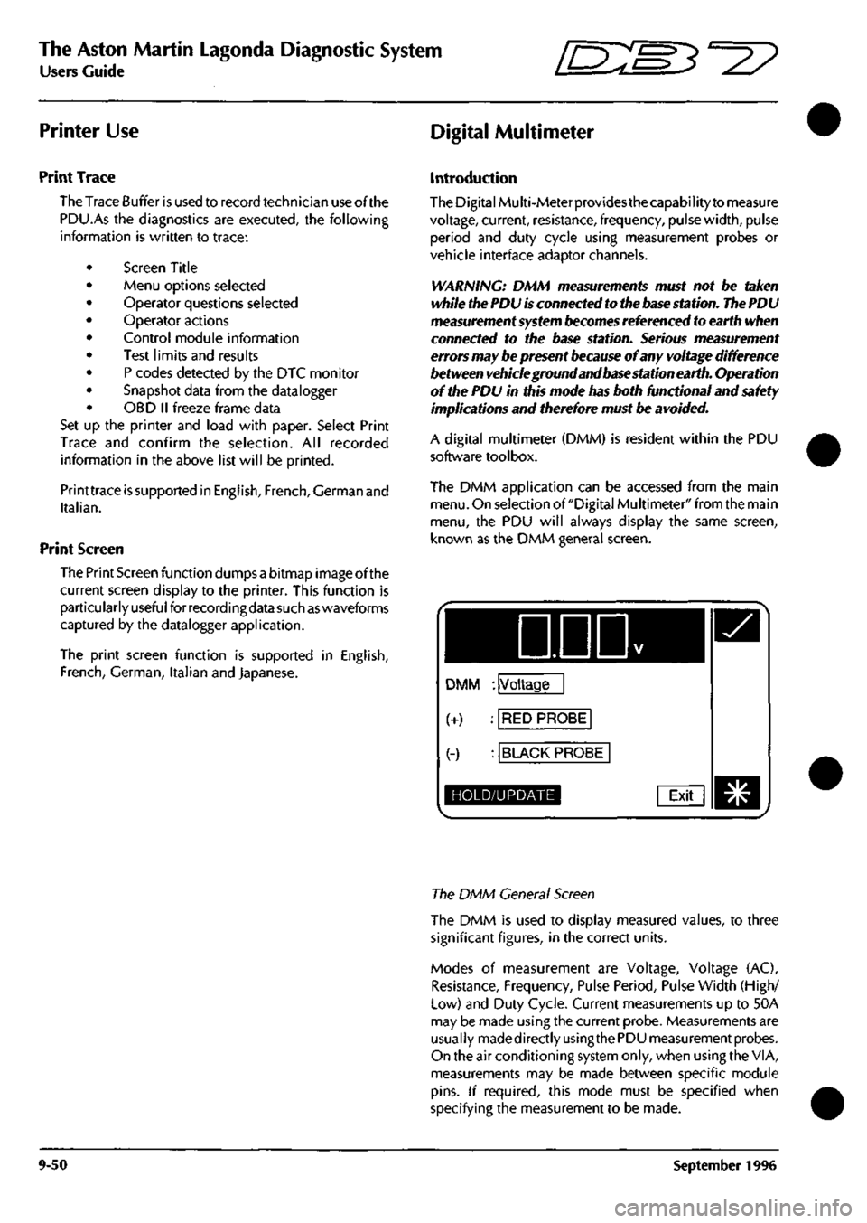
A digital multimeter (DMM) is resident within the PDU
software toolbox.
The DMM application can be accessed from the main
menu.
On selection of "Digital Multimeter" from the main
menu,
the PDU will always display the same screen,
known as the DMM general screen.
DDD
DMM : Voltage
(+) : RED PROBE
(-) : BLACK PROBE
HOLD/UPDATE Exit
The DMM General Screen
The DMM is used to display measured values, to three
significant figures, in the correct units.
Modes of measurement are Voltage, Voltage (AC),
Resistance, Frequency, Pulse Period, Pulse Width (High/
Low) and Duty Cycle. Current measurements up to 50A
may be made using the current probe. Measurements are
usually madedirectlyusingthe PDU measurement probes.
On the air conditioning system only, when using the VIA,
measurements may be made between specific module
pins.
If required, this mode must be specified when
specifying the measurement to be made.
9-50 September 1996