door lock ASTON MARTIN DB7 1997 Workshop Manual
[x] Cancel search | Manufacturer: ASTON MARTIN, Model Year: 1997, Model line: DB7, Model: ASTON MARTIN DB7 1997Pages: 421, PDF Size: 9.31 MB
Page 9 of 421
[Em^^^?
Electrics
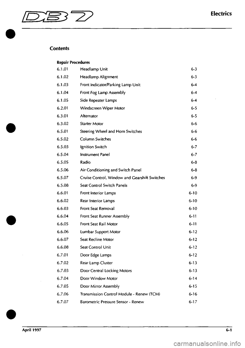
Repair Procedures
6.1.01
6.1.02
6.1.03
6.1.04
6.1.05
6.2.01
6.3.01
6.3.02
6.5.01
6.5.02
6.5.03
6.5.04
6.5.05
6.5.06
6.5.07
6.5.08
6.6.01
6.6.02
6.6.03
6.6.04
6.6.05
6.6.06
6.6.07
6.6.08
6.7.01
6.7.02
6.7.03
6.7.04
6.7.05
6.7.06
6.7.07
Headlamp Unit
Headlamp Alignment
Front Indicator/Parking Lamp Unit
Front Fog Lamp Assembly
Side Repeater Lamps
Windscreen Wiper Motor
Alternator
Starter Motor
Steering Wheel and Horn Switches
Column Switches
Ignition Switch
Instrument Panel
Radio
Air Conditioning and Switch Panel
Cruise Control, Window and Gearshift Switches
Seat Control Switch Panels
Front Interior Lamps
Rear Interior Lamps
Front Seat Removal
Front Seat Runner Assembly
Front Seat Rail Motor
Lumbar Support Motor
Seat Recline Motor
Seat Control Unit
Door Edge Lamps
Rear Lamp Cluster
Door Central Locking Motors
Door Window Motor
Door Mirror Assembly
Transmission Control Module - Renew (TCM)
Barometric Pressure Sensor - Renew
6-3
6-3
6-4
6-4
6-4
6-5
6-5
6-6
6-6
6-6
6-7
6-7
6-8
6-8
6-9
6-9
6-10
6-10
6-10
6-11
6-11
6-12
6-12
6-12
6-12
6-13
6-13
6-14
6-15
6-16
6-17
April 1997 6-1
Page 21 of 421
3^?
Electrics
Rear Lamp Cluster / Central Locking System / Door Lock Motors
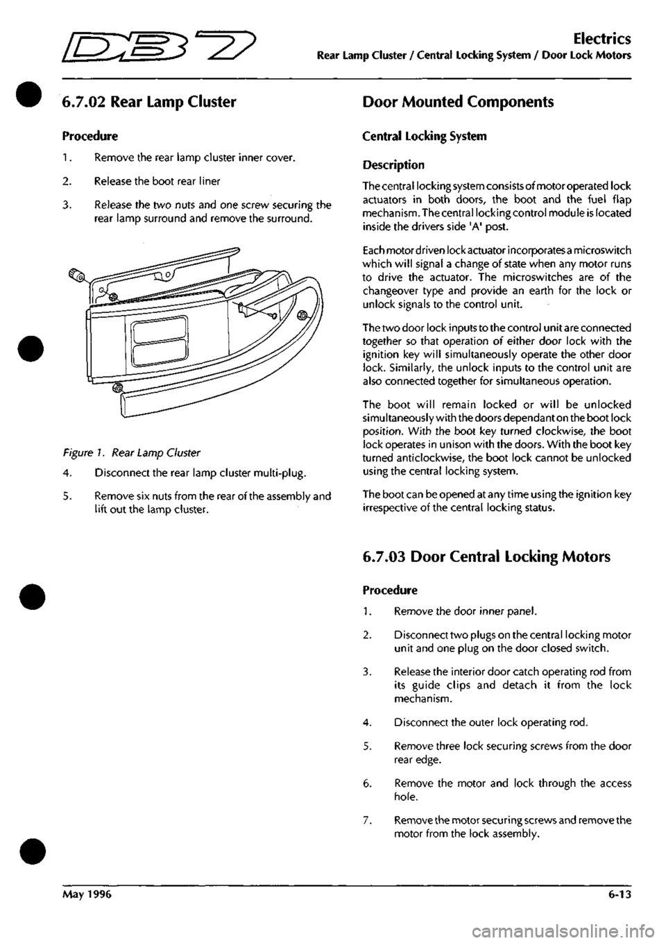
6.7.02 Rear Lamp Cluster Door Mounted Components
Procedure
1.
Remove the rear lamp cluster inner cover.
2.
Release the boot rear liner
3. Release the two nuts and one screw securing the
rear lamp surround and remove the surround.
Figure 7. Rear Lamp Cluster
4.
Disconnect the rear lamp cluster multi-plug.
5. Remove six nuts from the rear of the assembly and
lift out the lamp cluster.
Central Locking System
Description
Thecentral locking system consistsofmotoroperated lock
actuators in both doors, the boot and the fuel flap
mechanism. The central locking control module is located
inside the drivers side 'A' post.
Each motordriven lock actuator incorporatesa microswitch
which will signal a change of state when any motor runs
to drive the actuator. The microswitches are of the
changeover type and provide an earth for the lock or
unlock signals to the control unit.
The two door lock inputs to the control unit are connected
together so that operation of either door lock with the
ignition key will simultaneously operate the other door
lock. Similarly, the unlock inputs to the control unit are
also connected together for simultaneous operation.
The boot will remain locked or will be unlocked
simultaneously with the doors dependant on the boot lock
position.
With the boot key turned clockwise, the boot
lock operates in unison with the doors. With the boot key
turned anticlockwise, the boot lock cannot be unlocked
using the central locking system.
The boot can be opened at any time using the ignition key
irrespective of the central locking status.
6.7.03 Door Central Locking Motors
Procedure
1.
Remove the door inner panel.
2.
Disconnect two plugs on the central locking motor
unit and one plug on the door closed switch.
3. Release the interior door catch operating rod from
its guide clips and detach it from the lock
mechanism.
4.
Disconnect the outer lock operating rod.
5. Remove three lock securing screws from the door
rear edge.
6. Remove the motor and lock through the access
hole.
7. Remove the motor securing screws and remove the
motor from the lock assembly.
May 1996 6-13
Page 22 of 421
Electrics
Electric Windows - Fault Analysis / Window Motor Removal
[n:m3^^
Electric Windows
Description
Power to the window wind circuits is available
when the ignition switch is on and is supplied
through a thermal cut-out to the left and right
window switches. The switches are double pole
plus earth so that the current through a window
motor may be switched in either direction to raise
or lower the window.
DB7 uses frameless door windows which seal
against rubber strips around the body shell door
opening.
To avoid damaging these seals during
door opening, the door glass must be lowered
before the door can be opened. This function is
controlled by the window control units. The units
are mounted on the inside of each door frame and
will sense if a door handle is pulled to open the
door. Before releasing the door lock, the control
unit will drive the window wind motor briefly to
lower the door window glass down until it clears
the window seals. Similarly, after closing a door,
the window motor will be run to raise the door glass
to seat the glass against the body seals.
Fault Analysis Procedure
a) If a window fails to operate, check for fuse failure
and the connectors for poor or open contacts.
b) Check the thermal cut-out by shorting across it and
operating either window. If the windows operate
with the short
ci rcu
it but not without, the cut-out is
faulty.
c) With the ignition on, battery voltage should be
available between the inputterminalsof the switches
and chassis. Operate each switch and ensure that
battery voltage is available between the switch
output terminals and chassis.
d) Measure voltagefrom each switch inputterminalto
the switch earth return terminal. If no voltage is
measured,
the earth return line is open circuit.
e) Measure continuity through the wiring from the
switches to each motor. If continuity is correct,
remove the motor for bench testing.
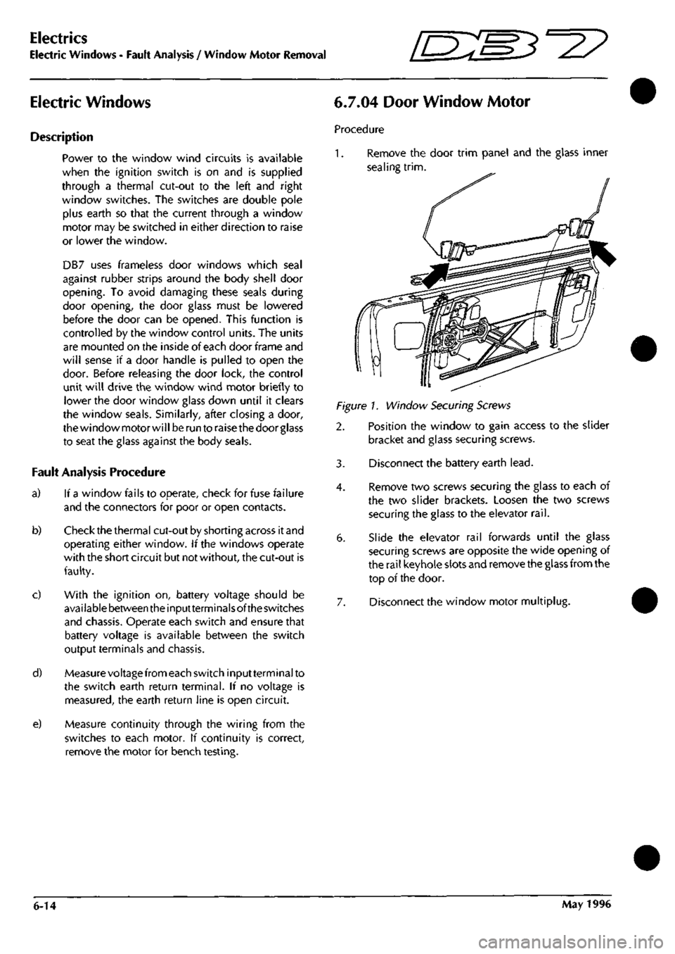
6.7.04 Door Window Motor
Procedure
1.
Remove the door trim panel and the glass inner
sealing
trim.
Figure!. Window Securing Screws
2. Position the window to gain access to the slider
bracket and glass securing screws.
3. Disconnect the battery earth
lead.
4.
Remove two screws securing the glass to each of
the two slider brackets. Loosen the two screws
securing the glass to the elevator
rail.
6. Slide the elevator rail forwards until the glass
securing screws are opposite the wide opening of
the rail keyhole slots and remove the glass from the
top of the door.
7. Disconnect the window motor multiplug.
6-14 May 1996
Page 27 of 421
Electrics
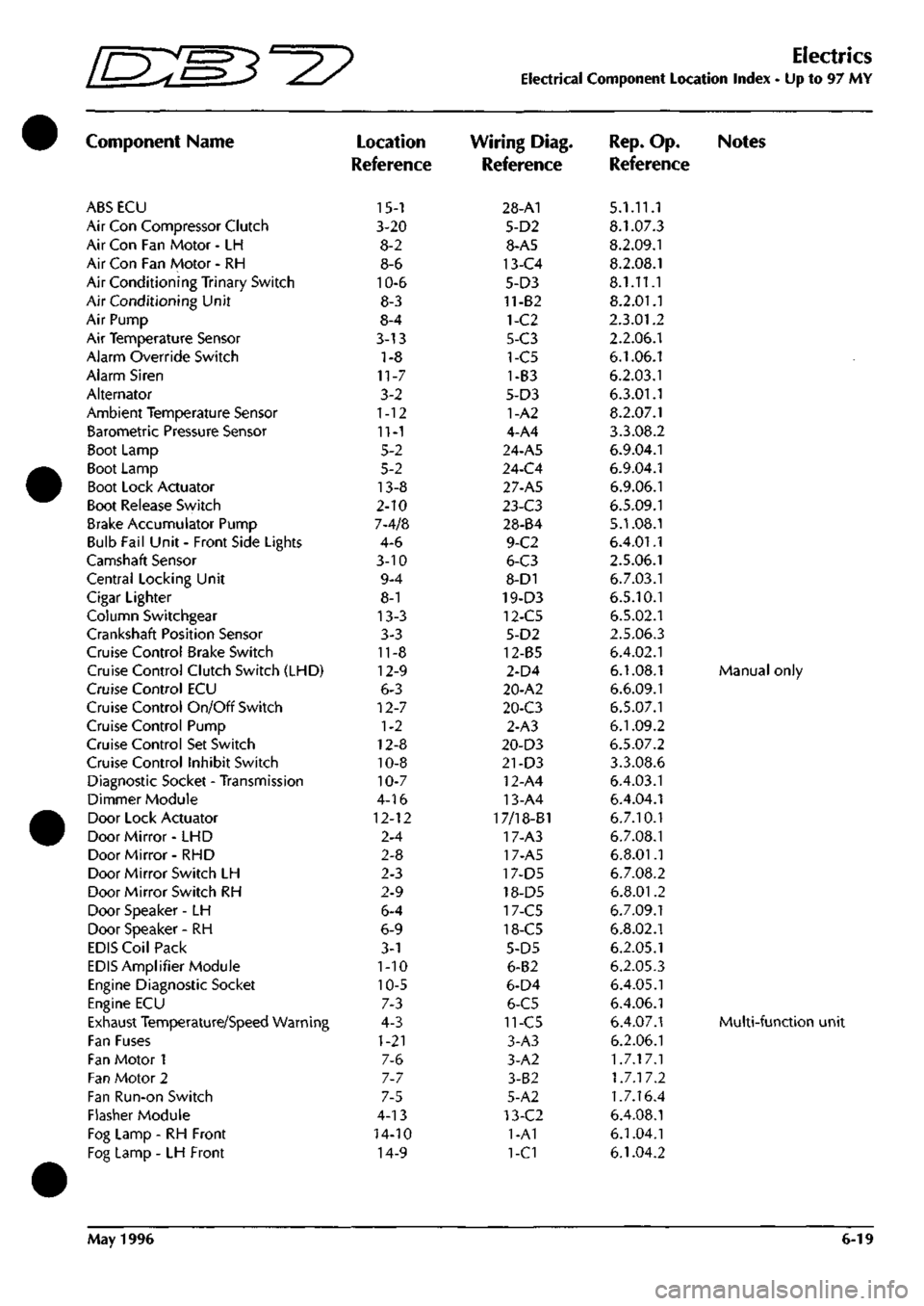
Electrical Component Location Index - Up to 97 MY
Component Name
ABS ECU
Air Con Compressor Clutch
Air Con Fan Motor - LH
Air Con Fan Motor - RH
Air Conditioning Trinary Switch
Air Conditioning Unit
Air Pump
Air Temperature Sensor
Alarm Override Switch
Alarm Siren
Alternator
Ambient Temperature Sensor
Barometric Pressure Sensor
Boot Lamp
Boot Lamp
Boot Lock Actuator
Boot Release Switch
Brake Accumulator Pump
Bulb Fail Unit - Front Side Lights
Camshaft Sensor
Central Locking Unit
Cigar Lighter
Column Switchgear
Crankshaft Position Sensor
Cruise Control Brake Switch
Cruise Control Clutch Switch (LHD)
Cruise Control ECU
Cruise Control On/Off Switch
Cruise Control Pump
Cruise Control Set Switch
Cruise Control Inhibit Switch
Diagnostic Socket - Transmission
Dimmer Module
Door Lock Actuator
Door Mirror- LHD
Door Mirror- RHD
Door Mirror Switch LH
Door Mirror Switch RH
Door Speaker -LH
Door Speaker - RH
EDIS Coil Pack
EDIS Amplifier Module
Engine Diagnostic Socket
Engine ECU
Exhaust Temperature/Speed Warning
Fan Fuses
Fan Motor 1
Fan Motor 2
Fan Run-on Switch
Flasher Module
Fog Lamp - RH Front
Fog Lamp - LH Front
Location
Reference
15-1
3-20
8-2
8-6
10-6
8-3
8-4
3-13
1-8
11-7
3-2
1-12
11-1
5-2
5-2
13-8
2-10
7-4/8
4-6
3-10
9-4
8-1
13-3
3-3
11-8
12-9
6-3
12-7
1-2
12-8
10-8
10-7
4-16
12-12
2-4
2-8
2-3
2-9
6-4
6-9
3-1
1-10
10-5
7-3
4-3
1-21
7-6
7-7
7-5
4-13
14-10
14-9
Wiring Diag.
Reference
28-A1
5-D2
8-A5
13-C4
5-D3
11-82
1-C2
5-C3
1-C5
1-B3
5-D3
1-A2
4-A4
24-A5
24-C4
27-A5
l-i-C3
28-84
9-C2
6-C3
8-D1
19-D3
12-C5
5-D2
12-85
2-D4
20-A2
20-C3
2-A3
20-D3
21-D3
12-A4
13-A4
17/18-B1
17-A3
17-A5
17-D5
18-D5
17-C5
18-C5
5-D5
6-B2
6-D4
6-C5
11-C5
3-A3
3-A2
3-B2
5-A2
13-C2
1-A1
1-C1
Rep.
Op. Notes
Reference
5.1.11.1
8.1.07.3
8.2.09.1
8.2.08.1
8.1.11.1
8.2.01.1
2.3.01.2
2.2.06.1
6.1.06.1
6.2.03.1
6.3.01.1
8.2.07.1
3.3.08.2
6.9.04.1
6.9.04.1
6.9.06.1
6.5.09.1
5.1.08.1
6.4.01.1
2.5.06.1
6.7.03.1
6.5.10.1
6.5.02.1
2.5.06.3
6.4.02.1
6.1.08.1 Manual only
6.6.09.1
6.5.07.1
6.1.09.2
6.5.07.2
3.3.08.6
6.4.03.1
6.4.04.1
6.7.10.1
6.7.08.1
6.8.01.1
6.7.08.2
6.8.01.2
6.7.09.1
6.8.02.1
6.2.05.1
6.2.05.3
6.4.05.1
6.4.06.1
6.4.07.1 Multi-functio
6.2.06.1
1.7.17.1
1.7.17.2
1.7.16.4
6.4.08.1
6.1.04.1
6.1.04.2
May 1996 6-19
Page 48 of 421
Electrics
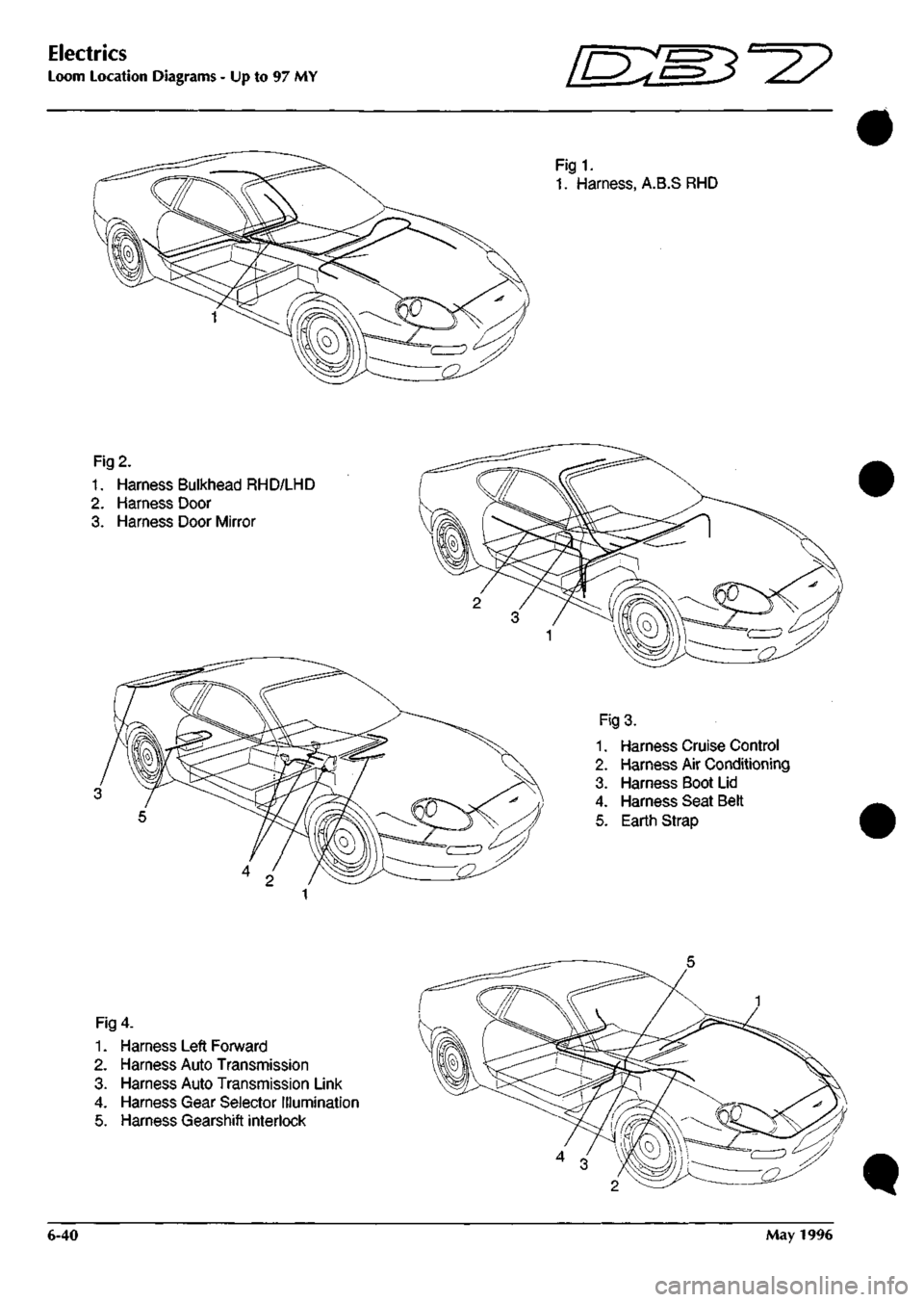
Loom Location Diagrams - Up to 97 MY in:m3'^?
Fig1.
1.
Harness, A.B.S RHD
Fig
2.
1.
Harness Bulkhead RHD/LHD
2.
Harness Door
3. Harness Door Mirror
Fig
3.
1.
Harness Cruise Control
2.
Harness Air Conditioning
3. Harness Boot Lid
4.
Harness Seat Beit
5. Earth Strap
Fig
4.
1.
Harness Left Forward
2.
Harness Auto Transmission
3. Harness Auto Transmission Link
4.
Harness Gear Selector Illumination
5. Harness Gearshift interlock
t
6-40 May 1996
Page 83 of 421

MICRO SWITCH
H4 coLduli
PIH 390 OU I 392
OR
2
I25JB
}
B?-|17I
B6
LOCK SWITCH
ffo-wroriiTr 760 B 1 761 RN 2 762
V
3 763
YG
4 764
YU
5
-imr A4-I5C
B4-M!
B5-I4! C5-I44 BS-I4S
L.H DOOR MIRROR
NO COLOUR PIN 391 OW I 389 OG 2__ B6
LOCK MOTOR
NO COLOUR PIN 755
B
1 756
RN
2 757
Y
3 758
YR
4 759
YB
5
AREA A4-I5C B4-I4! B5-I4; C5-I46 B4-I4f
tooT
SPL 151 0Q
R.H DOOR MIRROR
NO COLOUR 765
B
AREA A4-I5C B5-I47
SPL 147 SPL 145 SPL 143
1
. I .. 1
SPL 148 SPL 146 SPL 144
[amtTI'
1 13
•laD
("
c
• 0 D 0 DOZ^ D 0 D D Q 0 D 0
on:
0 D 0 D 0 Q
NO COLOUR PIN IRfF 394B I B6 395 BW 2 B6
REAR GUARD LAMP
NO COLOUR PIN 325
LG
A 768
BP
B 322
R
C 323
G
0
767
B
328
NU
AREA C6 C4-I5I
Be
B5-I47
DOOR MIRROR SWITCH
NO COLOUR 769
YR
770
YG
771 Y 752
LG
773 YU 772 B 774 YB
PIN 1 2 3 4 5 6 7
?
AREA C5-M6 C5-I44 B5-I4! C6 B5-I4! A4-I5C C4-I4f
NO COLOUR PIN 320 P 1 321 PW 2 5
AREA B6 86
NO COLOUR PIN 389 OS 390 OU 391 OW 392
OR
394 B 395 BW 320
P
321 PW 322
R
323
G
750
YG
751 YU 324
Y
752 LG 325
LG
326
NU
327
BP
328
RN
329 8 330 YR 331 YB
1 2 3 4 5 6 7 8 9 10 II 12 13 14 15 16 17 18 19 20 21 22
MS 81 A2 61 A2
C5 C5 D2 02 03 03 C5-I44 B5-I4: B5-I4; DS 03 03 C4-I5I C4-I4S B5-I4; C5-I46 C4-I4(
SHEET
8
AREA
C3
lD:m^'=2? Wiring Diagram
Model - Aston Martin DB7 Coupe
Harness Title - Passengers Door
PartNo.-B37-81312
Revision - 0 Sheet 17 of 29 - Up to 97 MY
Page 85 of 421

HO COLOUR
PIH
&RE7
776
BP I
04-160
777
B
2 M-159 2
MICRO SWITCH
LOCK SWITCH
HO C6L6illl 760 B 761
RN
762
r 765 rc
764
YU
I^IN
1 2 3 4
}
,.
AREA A4-I5S B4-I5( 85-152 C5-I55 BS-154
L.H
DOOR MIRROR NO COLOUR 755
B
756
RH
757
1
758
VR
'59
YB
r-
1
AREA A4-I59 B4-I58 B5-I52 C5-I55
B1-I5]
SPL 160
-
HO COLOUR
PIH
690 OW
I
688 OG
2
AREA B6 86
OCD
R.H
DOOR MIRROR
NO COLOUR AREA 765
B
A4-I59 766
B
B5-I56
SPL
156 SPL 154 SPL 152
1.1.1
SPL
157 SPL 155 SPL 153
-[iBQlllDs
1
15
^0
D
l»
c
a
D
D
0
ooz^
0
0
Q
Q
0
D
0
D
onzr'
Q
0
Q
0
0
Q
NO MI.6UA ^IM JRfT
693 B
1 B6
694 BW
2 B£_
REAR GUARD LAMP
NO COLOUR 698 LG 768
BP
548 R 549 6
767
B
699 HU
Pita
A B C D E F
?
AREA C6 C4-I60 B6 66
B5-I56 C6
DOOR MIRROR SWITCH
HO COLOUR 769
VR
770
YG
771
Y
697 LG 773 YU 772
B
774 YB
PIN 1 2 3 4 5 6 7
8
AREA C5-I55 05-153 85-152 06 B5-I5< A4-I5S 04-157
HO COLOUR
PIN
695 P
I 696
PW
2
3
AREA
86 86
NO COLOUR
PIH
688 OG 689 OU 690 OW 691
OR
695 B 694 BW 695 P 696 PW 548 R 549 G 753
YG
754
YU
324
Y
697 LG 698 LG 699 NU 700 BP 701
RN
702
B
330 YR 331
YB
1 2 3 4 5 6 7 8 9 10 II 12 13 14 15 16 17 18 19 20 21
22-
•/SREr
Bl A2 Bl Bl
A2 05 D2 02 02 D3 03-153 C5-I54 B5-152 D5 03 03 C4-16( C4-158 B5-156 05-155 04-157
Wiring Diagram
Model
-
Aston Martin
DB7
Coupe
Harness Title
-
Drivers Door
PartNo.-B37-81313
Revision
- 0
Sheet
18 of 29 - Up to 97 MY
Page 108 of 421
^7
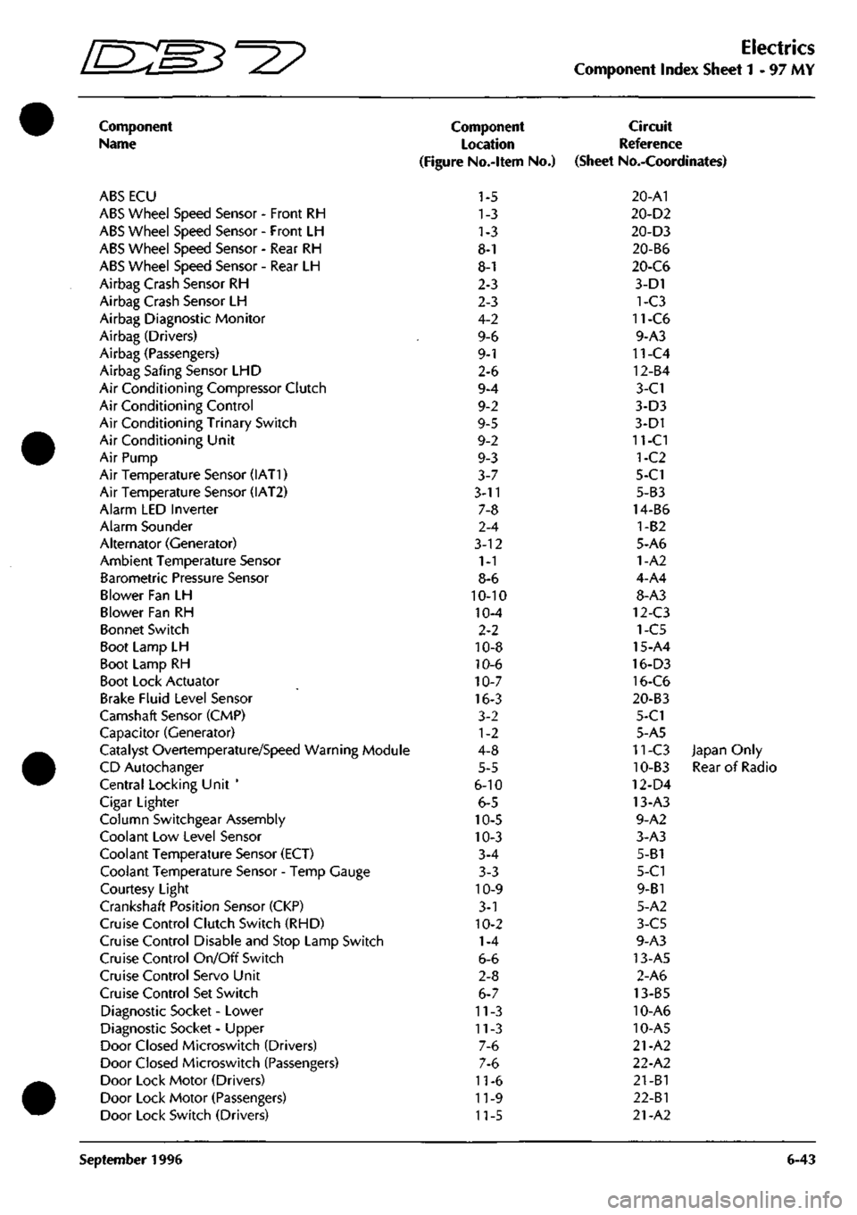
Electrics
Component Index Sheet 1-97 MY
Component
Name
ABS ECU
ABS Wheel Speed Sensor - Front RH
ABS Wheel Speed Sensor - Front LH
ABS Wheel Speed Sensor - Rear RH
ABS Wheel Speed Sensor - Rear LH
Airbag Crash Sensor RH
Airbag Crash Sensor LH
Airbag Diagnostic Monitor
Airbag (Drivers)
Airbag (Passengers)
Airbag Safing Sensor LHD
Air Conditioning Compressor Clutch
Air Conditioning Control
Air Conditioning Trinary Switch
Air Conditioning Unit
Air Pump
Air Temperature Sensor (IAT1)
Air Temperature Sensor (IAT2)
Alarm LED Inverter
Alarm Sounder
Alternator (Generator)
Ambient Temperature Sensor
Barometric Pressure Sensor
Blower Fan LH
Blower Fan RH
Bonnet Switch
Boot Lamp LH
Boot Lamp RH
Boot Lock Actuator
Brake Fluid Level Sensor
Camshaft Sensor (CMP)
Capacitor (Generator)
Catalyst Overtemperature/Speed Warning Module
CD Autochanger
Central Locking Unit '
Cigar Lighter
Column Switchgear Assembly
Coolant Low Level Sensor
Coolant Temperature Sensor (ECT)
Coolant Temperature Sensor - Temp Gauge
Courtesy Light
Crankshaft Position Sensor (CKP)
Cruise Control Clutch Switch (RHD)
Cruise Control Disable and Stop Lamp Switch
Cruise Control On/Off Switch
Cruise Control Servo Unit
Cruise Control Set Switch
Diagnostic Socket - Lower
Diagnostic Socket - Upper
Door Closed Microswitch (Drivers)
Door Closed Microswitch (Passengers)
Door Lock Motor (Drivers)
Door Lock Motor (Passengers)
Door Lock Switch (Drivers)
Component
Location
(Figure No.-ltem No.)
1-5
1-3
1-3
8-1
8-1
2-3
2-3
4-2
9-6
9-1
2-6
9-4
9-2
9-5
9-2
9-3
3-7
3-11
7-8
2-4
3-12
1-1
8-6
10-10
10-4
2-2
10-8
10-6
10-7
16-3
3-2
1-2
4-8
5-5
6-10
6-5
10-5
10-3
3-4
3-3
10-9
3-1
10-2
1-4
6-6
2-8
6-7
11-3
11-3
7-6
7-6
11-6
11-9
11-5
Circuit
Reference
(Sheet No.-Coordinates)
20-A1
20-D2
20-D3
20-B6
20-C6
3-D1
1-C3
11-C6
9-A3
11-C4
12-B4
3-C1
3-D3
3-D1
11-CI
1-C2
5-C1
5-B3
14-B6
1-B2
5-A6
1-A2
4-A4
8-A3
12-C3
1-C5
15-A4
16-D3
16-C6
20-B3
5-C1
5-A5
11-C3 Japan Only
10-B3 Rear of Radio
12-D4
13-A3
9-A2
3-A3
5-B1
5-C1
9-B1
5-A2
3-C5
9-A3
13-A5
2-A6
13-B5
10-A6
10-A5
21-A2
22-A2
21-B1
22-Bl
21-A2
September 1996 6-43
Page 109 of 421
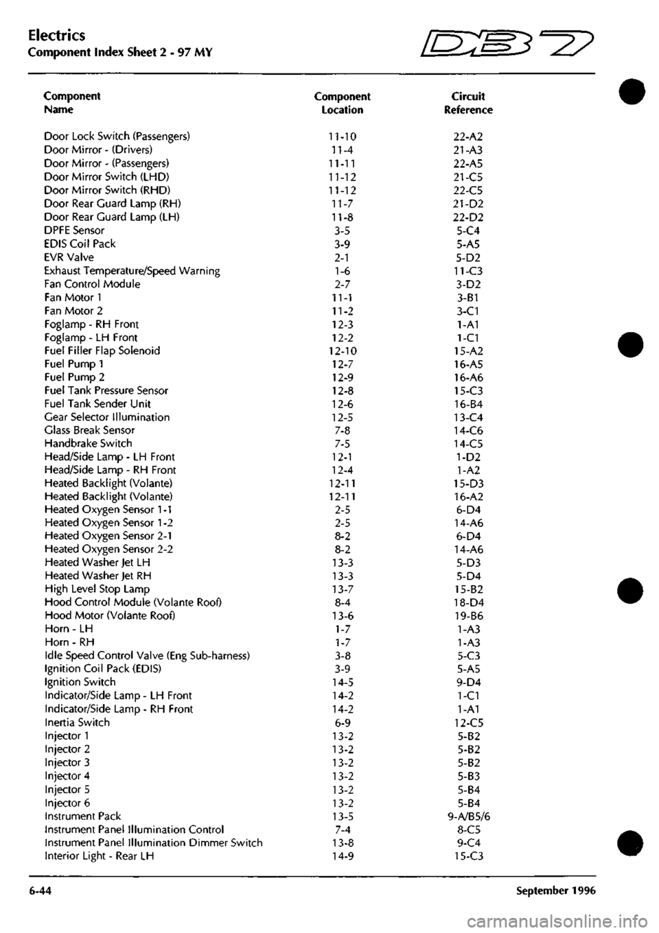
Electrics
Component Index Sheet 2 - 97 MY
Component
Name
Door Lock Switch (Passengers)
Door Mirror - (Drivers)
Door Mirror - (Passengers)
Door Mirror Switch (LHD)
Door Mirror Switch (RHD)
Door Rear Guard Lamp (RH)
Door Rear Guard Lamp (LH)
DPFE Sensor
EDIS Coil Pack
EVR Valve
Exhaust Temperature/Speed Warning
Fan Control Module
Fan Motor 1
Fan Motor 2
Foglamp - RH Front
Foglamp - LH Front
Fuel Filler Flap Solenoid
Fuel Pump 1
Fuel Pump 2
Fuel Tank Pressure Sensor
Fuel Tank Sender Unit
Gear Selector Illumination
Glass Break Sensor
Handbrake Switch
Head/Side Lamp - LH Front
Head/Side Lamp - RH Front
Heated Backlight (Volante)
Heated Backlight (Voiante)
Heated Oxygen Sensor
1
-1
Heated Oxygen Sensor
1
-2
Heated Oxygen Sensor 2-1
Heated Oxygen Sensor 2-2
Heated Washer Jet LH
Heated Washer Jet RH
High Level Stop Lamp
Hood Control Module (Volante Roof)
Hood Motor (Volante Roof)
Horn - LH
Horn - RH
Idle Speed Control Valve (Eng Sub-harness)
Ignition Coil Pack (EDIS)
Ignition Switch
Indicator/Side Lamp - LH Front
Indicator/Side Lamp - RH Front
Inertia Switch
Injector 1
Injector 2
Injector 3
Injector 4
Injector 5
Injector 6
Instrument Pack
Instrument Panel Illumination Control
Instrument Panel Illumination Dimmer Switch
Interior Light - Rear LH
6-44
Component
Location
11-10
n-4
11-11
11-12
11-12
11-7
11-8
3-5
3-9
2-1
1-6
2-7
11-1
11-2
12-3
12-2
12-10
12-7
12-9
12-8
12-6
12-5
7-8
7-5
12-1
12-4
12-11
12-11
2-5
2-5
8-2
8-2
13-3
13-3
13-7
8-4
13-6
1-7
1-7
3-8
3-9
14-5
14-2
14-2
6-9
13-2
13-2
13-2
13-2
13-2
13-2
13-5
7-4
13-8
14-9
fEB^-^?
Circuit
Reference
22-A2
21-A3
22-A5
21-C5
22-C5
21-D2
22-D2
5-C4
5-A5
5-D2
11-C3
3-D2
3-B1
3-C1
1-A1
1-C1
15-A2
16-A5
16-A6
15-C3
16-B4
13-C4
14-C6
14-C5
1-D2
1-A2
15-D3
16-A2
6-D4
14-A6
6-D4
14-A6
5-D3
5-D4
15-82
18-D4
19-B6
1-A3
1-A3
5-C3
5-A5
9-D4
1-C1
1-A1
12-C5
5-B2
5-B2
5-B2
5-B3
5-B4
5-B4
9-A/B5/6
8-C5
9-C4
15-C3
September 1996
Page 174 of 421

NO COLOUR PIN AREA 1233 BP I 2LC4-2I3 1234 8 2 2I,A4-2I2 3
MICRO SWITCH NO COLOUR PIN AREA 371 OU I 2I.B6 373 OR 2 2I.B6 1235 B 3 2I.B5-209 LOCK SWITCH
NO COLOUR 1241 B 1242 RN 1243 1 1244 Y6 1245 YU
PIN 1 ? 3 4 5
AREA 2I.A4-2I2 2I.B4-2II 2I.B5-205 2I.C5-206 2LB5-207
NO COLOUR PIN 372 OW I 370
OG
2
AREA 2I.B6 2I.B6
LOCK MOTOR [am
L.H DOOR MIRROR NO COLOUR PIN 1236 B 1 1237 RM 2 1238 Y 3 1239 YR 4 1240 YB 5
AREA 2I,A4-2I2 2LB4-2II 21.85-205 2I.C5-20B 2LB4-2IO i0©j R.H OOOR MIRROR
NO COLOUR AREA 1246 B 2I.A4-2I2 1247 B 21.85-209
X
WINDOW ECU
(am
(-
("
1 13 • • Q 0 D D DOZ^ D D D D D D
• D DOZ D Q D 0 G 0
NO COLOUR PIN 966 8 I 967
BW
2
AREA 21.86 2I.B6
REAR GUARD LAMP
NO COLOUR PIN AREA 385 LG 1249 BP 379 R
380
G
1248
8
386
NU
A B C D E F 6
2I.C6 2LC4-2I3 2I.B6 2I.B6
2I.B5-209 2I.C6
DOOR MIRROR SWITCH
NO
COLOUR
1250
YR
1251
YG
1252
Y
1253
LG
1254
YU
1230
8
1255
YB
PIN 1 ? 3 4 5 6
7 8
AREA 21.05-209 2I.C5-206 2LB5-205 2I.C6 2LA4-207 2L85-2I2 21,04-210
NO
COLOUf
370
00
371
OU
372
OW
373
OR
375
8
376
BW
377
PG
376
PW
379
R
380
G
381
YG
362
YU
383
Y
1230
LG
385
LG
386
NU
387
BP
388
RN
389
8
1231
YR
1232
YB
PIN 1 2 i
4 5 6
7 8 9 10 II 12 13 14 15 16 17 IB 19 20 71 22
AREA
21.81
2I.A2
21.81
2I.BI
2I.A2 2I.C5 2I.D2
21.02
2I.D2
21.03
21.03-206 2I.C5-207 2I.B5-205 2I.D5 2I.D3 2I.D3 2LC4-2I3 2I.C4-2II 21,85-209 2I.C5-208 2I.C4-2I0
SHEET 8 AREA Dl
NO COLOUR PIN 377P 1 378 PW 2 3
AREA 21.86 21.86 Wiring Diagram
Model - Aston Martin DB7
Harness Title - Drivers Door
Part No. - B3
7-84646
Revision - 0 Sheet 21 of 26-97 MY