instrument panel ASTON MARTIN DB7 1997 Workshop Manual
[x] Cancel search | Manufacturer: ASTON MARTIN, Model Year: 1997, Model line: DB7, Model: ASTON MARTIN DB7 1997Pages: 421, PDF Size: 9.31 MB
Page 9 of 421
[Em^^^?
Electrics
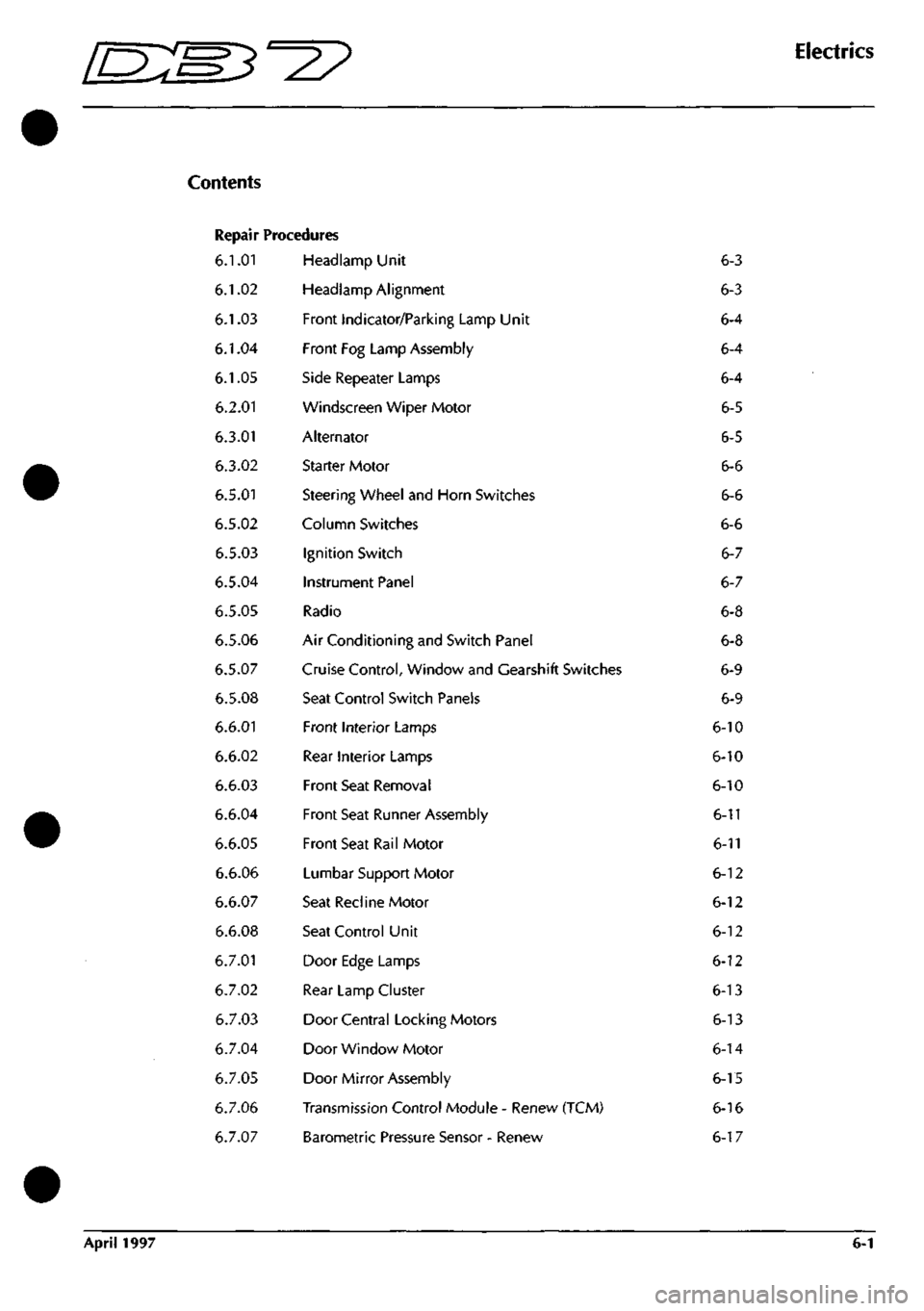
Repair Procedures
6.1.01
6.1.02
6.1.03
6.1.04
6.1.05
6.2.01
6.3.01
6.3.02
6.5.01
6.5.02
6.5.03
6.5.04
6.5.05
6.5.06
6.5.07
6.5.08
6.6.01
6.6.02
6.6.03
6.6.04
6.6.05
6.6.06
6.6.07
6.6.08
6.7.01
6.7.02
6.7.03
6.7.04
6.7.05
6.7.06
6.7.07
Headlamp Unit
Headlamp Alignment
Front Indicator/Parking Lamp Unit
Front Fog Lamp Assembly
Side Repeater Lamps
Windscreen Wiper Motor
Alternator
Starter Motor
Steering Wheel and Horn Switches
Column Switches
Ignition Switch
Instrument Panel
Radio
Air Conditioning and Switch Panel
Cruise Control, Window and Gearshift Switches
Seat Control Switch Panels
Front Interior Lamps
Rear Interior Lamps
Front Seat Removal
Front Seat Runner Assembly
Front Seat Rail Motor
Lumbar Support Motor
Seat Recline Motor
Seat Control Unit
Door Edge Lamps
Rear Lamp Cluster
Door Central Locking Motors
Door Window Motor
Door Mirror Assembly
Transmission Control Module - Renew (TCM)
Barometric Pressure Sensor - Renew
6-3
6-3
6-4
6-4
6-4
6-5
6-5
6-6
6-6
6-6
6-7
6-7
6-8
6-8
6-9
6-9
6-10
6-10
6-10
6-11
6-11
6-12
6-12
6-12
6-12
6-13
6-13
6-14
6-15
6-16
6-17
April 1997 6-1
Page 15 of 421
Em3^^^
Electrics
Ignition Switch / Instrument Panel - Removal Procedures
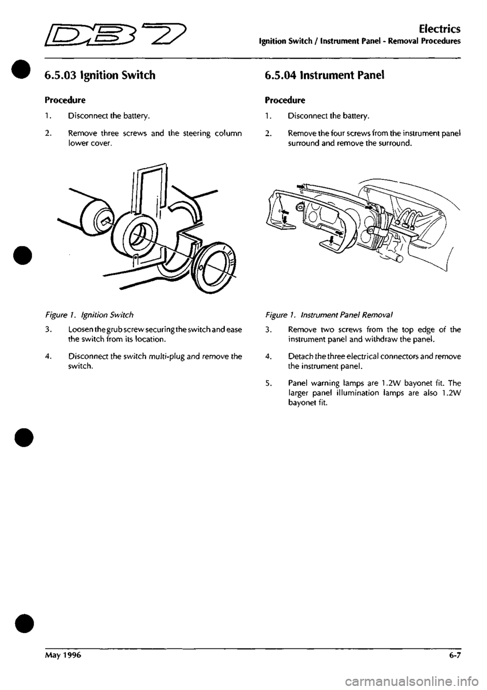
6.5.03 Ignition Switch 6.5.04 Instrument Panel
Procedure
1.
Disconnect the battery.
2.
Remove three screws and the steering column
lower cover.
Procedure
1.
Disconnect the battery.
2.
Remove the four screws from the instrument pane!
surround and remove the surround.
Figure 7. Ignition Switch
3.
4.
Loosen thegrub screw securing the switch and ease
the switch from its location.
Disconnect the switch multi-plug and remove the
switch.
Figure 1. Instrument Panel Removal
3. Remove two screws from the top edge of the
instrument panel and withdraw the panel.
4.
Detach the three electrical connectors and remove
the instrument panel.
5. Panel warning lamps are 1.2W bayonet fit. The
larger panel illumination lamps are also 1.2W
bayonet fit.
May 1996 6-7
Page 28 of 421
Electrics
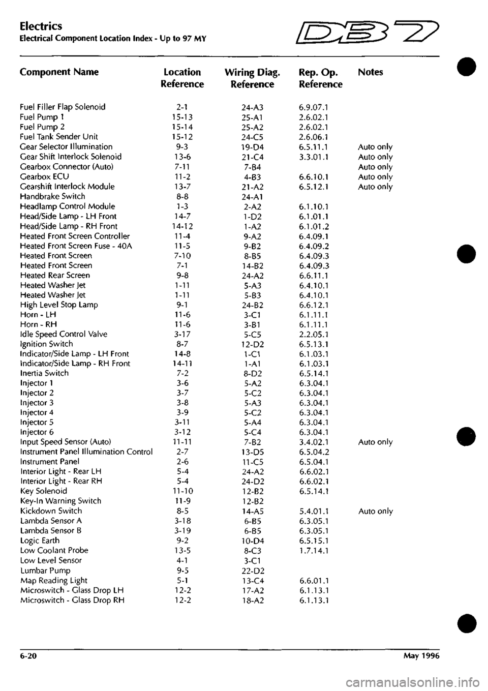
Electrical Component Location Index •
Component Name
Fuel Filler Flap Solenoid
Fuel Pump 1
Fuel Pump 2
Fuel Tank Sender Unit
Gear Selector Illumination
Gear Shift Interlock Solenoid
Gearbox Connector (Auto)
Gearbox ECU
Gearshift Interlock Module
Handbrake Switch
Headlamp Control Module
Head/Side Lamp - LH Front
Head/Side Lamp - RH Front
Heated Front Screen Controller
Heated Front Screen Fuse - 40A
Heated Front Screen
Heated Front Screen
Heated Rear Screen
Heated Washer Jet
Heated Washer Jet
High Level Stop Lamp
Horn - LH
Horn - RH
Idle Speed Control Valve
Ignition Switch
Indicator/Side Lamp - LH Front
Indicator/Side Lamp - RH Front
Inertia Switch
Injector 1
Injector 2
Injector 3
Injector 4
Injector 5
Injector 6
Input Speed Sensor (Auto)
Instrument Panel Illumination Control
Instrument Panel
Interior Light - Rear LH
Interior Light - Rear RH
Key Solenoid
Key-In Warning Switch
Kickdown Switch
Lambda Sensor A
Lambda Sensor B
Logic Earth
Low Coolant Probe
Low Level Sensor
Lumbar Pump
Map Reading Light
Microswitch - Glass Drop LH
Microswitch - Glass Drop RH
Up to 97 MY
Location
Reference
2-1
15-13
15-14
15-12
9-3
13-6
7-11
11-2
13-7
8-8
1-3
14-7
14-12
11-4
11-5
7-10
7-1
9-8
1-11
1-11
9-1
11-6
11-6
3-17
8-7
14-8
14-11
7-2
3-6
3-7
3-8
3-9
3-n
3-12
11-11
2-7
2-6
5-4
5-4
11-10
11-9
8-5
3-18
3-19
9-2
13-5
4-1
9-5
5-1
12-2
12-2
Wiring Diag.
Reference
24-A3
25-A1
25-A2
24-C5
19-D4
21-C4
7-B4
4-B3
21-A2
24-A1
2-A2
1-D2
1-A2
9-A2
9-B2
8-B5
14-B2
24-A2
5-A3
5-B3
24-B2
3-C1
3-81
5-C5
12-D2
1-C1
1-A1
8-D2
5-A2
5-C2
5-A3
5-C2
5-A4
5-C4
7-B2
13-D5
11-C5
24-A2
24-D2
12-B2
12-B2
14-A5
6-B5
6-B5
10-D4
8-C3
3-C1
22-D2
13-C4
17-A2
18-A2
Ini^'
IL-^^'^
Rep.
Op.
Reference
6.9.07.1
2.6.02.1
2.6.02.1
2.6.06.1
6.5.11.1
3.3.01.1
6.6.10.1
6.5.12.1
6.1.10.1
6.1.01.1
6.1.01.2
6.4.09.1
6.4.09.2
6.4.09.3
6.4.09.3
6.6.11.1
6.4.10.1
6.4.10.1
6.6.12.1
6.1.11.1
6.1.11.1
2.2.05.1
6.5.13.1
6.1.03.1
6.1.03.1
6.5.14.1
6.3.04.1
6.3.04.1
6.3.04.1
6.3.04.1
6.3.04.1
6.3.04.1
3.4.02.1
6.5.04.2
6.5.04.1
6.6.02.1
6.6.02.1
6.5.14.1
5.4.01.1
6.3.05.1
6.3.05.1
6.5.15.1
1.7.14.1
6.6.01.1
6.1.13.1
6.1.13.1
W3^y
Notes
Auto only
Auto only
Auto only
Auto only
Auto only
Auto only
Auto only
6-20 May 1996
Page 109 of 421
Electrics
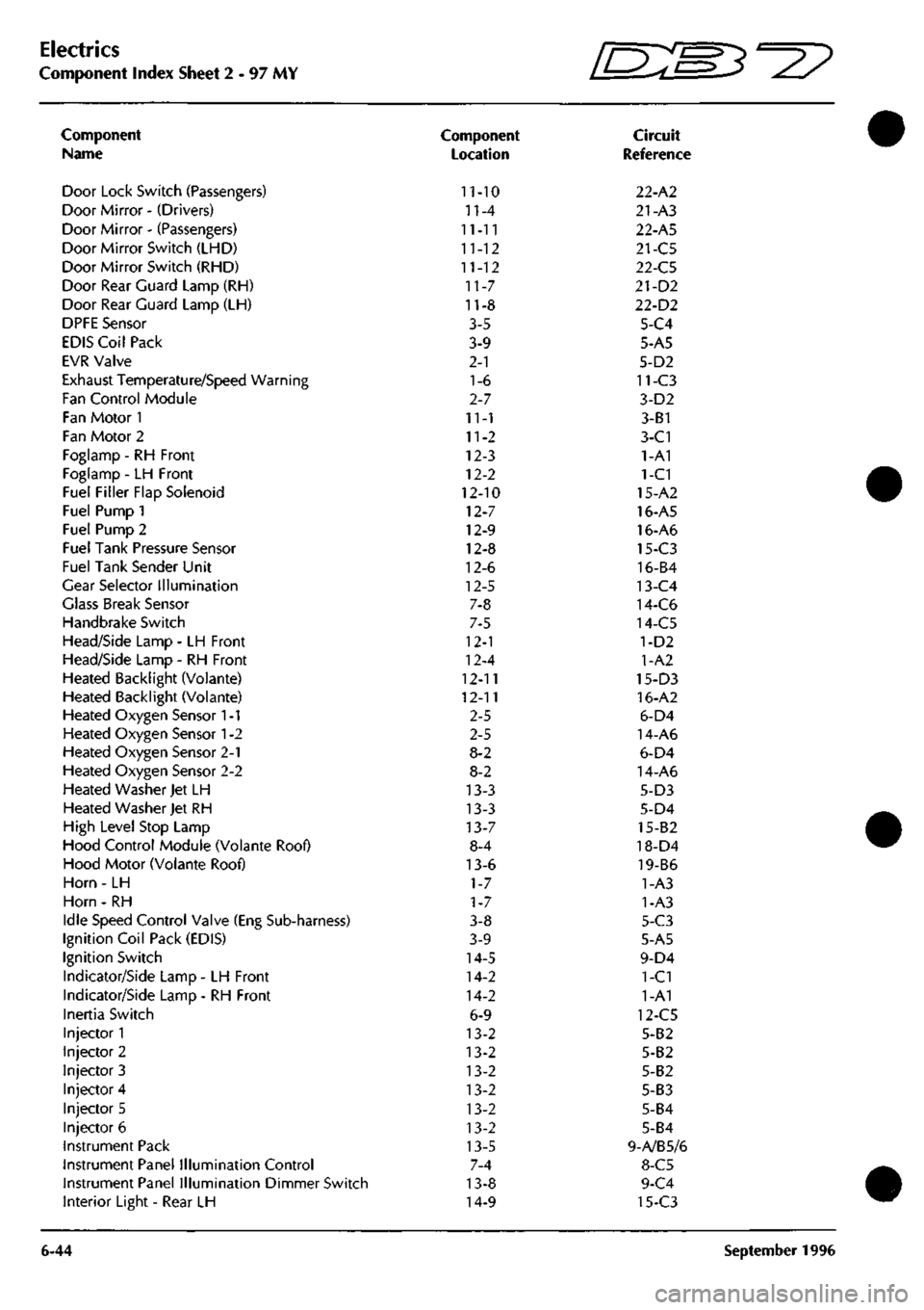
Component Index Sheet 2 - 97 MY
Component
Name
Door Lock Switch (Passengers)
Door Mirror - (Drivers)
Door Mirror - (Passengers)
Door Mirror Switch (LHD)
Door Mirror Switch (RHD)
Door Rear Guard Lamp (RH)
Door Rear Guard Lamp (LH)
DPFE Sensor
EDIS Coil Pack
EVR Valve
Exhaust Temperature/Speed Warning
Fan Control Module
Fan Motor 1
Fan Motor 2
Foglamp - RH Front
Foglamp - LH Front
Fuel Filler Flap Solenoid
Fuel Pump 1
Fuel Pump 2
Fuel Tank Pressure Sensor
Fuel Tank Sender Unit
Gear Selector Illumination
Glass Break Sensor
Handbrake Switch
Head/Side Lamp - LH Front
Head/Side Lamp - RH Front
Heated Backlight (Volante)
Heated Backlight (Voiante)
Heated Oxygen Sensor
1
-1
Heated Oxygen Sensor
1
-2
Heated Oxygen Sensor 2-1
Heated Oxygen Sensor 2-2
Heated Washer Jet LH
Heated Washer Jet RH
High Level Stop Lamp
Hood Control Module (Volante Roof)
Hood Motor (Volante Roof)
Horn - LH
Horn - RH
Idle Speed Control Valve (Eng Sub-harness)
Ignition Coil Pack (EDIS)
Ignition Switch
Indicator/Side Lamp - LH Front
Indicator/Side Lamp - RH Front
Inertia Switch
Injector 1
Injector 2
Injector 3
Injector 4
Injector 5
Injector 6
Instrument Pack
Instrument Panel Illumination Control
Instrument Panel Illumination Dimmer Switch
Interior Light - Rear LH
6-44
Component
Location
11-10
n-4
11-11
11-12
11-12
11-7
11-8
3-5
3-9
2-1
1-6
2-7
11-1
11-2
12-3
12-2
12-10
12-7
12-9
12-8
12-6
12-5
7-8
7-5
12-1
12-4
12-11
12-11
2-5
2-5
8-2
8-2
13-3
13-3
13-7
8-4
13-6
1-7
1-7
3-8
3-9
14-5
14-2
14-2
6-9
13-2
13-2
13-2
13-2
13-2
13-2
13-5
7-4
13-8
14-9
fEB^-^?
Circuit
Reference
22-A2
21-A3
22-A5
21-C5
22-C5
21-D2
22-D2
5-C4
5-A5
5-D2
11-C3
3-D2
3-B1
3-C1
1-A1
1-C1
15-A2
16-A5
16-A6
15-C3
16-B4
13-C4
14-C6
14-C5
1-D2
1-A2
15-D3
16-A2
6-D4
14-A6
6-D4
14-A6
5-D3
5-D4
15-82
18-D4
19-B6
1-A3
1-A3
5-C3
5-A5
9-D4
1-C1
1-A1
12-C5
5-B2
5-B2
5-B2
5-B3
5-B4
5-B4
9-A/B5/6
8-C5
9-C4
15-C3
September 1996
Page 224 of 421
Electrics
Seat Belt Pretensioner ^?
060C Warning Lamp Short Circuit
060C will be logged if the nnonitor current flow
through the SRS/Airbag warning lamp is excessive.
The warning lamp circuit is normally at 12 volts and
is switched to ground by the airbag control module
or by the pretensioner control module when one of
these control modules detects a fault.
If either control module connector is displaced and
the ignition is switched on, the warning lamp will
be illuminated via the ground shorting link between
pins!
and 2 ofthe pretensioner controller connector
or pins 4 and 5 of the airbag controller connector,
both control modules must be checked for the
appropriate DTC to isolate which circuit is at fault.
Procedure
1.
Connect the PDU to the lower diagnostic socket
and access the pretensioner control module. Verify
that an 060C code is logged and note if the fault is
shown as intermittent. Note any other codes in the
DTC log and then clear all codes. Go to step 2.
If fault code 060C is not logged, go to the diagnostics
section of the airbag system.
2.
Check the security of the pretensioner control
module connector.
If the connector is secure, go to step 3.
If the connector isdisplaced,resecu re theconnector.
Clear all logged DTCs and retest the vehicle to
ensure that the problem is resolved.
3. Access the SRS/Airbag warning lamp and check the
lamp resistance.
If the resistance is approximately
120£2,
the lamp is
good.
Refit the lamp and go to step 4.
If the resistance of the lamp is significantly less than
approximately 120^, fit a new lamp and refit the
instrument panel. Clear the logged DTCs from the
pretensioner control module and retest the vehicle
to ensure that the problem is resolved.
4.
If the checks in step 3 are good, the low circuit
resistance must be in the instrument pack or in the
control module. Replace the pretensioner control
module and reconnect all components.
6. Switch on the ignition and then test the vehicle.
If the 060C code is logged again, replace the
instrument pack.
060D Warning lamp open circuit
060D will be logged if the monitor current flow
through the SRS/Airbag warning lamp is below the
normal monitor level.
The warning lampcircuit is normally at 12 voltsand
is switched to ground by the airbag control module
or by the pretensioner control module when one of
these control modules detects a fault.
Procedure
Connect the PDU to the lower diagnostic socket
and access the pretensioner control module. Verify
that an 060D code is logged and note if the fault is
shown as intermittent. Note any other codes in the
DTC log and then clear all codes. Go to step 2.
lffaultcode060D is not
logged,
gotothediagnostics
section of the airbag system.
Switch off the ignition. Access the SRS/Airbag
warning lamp and check the lamp resistance. The
resistance should be approximately 120Q.
If the resistance is 120i2, go to step 3.
If the lamp resistance is significantly lower than
120^2,
replace the lamp. Retest the vehicle to
ensure that the problem is resolved.
Wait 10 minutes after switching off the ignition to
ensure that the pretensioner firing capacitors have
fully discharged.
Disconnect the pretensioner control module and
temporarily cheat the warning lamp shorting link.
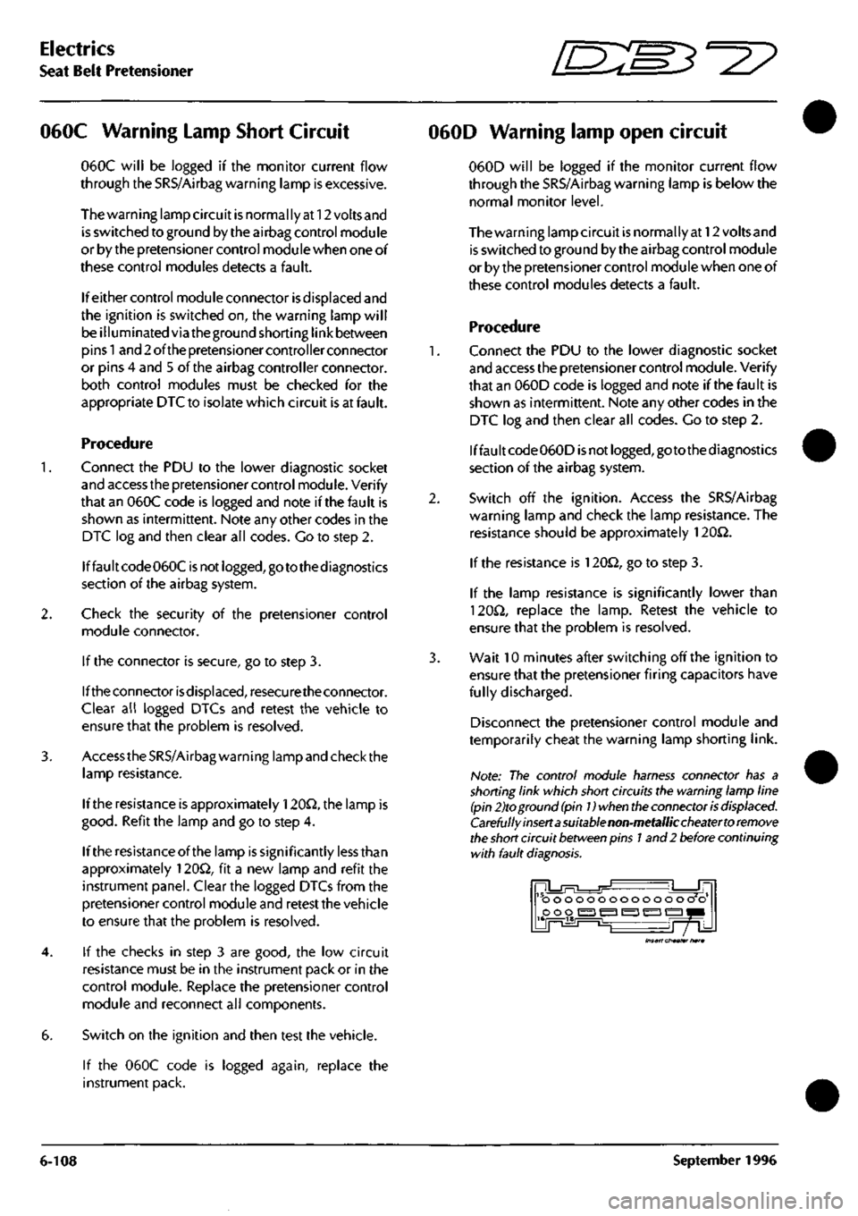
Note: The control module harness connector has a
shorting link which short circuits the warning lamp line
(pin 2)to ground
(pin
Dwhen
the
connector
is
displaced.
Carefully insert a suitable non-metallic cheater to remove
the
short
circuit
between
pins
1
and 2 before continuing
with fault
diagnosis.
ooooooooooooo o o poo
i^i
^ ^ ^ 1^1
Insert cheater hare
6-108
September
1996
Page 229 of 421
O" D^?
Body and Trim
Contents
Contents
Body and Trim
Body Repair
Potential Risks
Precautions
General Repair Notes
Steel Body Parts - Repair, Remove and Replace
RTM Body Parts
Body Panel and Trim Removal
Front Apron
Front Undertray
Wheel Arch Liners
Side Sills (top fixings)
Side Sills (bottom fixings)
Rear Bumper
Doors
Door Liners
Door Liner (components)
Steering Wheel
Column Switches
Instrument Panel (surround)
Instrument Panel
Facia Underscuttles
Glove Box
Facia Mountings (1)
Facia Mountings (2)
Console Instruments
Radio
Front Seats
Ashtray
Centre Console
Seat ECU Covers
Rear Console
Rear Seats and C Post Trim
Quarter Panels, B Post Panels, Parcel Shelf
Headlining
Roof System Description and Repair Procedures
Vol ante Roof
Roof and Rear Quarter Light Control
Roof Component Location
Roof Control System
9.0.02.1
Roof Removal/Replacement
9.0.02.3
Roof Hydrailic Control System
9.0.02.5
Bleeding the Roof Hydraulic System
9.1.01.1
Rear Quarter Window Renewal
9.1.01.2
Rear Quarter Glass Adjustment
9.1.01.4
Rear Quarter Window Lift Motor - LH
9.1.01.5
Rear Quarter Window Lift Motor - RH
Roof Sealing and Wind Noise
9.2.01.5
'A' Post/Header Sealing and Lock Adj
9.2.01.6
Roof Seals - Adjustment
9.2.01.7
Cheater Plate Seals - Adjust/Renew
9.2.01.8
Door Glass Adjustment
Alcantara Cleaning
7-1
7-2
7-2
7-3
7-3
7-4
7-5
7-6
Sheet 1
Sheet 2
Sheet 3
Sheet 4
Sheet 5
Sheet 6
Sheet 7
Sheet 8
Sheet 9
Sheet 10
Sheet 11
Sheet 12
Sheet 13
Sheet 14
Sheet 15
Sheet 16
Sheet 17
Sheet 18
Sheet 19
Sheet 20
Sheet 21
Sheet 22
Sheet 23
Sheet 24
Sheet 25
Sheet 26
Sheet 27
7-7
7-7
7-8
7-9
7-10
7-11
7-12
7-13
7-14
7-15
7-16
7-17
7-17
7-18
7-19
7-20
7-21
May 1996 7-1
Page 234 of 421
Body and Trim
Body Panel and Trim Removal 5^7
Body Panel and Trim Removal
The following diagrams show the fixings for all
removeable body and trim panels.
Sheet 1. Front Apron
Sheet 2. Front Undertray
Sheet 3. Wheel Arch Liners
Sheet 4. Side Sills (top fixings)
Sheets. Side Sills (bottom fixings)
Sheet 6. Rear Bumper
Sheet 7. Doors
Sheet 8. Door Liners
Sheet 9. Door Liner (components)
Sheet 10. Steering Wheel
Sheet 11. Column Switches
Sheet 12. Instrument Panel (surround)
Sheet 13. Instrument Panel
Sheet 14. Facia Underscuttles
Sheet 15. Glove Box
Sheet 16. Facia Mountings (1)
Sheet
1
7. Facia Mountings (2)
Sheet 18. Console Instruments
Sheet 19. Radio
Sheet 20. Front Seats
Sheet
21.
Ashtray
Sheet 22. Centre Console
Sheet 23. Seat ECU Covers
Sheet 24. Rear Console
Sheet 25. Rear Seats and C Post Trim
Sheet 26. Quarter Panels, B Post Panels, Parcel Shelf
Sheet 27. Headlining
7-6 May 1996
Page 246 of 421
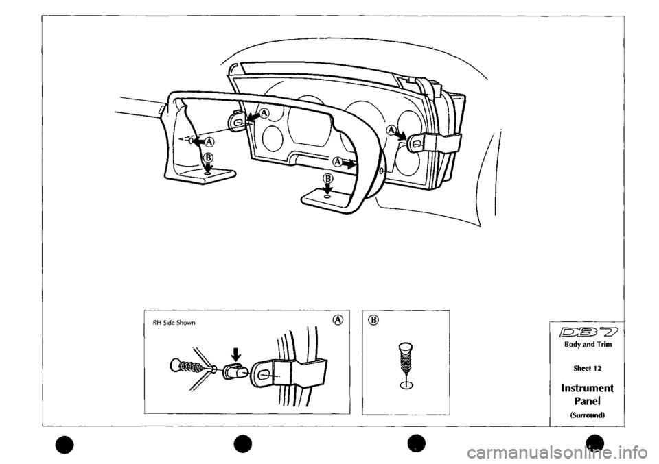
Body
and
Trim
Sheet
12
Instrument
Panel
(Surround)
Page 332 of 421
^2?
Air Conditioning Repair Procedures
Hose - Compressor to Evaporator/Air-Con Unit Renew
8.1.06.1 Hose-Compressor
to
Evaporator
Renewal
Procedure
1.
Open the bonnet and fit a wing cover.
2.
Depressurise the air conditioning systenn.
3. Remove the hose to evaporator valve clamping
plate,
disconnect the hose from the valve, remove
and discard the 'O' ring
seal.
4.
Fit a blanking plug to the evaporator valve. Release
the evaporator hose securing clips.
5. Remove the compressor outlet port retaining bolt.
6. Disconnect the hose from the compressor, discard
the hose complete with 'O' ring seals.
7. Connect the hose to the evaporator valve and
tighten clamp onto the hose.
8. Route the hose to the compressor, fit a new 'O' ring
seal and connect it to the compressor.
9. Position the outlet port retaining plate on the
compressor, fit and tighten the securing bolt.
10.
Refit the hose to the clips.
11.
Charge the air conditioning system.
12.
Remove the wing cover and close the bonnet.
8.2.01.1 Air Conditioning Unit Renewal
1.
Disconnect the battery earth
lead.
2.
Drain the engine coolant into a suitable container.
3. Depressurise the air conditioning system.
4.
Disconnect the high and low pressure hoses and
expansion valve from the air conditioning unit (see
expansion valve renewal).
5. Slacken the coolant hose to the heater matrix pipe
securing clips and disconnect the hoses from the
matrix. (This will require the removal of the air
intake hose for access.)
6. Remove the following items from inside the car:
front seats
underscuttle panels/knee bolsters
glove box assembly
facia trim (walnut trim)
radio and ashtray
centre console switch panel assembly
instrument panel and surround trim
steering wheel and column
facia assembly complete
hoses - distribution box to door vents
facia support frame
Details and drawings of the above operations can
be found in the electrical and trim sections.
Disconnect the vacuum hoses from the blower
motors, water valve and reservoir.
Un-clip the electrical harness from the air
conditioningunit, release theelectrical connections
and reposition the harness to allow removal of the
unit.
Displace and remove the footwell ventilator ducts
and hoses (Fig. 1-1).
May 1996 8-55
Page 336 of 421
'nzm^=2?
Air Conditioning Repair Procedures
Blower Motor Renewal
8.2.07.1 Ambient Temperature Sensor
Renew
?\gure
1.
The ambient temperature sensor is located in the
left hand side of the air plenum chamber under the
lower windshield panel (Fig. 1-1).
Procedure
1.
Disconnect the battery earth
lead.
2.
(On left hand cars) Remove the steering wheel
(mark the position on the column shaft for re
assembly), instrument pack and surround
trim.
2.
(On right hand cars) Removethegloveboxlidand
liner.
3. Disconnect the hose from the distribution box to
the side vent outlet. Reposition the hose for access.
4.
Disconnect the sensor block connector.
The sensor has locating clips and is a push fit into
the plenum chamber.
5. Lever the sensor free.
8.2.08.1 Blower Motor Driver Side
Renewal
8.2.09.1 Blower Motor Passenger Side
Renewal
1.
Move seat
fu 1
ly rearward.
2.
Disconnect vehicle battery ground
lead.
3. Remove the under scuttle/knee pad bolster.
4.
Remove the lower brace bar/facia assembly
underscuttle knee pad.
Driver Side Only
5. Removetheinstrumentpack, bonnetreieasehandle
mounting bracket and steering column..
6. Disconnect the air hose from the facia side air
outlet.
Passenger Side Only
7. Remove the glove box lid and liner.
Both
8. Remove the nuts securing the component panel
(Fig.
1-1).
Figure 1.
9. Ease the component panel clear for access to the
blower assembly mounting bolts.
10.
Disconnect the pliable trunking from the stub pipes
on either side of the air conditioning unit
(Fig.
1
-3).
11.
Disconnect the blower motor electrical harness at
the block connector.
May 1996 8-59