wiring diagram ASTON MARTIN DB7 1997 Workshop Manual
[x] Cancel search | Manufacturer: ASTON MARTIN, Model Year: 1997, Model line: DB7, Model: ASTON MARTIN DB7 1997Pages: 421, PDF Size: 9.31 MB
Page 10 of 421
Electrics
Electrical Component Location and Wiring Information - Up to 97 MY
Component Index 6-19
Component Location Diagrams 6-23
Electronic Control Unit Location Diagram 6-38
Relay Panel, Fusebox and Earth Point Location Diagram 6-39
Loom Location Diagrams 6-40
Wiring Diagrams and Splice Lists 6-42
Electrical Component Location and Wiring Information - 97 MY
Component Index 6-43
Component Location Diagrams 6-47
Relay Location Diagrams 6-64
Wiring Diagrams and Splice Lists 6-68
Airbag System - Repair and Diagnostic Procedures 6-69
Seat Belt Pretensioner System - Repair and Diagnostic Procedures 6-101
Security System (Restricted Circulation) 6-111
PATS System (Restricted Circulation) 6-121
97.5 Model Year
6.6.03 Seat Removal (97.5 MY)
6.6.08 Seat Control Module (97.5 MY)
6-127
6-128
6-2 April! 997
Page 26 of 421
Electrics
Electrical Component Location and Wiring Information in::m3^?
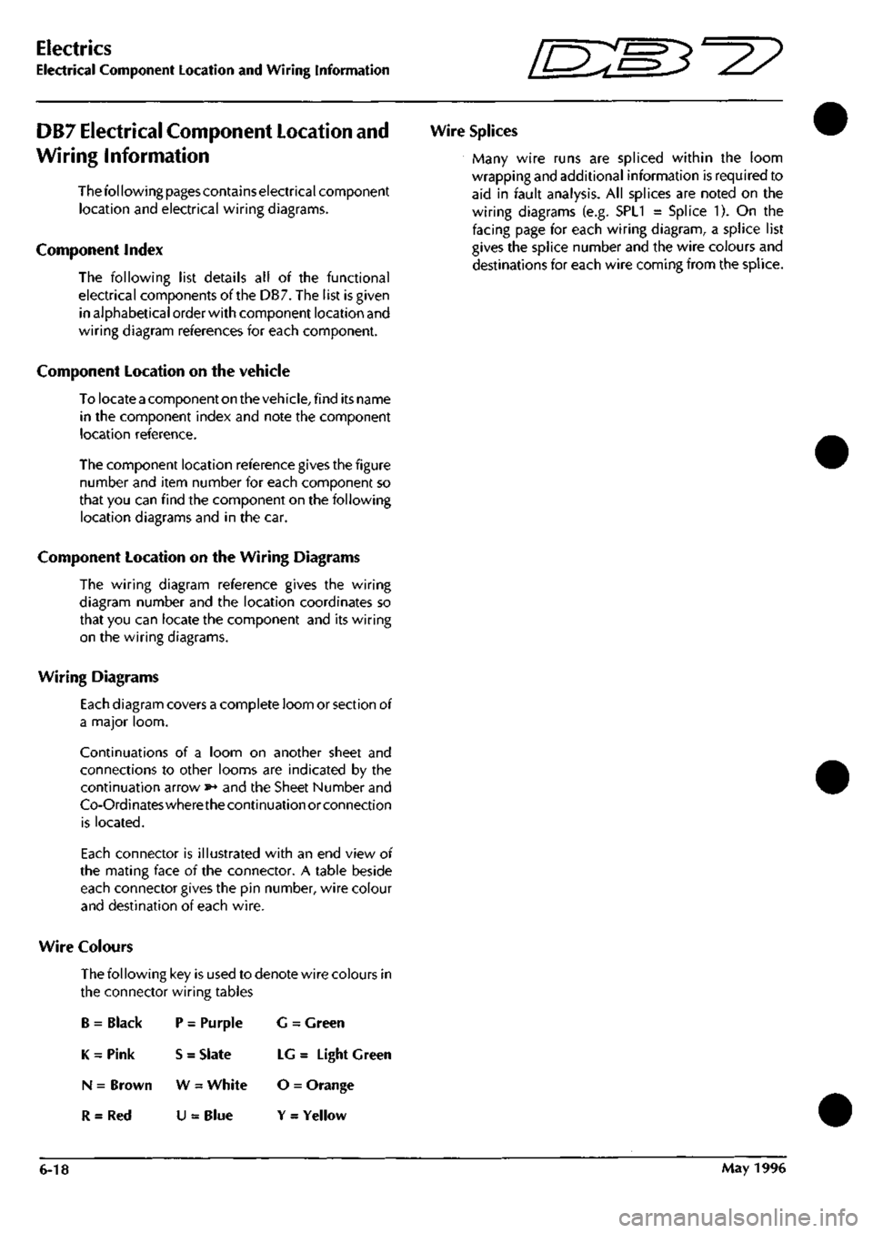
DB7 Electrical Component Location and
Wiring Information
Thefol lowing pages contains electrical component
location and electrical wiring diagrams.
Component Index
The following list details all of the functional
electrical components of the DB7. The list is given
in alphabetical order with component location and
wiring diagram references for each component.
Component Location on the vehicle
To locate a component on the veh
icie,
find its name
in the component index and note the component
location reference.
The component location reference gives the figure
number and item number for each component so
that you can find the component on the following
location diagrams and in the car.
Component Location on the Wiring Diagrams
The wiring diagram reference gives the wiring
diagram number and the location coordinates so
that you can locate the component and its wiring
on the wiring diagrams.
Wiring Diagrams
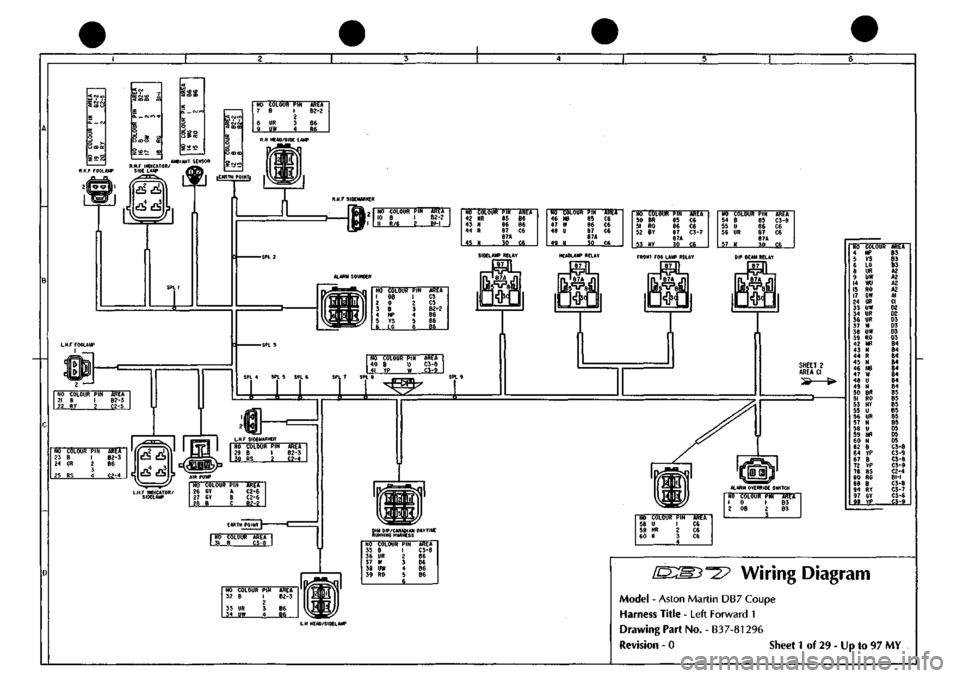
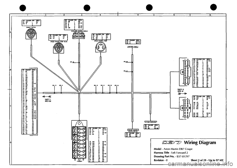
Each diagram covers a complete loom or section of
a major loom.
Continuations of a loom on another sheet and
connections to other looms are indicated by the
continuation arrow »* and the Sheet Number and
Co-Ordinateswherethecontinuation or connection
is located.
Each connector is illustrated with an end view of
the mating face of the connector. A table beside
each connector gives the pin number, wire colour
and destination of each wire.
Wire Colours
The following key is used to denote wire colours in
the connector wiring tables
B = Black P = Purple G = Green
K = Pink S = Slate LG = Light Green
N = Brown W = White O = Orange
R = Red U = Blue Y = Yellow
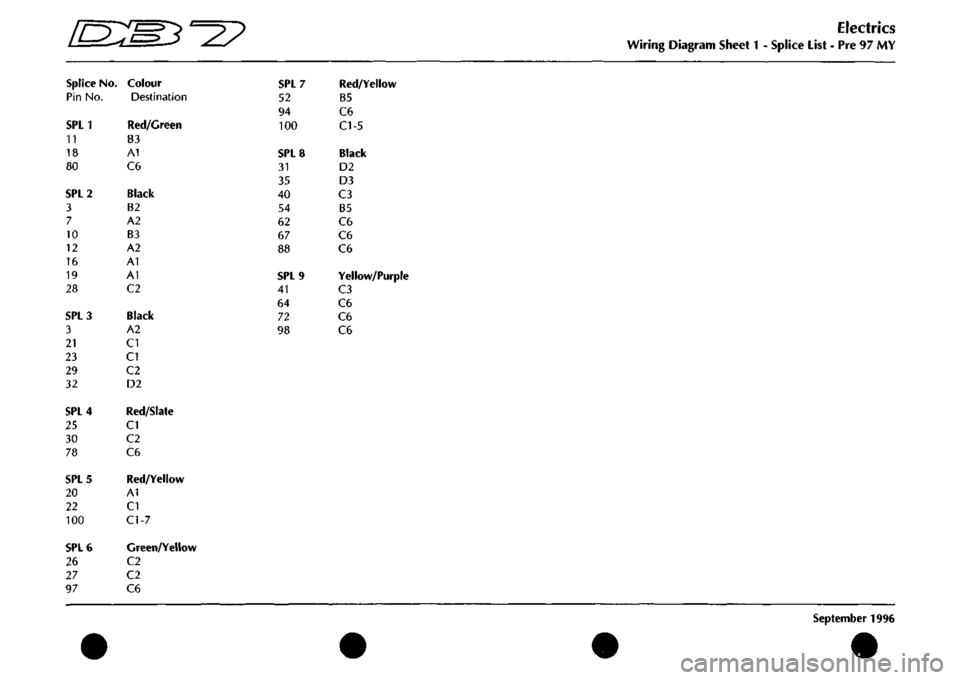
Wire Splices
Many wire runs are spliced within the loom
wrapping and additional information is required to
aid in fault analysis. All splices are noted on the
wiring diagrams (e.g. SPL1 = Splice 1). On the
facing page for each wiring diagram, a splice list
gives the splice number and the wire colours and
destinations for each wire coming from the splice.
6-18 May 1996
Page 50 of 421
Electrics
Wiring Diagram Sheet
1 -
Splice List
- Pre 97 MY
September
1996
[DSlMJ-^y^
Splice
No.
Pin No.
SPLl
11
18
80
SPL2
3
7
10
12
16
19
28
SPL3
3
21
23
29
32
SPL4
25
30
78
SPL5
20
22
100
SPL6
26
27
97
Colour
Destination
Red/Green
B3
A1
C6
Black
B2
A2
B3
A2
A1
A1
C2
Black
A2
CI
CI
C2
D2
Red/Slate
CI
C2
C6
Red/Yellow
A1
CI
C1-7
Green/Yellow
C2
C2
C6
SPL7
52
94
100
SPL8
31
35
40
54
62
67
88
SPL9
41
64
72
98
Red/Yellow
B5
C6
CI-5
Black
D2
D3
C3
B5
C6
C6
C6
Yellow/Purple
C3
C6
C6
C6
Page 51 of 421
NO COLOUR
PIN
7
B 1 2
8
UR 3
9
UW 4
AREA B2-2
66 Be
NO
COLOUR
PIN
AREA
10 8 I 82-2 11 R/6 2 Bl-i
NO COLOUR
PIN
42
NR 65
4}
N 86
44
R 87 87A
45
N 30
AREA
86 86 C6
C6
NO COLOUR
PIN
46
NB 85
47
W 86
48
U 87 87A
49
N 30
ARtA
C6 C6 ce C6
•M SO 51 52
53
COLOUR
PIN
BR
85
RO
86
BY
87
87A N»
30
mk C6 C6
C3-7
C6
NO COLOUR
PIN
54
8 85
55
U 86
56
UR 87 e7A
57
N 30
AREA C5-8
C6 C6
C6
SIDCLAHP BCLAY
I
87
I
HUCUaP RELAY
NO 1 2 3 4 5 6
COLOUB
08 0 8 NP YS LG
PIN 1 2 3 4 5 6
AREA
C5 C5 82-2 86 86 86
NO COLOUR PIN 40 B U
41
YP w
AREA C3-8 C3-9
NO
COLOUR
PIN
ARET
23 8 I 82-3
24
CR 2 86
5
25
RS 4 C2-4 %^
NO COLOUR
PIN
26
GY A
27
GY B
28
B C
AREA C2-6 C2-6
82-2
IH POIHT |-
nro
COLOUR AREA
I
31 B C3-8
NO
COLOUR
PIN
AREA
32 B I 82-3 2 33 UR 3 86
34
UW 4 86
fRONT
FOG
LAUP RELAY DIP BEAU RELAY
SHEET
2
AREA
CI
ALARM OVERRIDE SWITCM
up)
L.H
HEA0/5IDCLA1«>
NO COLOUB 35
B
36
UR
37
W
38
UW
39
RO
PIN 1 ? 3 4
5 6
AREA C3-8
B6 66 B6 86
NO COLOUR
PIN
58
U 1
59
NR 2
60
N 3 4
AREA
C6 C6 C6
NO COLOUR
PIU
1
0 1
2
08 2 5
AlttA
B3 83
NO COLOUR 4 NP 5 YS 6 LG e UR 9 UW 14 WU 15 RO 17 GW 24 GR 33 UW 34 UR 36 UR 37 W 38 UW 39 RO 42 HR 43 N 44 R 45 N 46 N8 47 W 48 U 49 N 50 BR 51 RO 53 NY 55 U 56 UR 57 N 58 U 59 NR 60 N 62 8 64 YP 67 8 72 YP 78 RS 80 RG 88 B 94 RY 97 GY 98 YP
mi 63 83 B3 A2 A2 A2 A2 Al CI 02 D2 D3 03 03 03 84 84 64 84 84 84 84 84 85 85 85 65 85 85 05 05 05 C3-8 C3-9 C3-8 C5-9 C2-4 Bl-I C3-8 C3-7 C3-6 C3-9
1^:^^-^?
Wiring Diagram
Model - Aston Martin DB7 Coupe
Harness Title - Left Forward 1
Drawing Part No. - B37-81296
Revision - 0 Sheet
1
of 29 - Up to 97 MY
Page 52 of 421
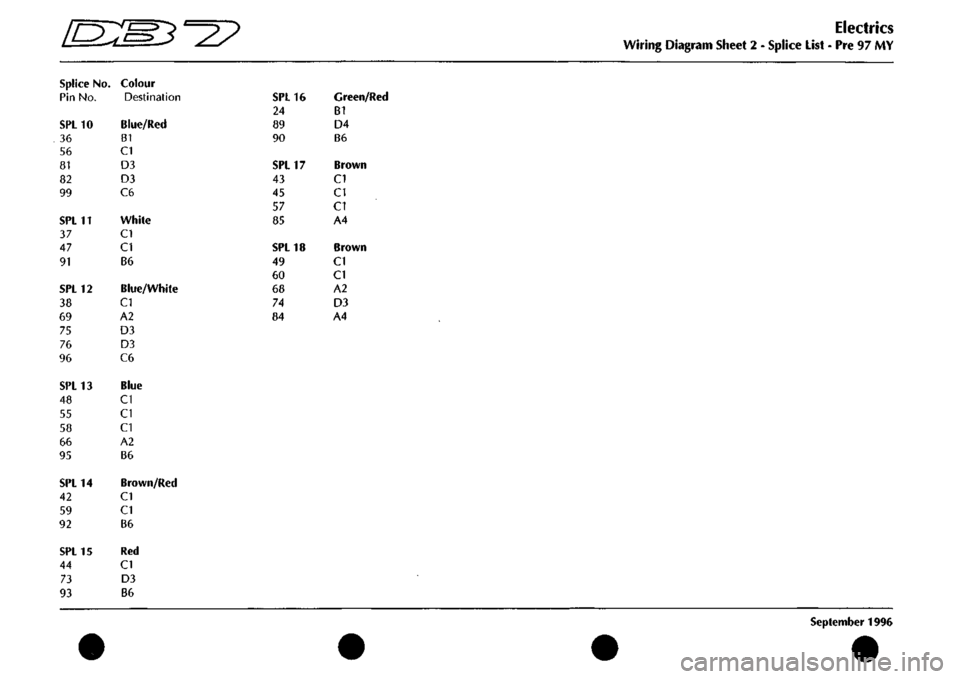
^^?
Splice
No.
Pin No.
SPL10
36
56
81
82
99
SPL11
37
47
91
SPL12
38
69
75
76
96
SPL13
48
55
58
66
95
SPL14
42
59
92
SPL15
44
73
93
Colour
Destination
Blue/Red
B1
CI
D3
D3
C6
White
CI
CI
B6
Blue/White
CI
A2
D3
D3
C6
Blue
CI
CI
CI
A2
B6
Brown/Red
CI
CI
B6
Red
CI
D3
86
SPL16
24
89
90
SPL17
43
45
57
85
SPL18
49
60
68
7^
84
Green/Red
B1
D4
B6
Brown
CI
CI
CI
A4
Brown
CI
CI
A2
D3
A4
Electrics
Wiring Diagram Sheet
2 -
Splice List
- Pre 97 MY
September
1996
Page 53 of 421
Nb 61 62
COLOUR
PIN
BR
1
B
2
}
kKk
B6 CI
BONNET SWITCH
80
RC
es
B
S4
RY 97 Sr
98
YP
NO COLOUH 65
UB
66
U
67
B
68
N
69
UW
t>IN
1 ? 3 4
5
i
-
AREA B6 B3-I3 CI B4-i8 B2-I2
HEADLAMP CONTROL MODULE
NO COLOUR
PIN
63
YO 1
64
YP 2
?
Uiti
C6 CI
NO 70 71
?2
COLOUR
PIN YW YB
YP_.
1 2 3
AREA
C6 C6
V.
.,
SPEED CONTROL
W»
VALVE SPEED CONTROL
PUW
84 N 84-18 85 H eiJi
I BATTERY POST
|
SPL
15
SPL
16
I
i 1 I
rUSEBOX
NO
COLOW
73
R
39
RO
74
N
53
NY
75
UW
34
UW
76
UW
9
UW
77
RS
78
RS
79
RG
80
RC
81
UR
33
UR
82
UR
8
UR
83
WK
6
LG
PIN 1 2 J
4 6 6 7 8
9 10 II 12 13 14 15 16
1/
IS 19 20 21
li
AREA
B3-15
CI
B4-I8
CI
B2-I2
Bl
B2-I2
Bl B6 Dl B6 Dl
B2-I0
61
B2-I0
Bl Be Bl
1 II
^0
D
("
c
D
Q
00=^ Q
D
0
Q
Q
0
Q
Q
QOZ
Q
0
G
G
NO COLOUF 90 GR 14 WU 17 GW 77 RS 83 DM 91 W 92 NR 93 R 61 BR 94 RY 95 U 79 RG 65 UB 87 YR 46 NB 86 BK 4 NP 5 YS
PIN 1 ? 3 4 5 6 7 8 9 10 II 12 13 14 15 16 17
,1?,
,
AREA B4-I6 Bl Bl 03 03 B2-II 83-14 83-15 Al 01 83-13 D3 A2 04 CI 04 Bl Bl
SHEET
8
AREA
Al
.S
^
(•
QQl 0
Gl,
0
G
Qcm
G
0
G
0
G
0
NO COLOUR 96
UW
97
CY
98
YP
70
YW
71
YB
51
RO
15
RO
99
UR
63
YO
50
BR
P»i 1
2 3
4 5 6 7
8 9 10
II 12 1?
AREA 82-12
Dl
01 A3 A3 CI 81
82-10
A2 CI
'LH SIDE REPEATER'
fcRUISE
CONTROL!
CLUTCH
SWITCH
NO COLOUR AREA 88
B Dl
99
{R
E±J1
NO COLOUR AREA 86 BK 86 67 YR B6
^27 Wiring Diagram
Model
-
Aston Martin
DB7
Coupe
Harness Title
-
Left Forward
2
Drawing Part No.
-
B37-81297
Revision
- 0
Sheet
2 of 29
-
Up to 97 MY
Page 54 of 421
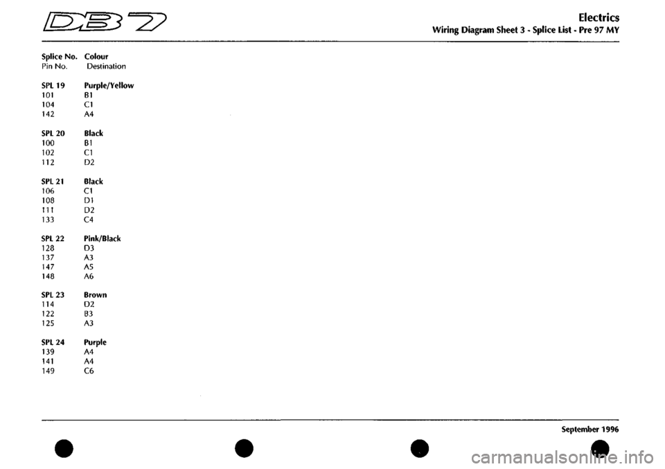
'^^
Splice
No.
Pin
No.
SPL19
101
104
142
SPL20
100
102
112
SPL21
106
108
111
133
SPL22
128
137
147
148
SPL23
114
122
125
SPL24
139
141
149
Colour
Destination
Purple/Yellow
B1
CI
A4
Black
B1
CI
D2
Black
CI
DI
D2
C4
Pink/Black
D3
A3
A5
A6
Brown
D2
B3
A3
Purple
A4
A4
C6
Electrics
Wiring Diagram Sheet 3 - Splice List - Pre 97 MY
September 1996
Page 55 of 421
NO COLOUR
PIN
116
NV I
I?
B ?
AREA A6
Si.
H6
COLOUR
fiN
ABEX"
125
N I
B3-23 12?
BY 2 SS_
NO
COLOUR
PIN
100
B I
101
PY ?
AREA B2-20 BI-19
HO
COLOUR
117
B
119
B
120
B
AREA
A2 A2
_«
NO COLOUR
PIN
ASET
103
B I CI
105
Py ' CI
NO COLOUR
PIN
102
B 1
103
B 1
lOfl
PT 2
105
PY 2
Ali^A B2-20
Bl
BI-19
fl
EARTH POINT
COOLANT
LOW
LEVEL SENSOR
AIR
CON
RELAY
l«
SPl
19
SPL
20
HO COLOUR
PIN
135
NS 65
136
UB 86
137
KB 87
87A
138
RH 3?
AREA
C6 C6
C3-22
..»,
.
NO COLOUR
PIH
133
P 85
140
PB 86
141
P 87
87A
14?
PY 30
AREA C4-24 ce C4-24
.BLI9..
NO COLOUR
PIH
115
N 85
143
BC 86
144
WY 87
S7A 110
WR 30
AREA 02 B4 C6
C2
NO COLOUR
PIK
146
RY 85
120
8 86
147 KB
87
129
UR 87A
130 BG
30
ARCA
A6 B2 C3-22 03 03 STARTER SOLENOID RELAY FAN
RUN ON
RELAY
NO COLOUR AREA 121
WR £5_
HO COLOUR 124
NG
146
RY
126
BY
116
NY
PIN 85 86 8/ 87A
55
AREA
A2 A5 A2
A2
NO COLOUR
PIH
123
NY 85
127
UN 86
148
KB 87
87A
lie
HY 30
AREA
B2 D3
C3-22
.^2...
l/
NO COLOUR
PIN
106
B I
W-S&
2_
AREA 82-21 C6 LOW LEVEL SENSOR
NO COLOUR PIN
ARET
I 110
WR 2 «4
STARTER MOTOR SOLENOID
NO COLOUR III
B
112
e
AREA B2-2I 82-20
SCREEN WASH PUMP
NO COLOUR
PIN
lOe
B 1
109
LCB 2
3 4
AR^A B2-2I C6 NO 113 114 l|^
COLOUR N N H
AlttA A2 B3-23
M
BATTERY
POSTL
NO COLOUR
133
B
134
aw
AREA B2-2I
J
RH
SIDE n REPEATER
NO COLOUR
PIN
131
YR I
132
BK 2
AREA ce C6 J CRUISE CONTROL ^ CLUTCH SWITCH
c
D:
r
ID ID
i D)
IDczt
mm
ffl
m
m m
ID Ul
ii=ir
i m
m ID
Trff'TsrawPir
134
OW
144
WY
135
NS
136
UB
138
RN
140
PB
IJI
YR
132
BK
121
WR
145
BC
109
LCB
149
P
107
BS
1 2 3 4 5 6 7 8 9
10
II 12 13 14 15 16 17 18 19
_.29
AREA
C4 A4 A3 A3 A5 A4 C4 C4 62 B4
01
C4-24
CI
NO COLOUR
PIN
127
UN 1
128
KB 2
129
UR 3
130
Bf. 4
AREA
AS
C3-22
A5
«5
SHEET
14
AREA
B4
SHEET
6
AREA
B3
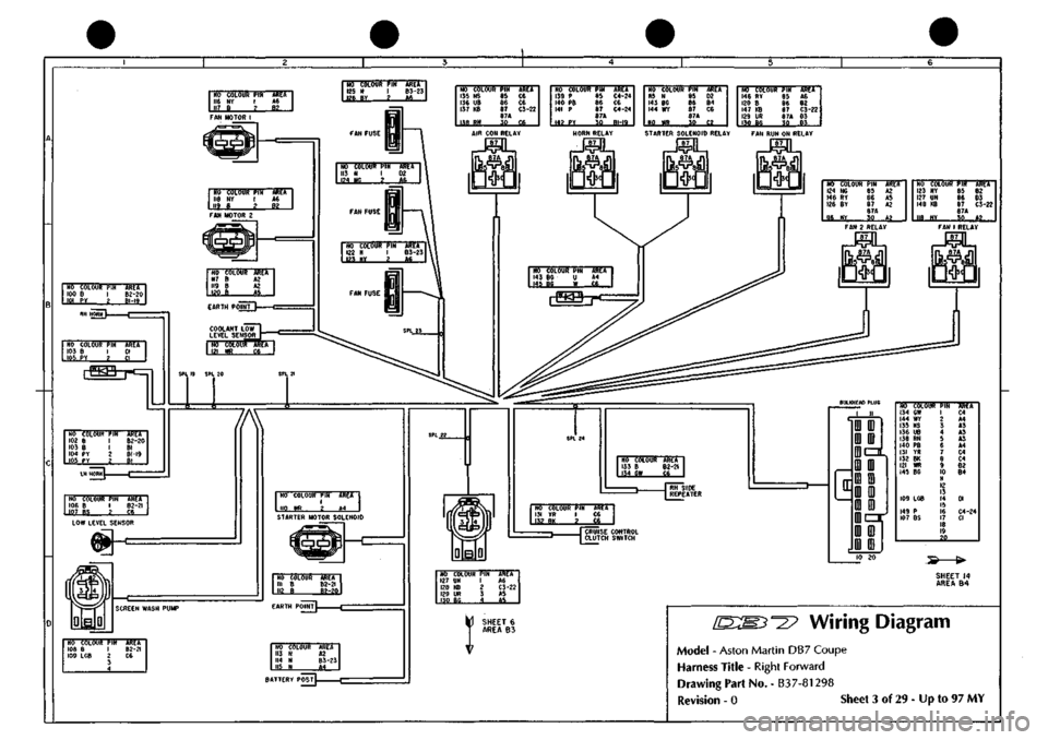
^27
Wiring Diagram
Model
-
Aston Martin DB7 Coupe
Harness
Title
-
Right Forward
Drawing
Part No.
-
B37-81298
Revision
- 0
Siieet
3 of
29
-
Up
to 97 MY
Page 56 of 421
^?
Splice
No.
Pin No.
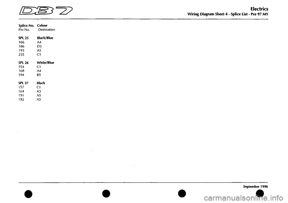
SPL25
166
186
193
235
SPL26
154
168
194
SPL27
157
164
191
192
Colour
Destination
Black/Blue
A4
D3
A5
CI
White/Blue
CI
A4
B5
Black
CI
A3
A5
A5
Electrics
Wiring Diagram Sheet
4 -
Splice List
- Pre ^1 MY
September
1996
Page 57 of 421
NO COLOUR
159 K 160 0
PIN 1 2 3 4 5 6 7 S 9 10 M 12 13 14
AREA
B6 06
SERIAL COMMS CONNECTOR NO COLOUR 161 RP 162 RG 163 BK 164 B I6S RK
PIN 1 ? 5 4 5 6
AREA B9 B5 Dl B4-27 Dl
NO COLOUR PIN 166 BU 1 16? GP 2
les
wu
3
im B2-25 B6 B3-26
PERFORMANCE
ENGINE HARNESS
NO COLOUF 150 SP 157 B 152 GU 235
BU
154 WU 153 UK 155 W 156 YG 247
CN
l>IN 1 ? 3 4 5 6 7 e 9 10 II 12 1?
AREA B6 B4-27 B6 B2-25 B3-26 A2 66 C5 B6 GEARBOX LINK HARNESS
SHEET 7 AREA At
NO COLOUI 169 S 170 BS
171 NR
172 0
165 'RK 173 GB
174 KB
175 PY 176 KU 15} en
PIN 1 2 3 4 5 6 7 8 9 10 II 12 13 14 15
-If,.,
AREA C5 66
C6
03
A3 86
B5
B6 B6 »?
BULKHEAD HARNESS
SHEET II AREA D4
NO COLOUF 177 OW I7S OR 172 WR 179 OP ISO OB 181 OS 182 OK 183 ON 184 OU 185 OY 186 BU 187 R 188 U 189 6 190 N
PIN 1 ?. 3 4 5 6 7 8 9 10 II 1? 11 14 15 16 17 16 19 .29
AREA B6 B5 Dl B5 Be B5 B5 B5 B5 86 62-25 C6 C6 A6 B6
NO COLOUI 191 B 192 8 193 BU 194 WU
170 BS
181 OS 174 KB
PIN CI a C3 C4 C5 ce C7 C8 C9 CIO Cll CI2 CI3 CI4 CIS C16
AREA B4-27 84-27 B2-25 B3-26
Dl
D3 Dl
HO COLOUI
189 G 190 H 155 W
150 SP 152 GU
159 K 185 OY 167 GP
180 OB
PIN 01 02 03 04 D5 D6 07 1)8 09 010 on 012 013 014 015 piB
Ah'tA
03 D3 CI
CI CI
Al D3 A4
D3
NO COLOUR 161 RP 162 RG 162 OK 183 ON 184 OU 179 OP 178 OR
156 YG 169 S 171 NR
PIN Al A2 A3 A4 A5 A6 A7 A8 A9 AlO All m
AREA A3 A3 D3 03 03 Dl D3
CI Dl V
m COLOUR
247
GN
175 PY 177 OW 173 6B 176 KU
160 0 187 R mv
PIN Bl B? R3 B4 B5 B6 B7 B8 R9 BIO Rll tH
AREA
CI Dl 03 01 01
Al D3 ja
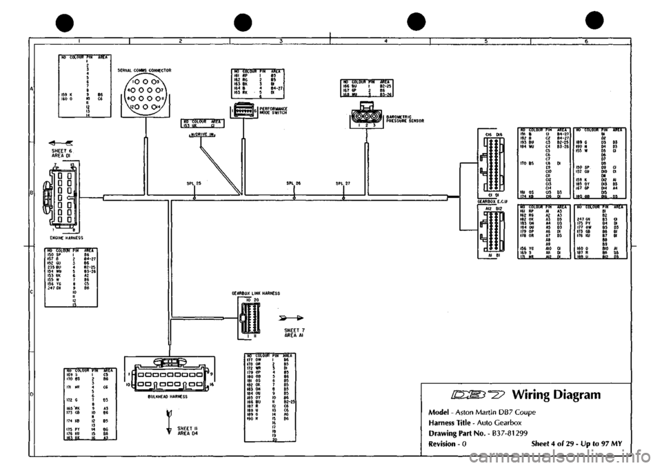
Wiring Diagram
Model - Aston Martin DB7 Coupe
Harness Title - Auto Gearbox
Drawing Part No. - B37-81299
Revision - 0 Sheet 4 of 29 - Up to 97 MY