relays ASTON MARTIN DB7 1997 Workshop Manual
[x] Cancel search | Manufacturer: ASTON MARTIN, Model Year: 1997, Model line: DB7, Model: ASTON MARTIN DB7 1997Pages: 421, PDF Size: 9.31 MB
Page 29 of 421
[n:m3^y
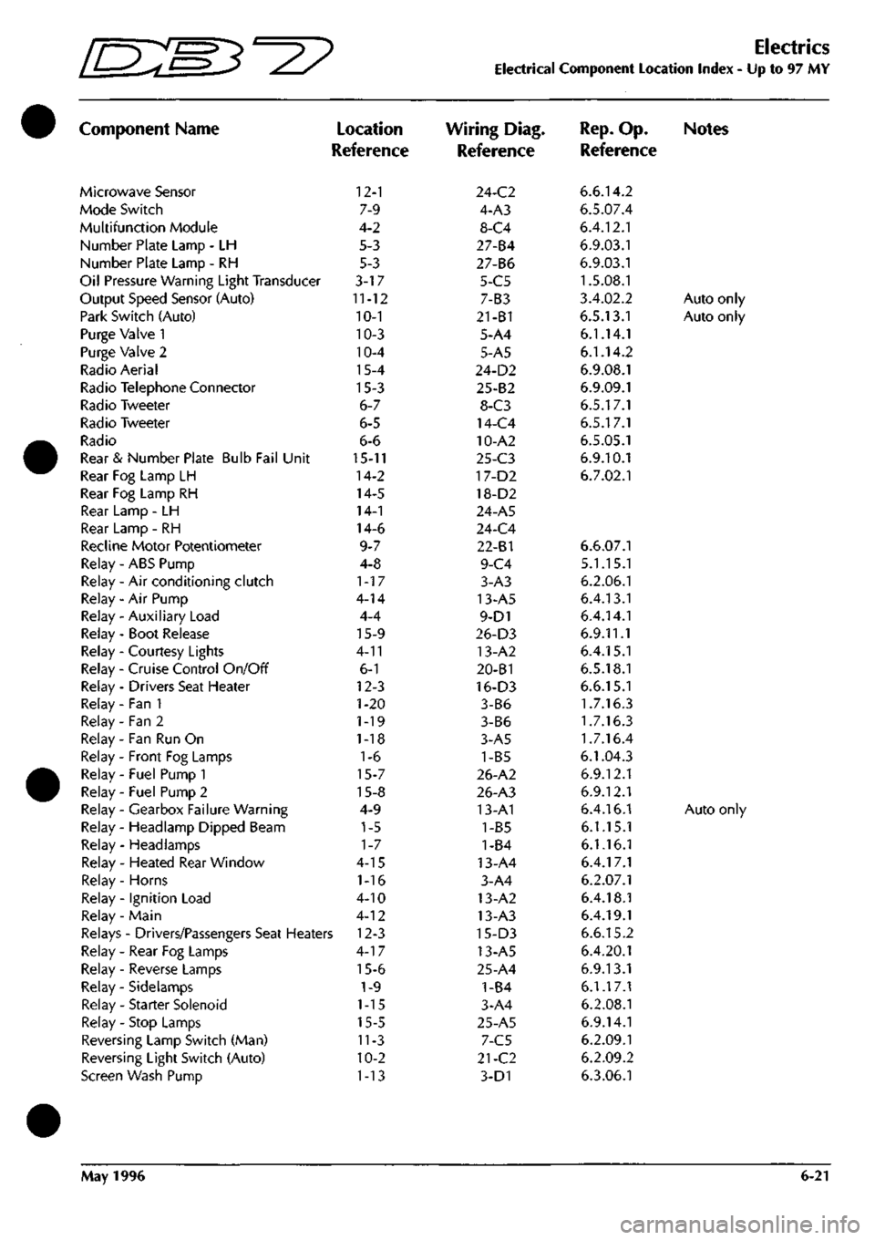
Component Name
Microwave Sensor
Mode Switch
Multifunction Module
Number Plate Lamp - LH
Number Plate Lamp - RH
Oil Pressure Warning Light Transducer
Output Speed Sensor (Auto)
Park Switch (Auto)
Purge Valve 1
Purge Valve 2
Radio Aerial
Radio Telephone Connector
Radio Tweeter
Radio Tweeter
Radio
Rear & Number Plate Bulb Fail Unit
Rear Fog Lamp LH
Rear Fog Lamp RH
Rear Lamp - LH
Rear Lamp - RH
Recline Motor Potentiometer
Relay - ABS Pump
Relay - Air conditioning clutch
Relay - Air Pump
Relay - Auxiliary Load
Relay - Boot Release
Relay - Courtesy Lights
Relay - Cruise Control On/Off
Relay - Drivers Seat Heater
Relay - Fan 1
Relay - Fan 2
Relay - Fan Run On
Relay - Front Fog Lamps
Relay - Fuel Pump 1
Relay - Fuel Pump 2
Relay - Gearbox Failure Warning
Relay - Headlamp Dipped Beam
Relay - Headlamps
Relay - Heated Rear Window
Relay - Horns
Relay - Ignition Load
Relay - Main
)
Location
Reference
12-1
7-9
4-2
5-3
5-3
3-17
11-12
10-1
10-3
10-4
15-4
15-3
6-7
6-5
6-6
15-11
14-2
14-5
14-1
14-6
9-7
4-8
1-17
4-14
4-4
15-9
4-11
6-1
12-3
1-20
1-19
1-18
1-6
15-7
15-8
4-9
1-5
1-7
4-15
1-16
4-10
4-12
Relays - Drivers/Passengers Seat Heaters 12-3
Relay - Rear Fog Lamps
Relay - Reverse Lamps
Relay - Sidelamps
Relay - Starter Solenoid
Relay - Stop Lamps
Reversing Lamp Switch (Man)
Reversing Light Switch (Auto)
Screen Wash Pump
4-17
15-6
1-9
1-15
15-5
11-3
10-2
1-13
Electrics
Electrical Component Location Index - Up to 97 MY
Wiring Diag.
Reference
24-C2
4-A3
8-C4
27-84
27-B6
5-C5
7-B3
21-B1
5-A4
5-A5
24-D2
25-B2
8-C3
14-C4
10-A2
25-C3
17-D2
18-D2
24-A5
24-C4
22-81
9-C4
3-A3
13-A5
9-D1
26-D3
13-A2
20-B1
16-D3
3-B6
3-B6
3-A5
1-B5
26-A2
26-A3
13-A1
1-B5
1-84
13-A4
3-A4
13-A2
13-A3
15-D3
13-A5
25-A4
1-B4
3-A4
25-A5
7-C5
21-C2
3-D1
Rep.
Op. Notes
Reference
6.6.14.2
6.5.07.4
6.4.12.1
6.9.03.1
6.9.03.1
1.5.08.1
3.4.02.2
Auto only
6.5.13.1
Auto only
6.1.14.1
6.1.14.2
6.9.08.1
6.9.09.1
6.5.17.1
6.5.17.1
6.5.05.1
6.9.10.1
6.7.02.1
6.6.07.1
5.1.15.1
6.2.06.1
6.4.13.1
6.4.14.1
6.9.11.1
6.4.15.1
6.5.18.1
6.6.15.1
1.7.16.3
1.7.16.3
1.7.16.4
6.1.04.3
6.9.12.1
6.9.12.1
6.4.16.1
Auto only
6.1.15.1
6.1.16.1
6.4.17.1
6.2.07.1
6.4.18.1
6.4.19.1
6.6.15.2
6.4.20.1
6.9.13.1
6.1.17.1
6.2.08.1
6.9.14.1
6.2.09.1
6.2.09.2
6.3.06.1
May 1996 6-21
Page 131 of 421
Electrics
Relay Location Index - 97 MY
D^^
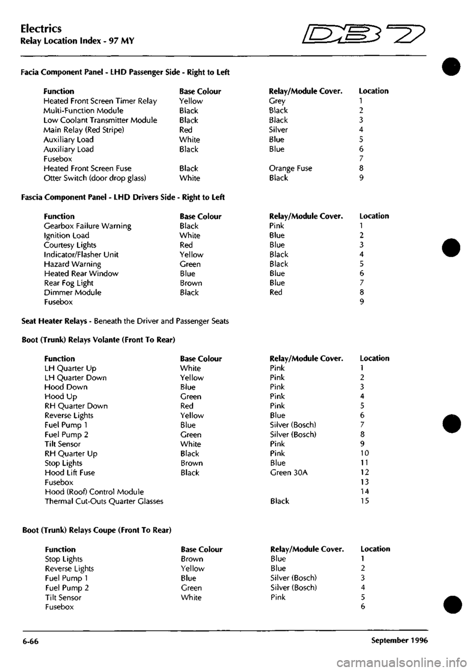
Facia Component Panel
- LHD
Passenger
Function
Heated Front Screen Timer Relay
Multi-Function Module
Low Coolant Transmitter Module
Main Relay (Red Stripe)
Auxiliary Load
Auxiliary Load
Fusebox
Heated Front Screen Fuse
Otter Switch (door drop glass)
Side
-
Right
to
Left
Base Colour
Yellow
Black
Black
Red
White
Black
Black
White
Fascia Component Panel
- LHD
Drivers Side
-
Right
to
Left
Function
Gearbox Failure Warning
Ignition Load
Courtesy Lights
Indicator/Flasher Unit
Hazard Warning
Heated Rear Window
Rear
Fog
Light
Dimmer Module
Fusebox
Base Colour
Black
White
Red
Yellow
Green
Blue
Brown
Black
Relay/Module Cover.
Grey
Black
Black
Silver
Blue
Blue
Orange Fuse
Black
Relay/Module Cover.
Pink
Blue
Blue
Black
Black
Blue
Blue
Red
Location
1
2
3
4
5
6
7
8
9
Location
1
2
3
4
5
6
7
8
9
Seat Heater Relays - Beneath the Driver and Passenger Seats
Boot (Trunk) Relays Volante (Front To Rear)
Function
LH Quarter
Up
LH Quarter Down
Hood Down
Hood
Up
RH Quarter Down
Reverse Lights
Fuel Pump
1
Fuel Pump
2
Tilt Sensor
RH Quarter
Up
Stop Lights
Hood Lift Fuse
Fusebox
Hood (Roof) Control Module
Thermal Cut-Outs Quarter Glasses
Base Colour
White
Yellow
Blue
Green
Red
Yellow
Blue
Green
White
Black
Brown
Black
Relay/Module Cover.
Pink
Pink
Pink
Pink
Pink
Blue
Silver (Bosch)
Silver (Bosch)
Pink
Pink
Blue
Green
30A
Black
Location
1
2
3
4
5
6
7
8
9
10
11
12
13
14
15
Boot (Trunk) Relays Coupe (Front To Rear)
Function
Stop Lights
Reverse Lights
Fuel Pump 1
Fuel Pump 2
Tilt Sensor
Fusebox
Base Colour
Brown
Yellow
Blue
Green
White
6-66
Relay/Module
Blue
Blue
Silver (Bosch)
Silver (Bosch)
Pink
Cover. Location
1
2
3
4
5
6
September
1996
Page 262 of 421
y/--^^^^3^
'—-p "^ Body and Trim
Roof Description
Volante Roof
Description
The system comprises an electrically driven hydraulic pump and two hydraulic rams for raising and lowering the
roof.
The pump is powered via two heavy duty changeover relays. Two further pairs of changeover relays power
the rear quarter windows (one pair for each window). The roof hydraulic pump is protected by a 30A fuse, the
windows by circuit breakers.
An electronic control module (ECM) is actuated by the roof switch on the centre console. The ECM controls the
operation of
both
the roof
and
rear quarter window circuits
so
that they can only be operated in
a
pre-programmed
manned.
When in operation, the ECM provides signals to the roof and to the rear quarter windows.
When the roof
switch
is moved into the open (Roof Down) position, the roof
and
rear windows move together until
approximately four seconds has elapsed. At this time, the ECM will remove power from the rear window circuits,
leaving the roof motor running. The roof motor will stop after 12 seconds (i.e. a further 8 seconds after the rear
window motors stop).
The signals will be removed from the rear window relay after 4 seconds and from the roof relay after 12 seconds
if the roof switch is held in either position for longer than 12 seconds.
In order to comply with legislation, the following features are built into the system:
If the roof switch is operated in either direction and then released before that operation is complete, the roof and
rear quarter windows will stop immediately. If, whilst the system is in operation, the ignition switch
is
turned to the
off position, the system will immediately stop.
If the roof switch is pressed again after pausing during a roof movement, the timing sequence will be as follows:
1.
If the previous direction is selected, the timing recommences from where it left off and will continue to
completion. If the ignition has been turned off, the timing will start from the beginning of its cycle.
2.
If theoppositedirection
is
selected,
the timing sequence will commence
from the beginning
of the newly selected
direction and continue to completion.
Roof and Rear Quarter Light Control
The following diagrams show the component location and the electrical control for the roof and rear quarter light
systems.
May 1996 7-7
Page 287 of 421
Air Conditioning
Temperature Distribution System
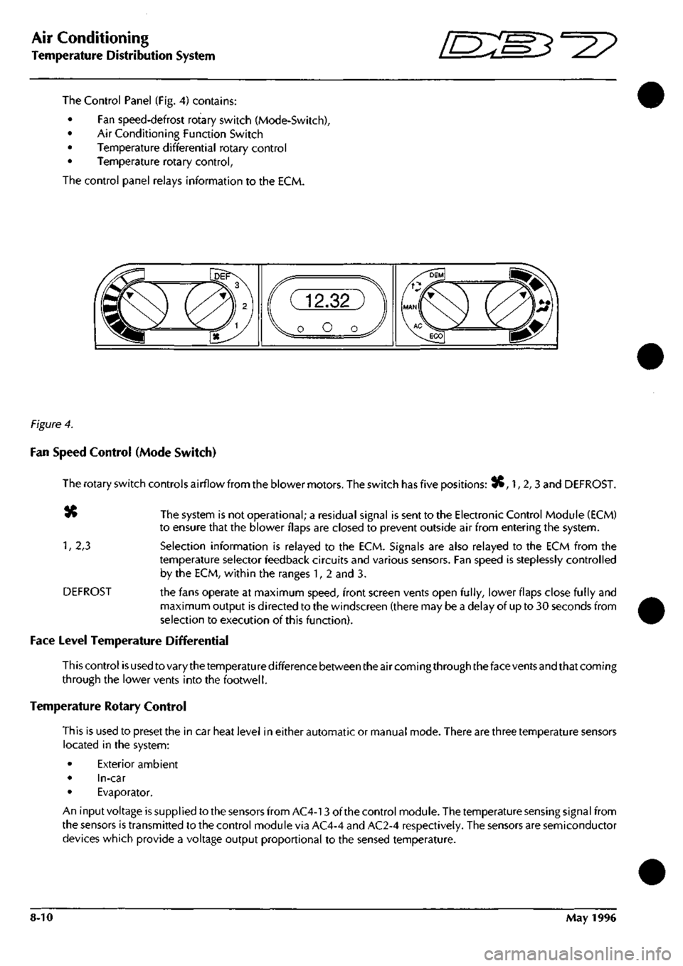
The Control Panel (Fig. 4) contains:
• Fan speed-defrost rotary switch (Mode-Switch),
• Air Conditioning Function Switch
• Temperature differential rotary control
• Temperature rotary control,
The control panel relays information to the ECM.
Figure 4.
Fan Speed Control (Mode Switch)
The rotary switch controls airflow from the blower motors. The switch has five positions: 3C, 1, 2,3 and DEFROST.
«» The system is not operational; a residual signal is sent to the Electronic Control Module (ECM)
to ensure that the blower flaps are closed to prevent outside air from entering the system.
1,
2,3 Selection information is relayed to the ECM. Signals are also relayed to the ECM from the
temperature selector feedback circuits and various sensors. Fan speed is steplessly controlled
by the ECM, within the ranges 1, 2 and 3.
DEFROST the fans operate at maximum speed, front screen vents open fully, lower flaps close fully and
maximum output is directed to the windscreen (there may be a delay of up to 30 seconds from
selection to execution of this function).
Face Level Temperature Differential
This control is used to vary the temperature difference between the air coming through the face vents and that coming
through the lower vents into the footwell.
Temperature Rotary Control
This is used to preset the in car heat level in either automatic or manual mode. There are three temperature sensors
located in the system:
• Exterior ambient
• In-car
• Evaporator.
An input voltage is supplied to the sensors from AC4-13 of the control module. The temperature sensing signal from
the sensors is transmitted to the control module via AC4-4 and AC2-4 respectively. The sensors are semiconductor
devices which provide a voltage output proportional to the sensed temperature.
8-10 May 1996
Page 297 of 421
Air Conditioning
Electronic Control Module r^^?
Description
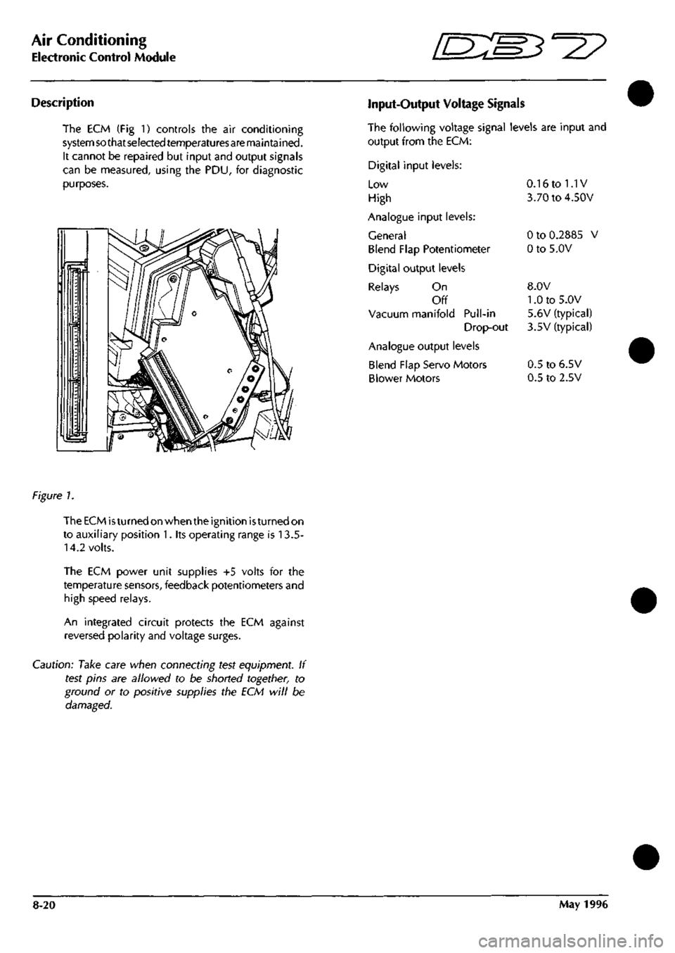
The ECM (Fig 1) controls the air conditioning
system so that selected temperaturesare maintained.
It cannot be repaired but input and output signals
can be measured, using the PDU, for diagnostic
purposes.
Input-Output Voltage Signals
The following voltage signal levels are input and
output from the ECM:
Digital input levels:
Low
High
Analogue input levels:
General
Blend Flap Potentiometer
Digital output levels
Relays On
Off
Vacuum manifold Pull-in
Drop-out
Analogue output levels
Blend Flap Servo Motors
Blower Motors
0.16 to 1.1V
3.70 to 4.50V
0 to 0.2885 V
0 to 5.0V
8.0V
1.0 to 5.0V
5.6V (typical)
3.5V (typical)
0.5 to 6.5V
0.5 to 2.5V
figure 1.
The ECM
is
turned on when the ignition
is
turned on
to auxiliary position 1. its operating range is 13.5-
14.2 volts.
The ECM power unit supplies +5 volts for the
temperature sensors, feedback potentiometers and
high speed relays.
An integrated circuit protects the ECM against
reversed polarity and voltage surges.
Caution: Take care when connecting test equipment. If
test pins are allowed to be shorted together, to
ground or to positive supplies the ECM will be
damaged.
8-20 May 1996
Page 308 of 421
"3^2?
Air Conditioning
System Fault Diagnosis
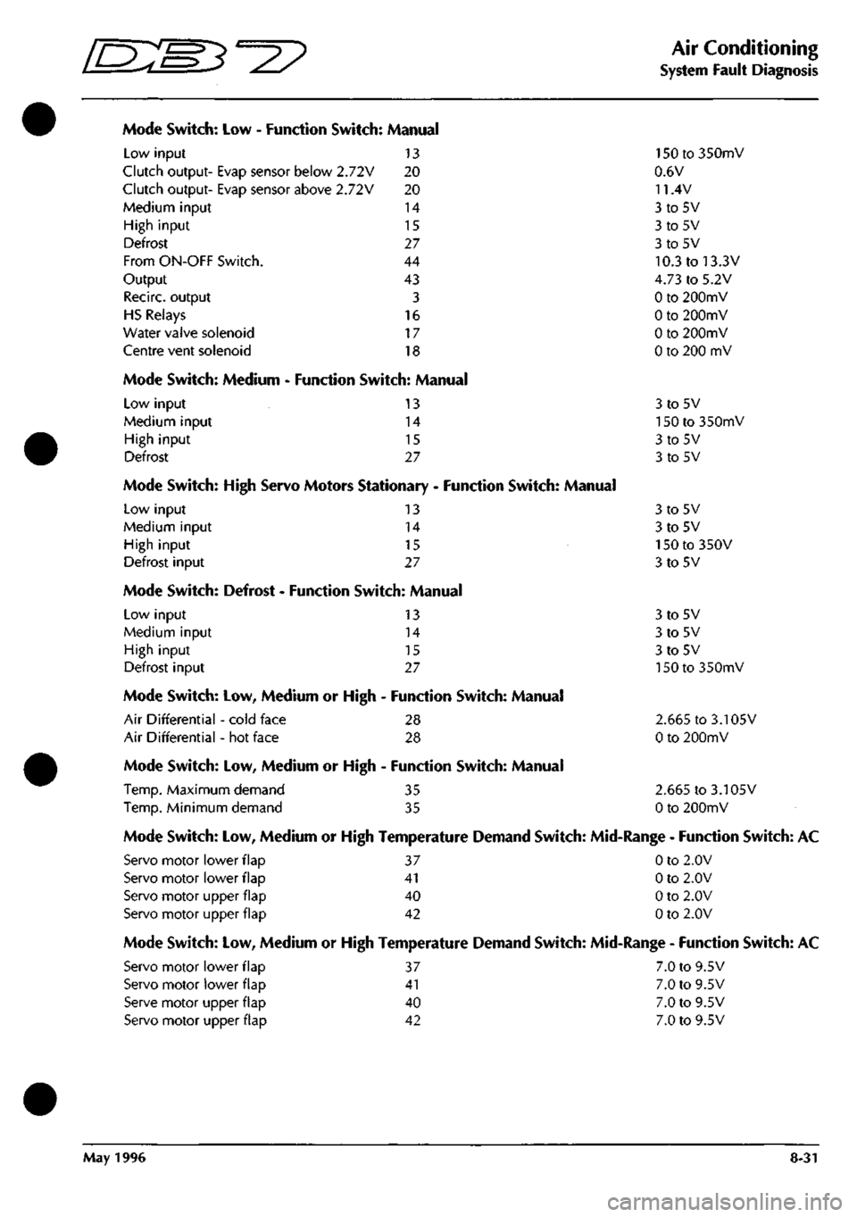
Mode Switch: Low - Function Switch: Manual
Low input 13
Clutch output- Evap sensor below 2.72V 20
Clutch output- Evap sensor above 2.72V 20
Medium input 14
High input 15
Defrost 27
From ON-OFF Switch. 44
Output 43
Recirc. output 3
HS Relays 16
Water valve solenoid 17
Centre vent solenoid 18
Mode Switch: Medium - Function Switch: Manual
Low input
Medium input
High input
Defrost
13
14
15
27
Mode Switch: High Servo Motors Stationary - Function Switch: Manual
Low input 13
Medium input 14
High input 15
Defrost input 27
Mode Switch: Defrost - Function Switch: Manual
Low input
Medium input
High input
Defrost input
13
14
15
27
Mode Switch: Low, Medium or High - Function Switch: Manual
Air Differential - cold face 28
Air Differential - hot face 28
Mode Switch: Low, Medium or High - Function Switch: Manual
Temp.
Maximum demand 35
Temp.
Minimum demand 35
150 to 350mV
0.6V
11.4V
3to5V
3to5V
3to5V
10.3 to 13.3V
4.73 to 5.2V
0 to 200mV
0 to 200mV
0 to 200mV
0 to 200 mV
3to5V
150 to 350mV
3to5V
3to5V
3to5V
3to5V
150 to 350V
3to5V
3to5V
3to5V
3to5V
150 to 350mV
2.665 to 3.105V
0 to 200mV
2.665 to 3.105V
0 to 200mV
Mode Switch: Low, Medium or High Temperature Demand Switch: Mid-Range - Function Switch: AC
Servo motor lower flap 37 0 to 2.0V
Servo motor lower flap 41 0 to 2.0V
Servo motor upper flap 40 0 to 2.0V
Servo motor upper flap 42 0 to 2.0V
Mode Switch: Low, Medium or High Temperature Demand Switch: Mid-Range - Function Switch: AC
Servo motor lower flap 37 7.0 to 9.5V
Servo motor lower flap 41 7.0 to 9.5V
Serve motor upper flap 40 7.0 to 9.5V
Servo motor upper flap 42 7.0 to 9.5V
May 1996 8-31
Page 309 of 421
Air Conditioning
System Fault Diagnosis D^
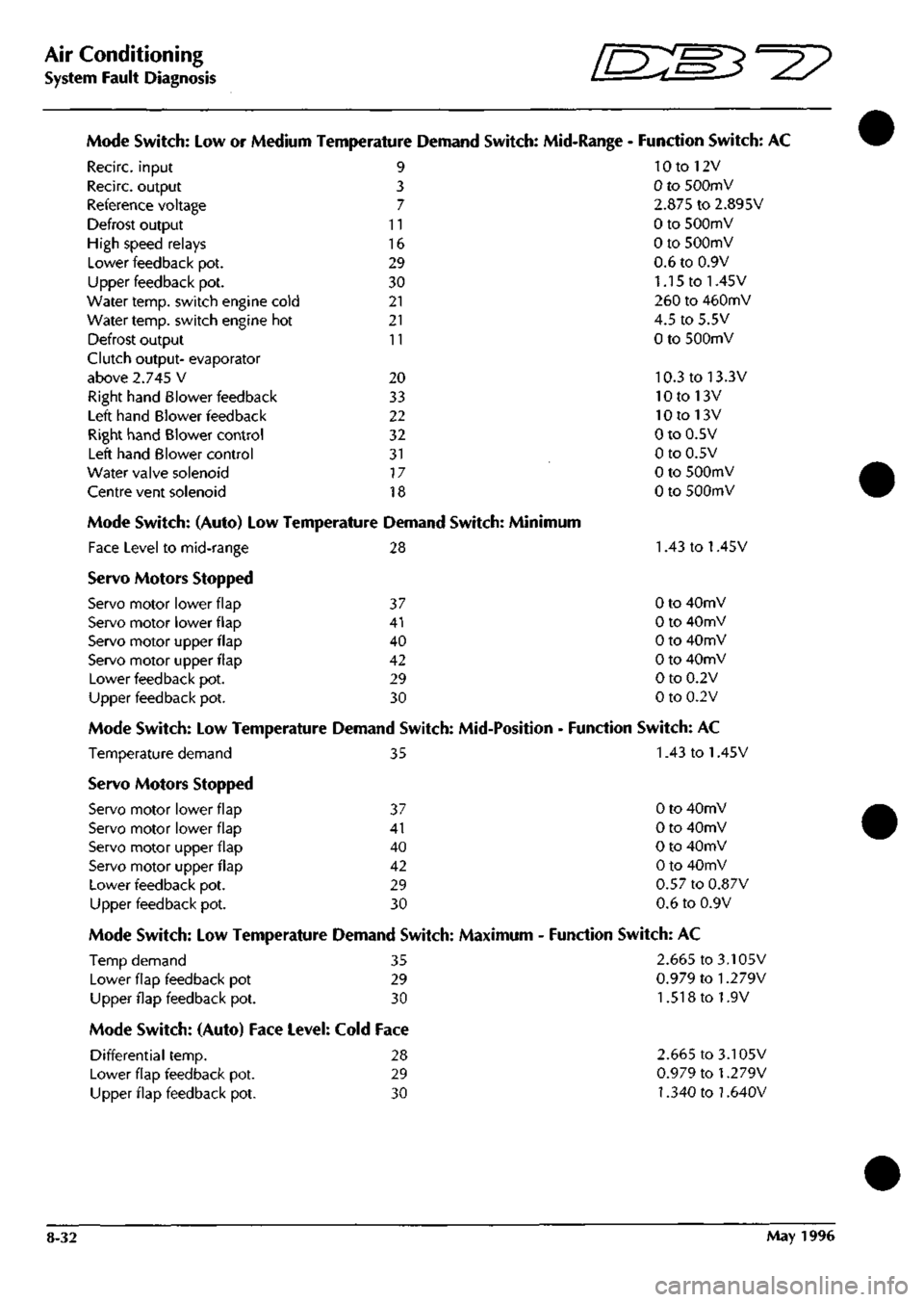
Mode Switch: Low or Medium Temperature Demand Switch: Mid-Range - Function Switch: AC
10 to 12V
0 to SOOmV
2.875 to 2.895V
0 to 500mV
0 to 500mV
0.6 to 0.9V
1.15 to 1.45V
260 to 460mV
4.5 to 5.5V
0 to 500mV
10.3 to 13.3V
10 to 13V
10 to 13V
0 to 0.5V
0 to 0.5V
0 to 500mV
0 to SOOmV
Recirc. input
Recirc. output
Reference voltage
Defrost output
High speed relays
Lower feedback pot.
Upper feedback pot.
Water temp, switch engine cold
Water temp, switch engine hot
Defrost output
Clutch output- evaporator
above 2.745 V
Right hand Blower feedback
Left hand Blower feedback
Right hand Blower control
Left hand Blower control
Water valve solenoid
Centre vent solenoid
9
3
7
11
16
29
30
21
21
11
20
33
22
32
31
17
18
Mode Switch: (Auto) Low Temperature Demand Switch: Minimum
Face Level to mid-range 28 1.43 to 1.45V
Servo Motors Stopped
Servo motor lower flap 37 0 to 40mV
Servo motor lower flap 41 0 to 40mV
Servo motor upper flap 40 0 to 40mV
Servo motor upper flap 42 0 to 40mV
Lower feedback pot. 29 0 to 0.2V
Upper feedback pot. 30 0 to 0.2V
Mode Switch: Low Temperature Demand Switch: Mid-Position - Function Switch: AC
Temperature demand 35 1.43 to 1.45V
Servo Motors Stopped
Servo motor lower flap 37 0 to 40mV
Servo motor lower flap 41 0 to 40mV
Servo motor upper flap 40 0 to 40mV
Servo motor upper flap 42 0 to 40mV
Lower feedback pot. 29 0.57 to 0.87V
Upper feedback pot. 30 0.6 to 0.9V
Mode Switch: Low Temperature Demand Switch: Maximum - Function Switch: AC
Temp demand 35 2.665 to 3.105V
Lower flap feedback pot 29
Upper flap feedback pot. 30
0.979 to
1.279V
1.518 to 1.9V
Mode Switch: (Auto) Face Level: Cold Face
Differential temp. 28
Lower flap feedback pot. 29
Upper flap feedback pot. 30
2.665 to 3.105V
0.979 to
1.279V
1.340 to
1.640V
8-32 May 1996
Page 310 of 421
^7?
Air Conditioning
System Fault Diagnosis
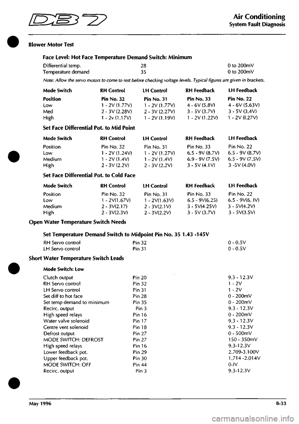
Blower Motor Test
Face Level: Hot Face Temperature Demand Switch: Minimum
Differential temp. 28 0 to 200mV
Temperature demand 35 0 to 200mV
Hote:
Allow
the servo motors
to
come to rest before checking voltage
levels.
Typical figures are given
in
brackets.
Mode Switch
Position
Low
Med
High
RH Control
Pin No. 32
1 - 2V (1.77V)
3V (2.28V)
2v
(1.1
7V)
Set Face Differential Pot. to Mid Point
Mode Switch RH Control
Position Pin No. 32
Low 1 - 2V (1.24V)
Medium 1 - 2V (1.4V)
High 2-3V(2.2V)
Set Face Differential Pot. to Cold Face
Mode Switch
Position
Low
Medium
High
RH Control
Pin No. 32
1 - 2V(1.67V)
2 - 3V(2.17)
2 - 3V(2.3V)
LH Control
Pin No. 31
1 -2V(1.77V)
2 - 3V (2.27V)
1 - 2V (1.19V)
LH Control
Pin No. 31
1 - 2V (1.27V)
1 - 2V (1.4V)
2 - 3V (2.2V)
LH Control
Pin No. 31
1 - 2V(1.63V)
2-3V(2.1V)
2 - 3V(2.2V)
RH Feedback
Pin No. 33
4 - 6V (5.8V)
3 - 5V (3.7V)
1 - 2V (1.22V)
RH Feedback
Pin No. 33
6.5 - 9V (8.7V)
6.9 - 9V (7.5V)
3-5V(4.1V)
RH Feedback
Pin No. 33
6.5 - 9V(6.25)
3 - 5V(4.25V)
3 - 5V (3.7V)
Open Water Temperature Switch Needs
Set Temperature Demand Switch to Midpoint Pin No. 35 1.43 -145V
RH Servo control Pin 32
LH Servo control Pin 31
Short Water Temperature Switch Leads
Mode Switch: Low
Clutch output
RH Servo control
LH Servo control
Set d iff to hot face
Set temp demand to minimum
Recirc. output
High speed relays
Water valve solenoid
Centre vent solenoid
Defrost output
MODE SWITCH: DEFROST
High speed relays
Lower feedback pot.
Upper feedback pot.
MODE SWITCH: OFF
Recirc. output
Pin 20
Pin 32
Pin 31
Pin 28
Pin 35
Pin 3
Pin 16
Pin 17
Pin 18
Pin 27
Pin 27
Pin 16
Pin 29
Pin 30
Pin 44
Pin 3
LH Feedback
Pin No. 22
4 - 6V (5.63V)
3 - 5V (3.4V)
1 -2V (1.27V)
LH Feedback
Pin No. 22
6.5 - 9V (8.7V)
6.5 - 9V (7.5V)
3 -5V (4.0V)
LH Feedback
Pin No. 22
6.5 - 9V(6. IV)
3 - 5V(4.2V)
3 - 5V(3.SV)
0.5V
0.5V
9.3-12.3V
1 -2V
1 -2V
0 - 200mV
0 - 200mV
9.3-12.3V
0 - 200mV
9.3-12.3V
9.3-12.3V
0 - 500mV
150-350mV
9.3-12.3V
2.709-3.1 OOV
1.714-2.014V
0-IV
9.3-12.3V
May 1996 8-33