7-1 ASTON MARTIN V8 VANTAGE 2010 Workshop Manual
[x] Cancel search | Manufacturer: ASTON MARTIN, Model Year: 2010, Model line: V8 VANTAGE, Model: ASTON MARTIN V8 VANTAGE 2010Pages: 947, PDF Size: 43.21 MB
Page 3 of 947
Contents
Issue 5, January 2010 Workshop Manual 0-0-3
V8 Vantage Workshop Manual
Contents
IntroductionWelcome .............................................................. 0-0-6
Safety Precautions ................................................. 0-0-7
Lifting and Jacking ................................................. 0-0-9
Vehicle Recovery ................................................ 0-0-10
Vehicle Identification Number ............................ 0-0-11
Body System (01.00) Body Structure (01.01) .......................................... 1-1-4
Front End System (01.02) ...................................... 1-2-1
Body Closures (01.03) ........................................... 1-3-1
Interior Trim (01.05) ............................................. 1-4-1
Exterior Trim (01.08) ............................................. 1-8-1
Mirrors (01.09) ...................................................... 1-9-1
Seating (01.10).................................................... 1-10-1
Glass, Frame and Mechanism (01.11) .................. 1-11-1
Instrument Panel (IP) (01.12) . .............................. 1-12-1
Handles and Lock Mechanisms (01.14) ............... 1-14-1
Wipers and Washer System (01.16)..................... 1-16-1
Convertible Roof and Roof Opening
Subsystem (01.17)................ ...............................1-17-1
Bumpers (01.19) ................................................. 1-19-1
Restraining Devices (01.20) .... ............................. 1-20-1
Frame and Mounting (02.00) Subframes (02.03) ................................................. 2-1-2
Engine System (03.00) Engine Assembly....................................................3-0-3
Engine Structure (03.01)........................................ 3-1-1
Lubrication System (03.02).................................... 3-2-1
Cooling System (03.03) ......................................... 3-3-1
Fuel Charging System (03.04) ................................ 3-4-1
Accessory Drive System (03.05)............................. 3-5-1
Engine Cranking System (03. 06) ............................ 3-6-1
Valve Train (03.09) ............................................... 3-9-1
Engine Sealing (03.10)......................................... 3-10-1
Power Conversion (03.11)................................... 3-11-1
Evaporative Emissions (03.13) ............................. 3-11-1
Engine Management System (0 3.14).................... 3-14-1
Throttle Control (03.16) ...... ................................ 3-16-1
Foot Operated Control (03.18)............................ 3-18-1
Suspension (04.00) Road Wheel Alignment (04.00) ............................. 4-0-2
Front Suspension (04.01)....................................... 4-1-1
Rear Suspension (04.02)........................................ 4-2-1
Shock Absorber System (04.03) ............................. 4-3-1
Road Wheels and Tyres (04.04) ............................ 4-4-1
Driveline (05.00) Driveshaft (05.01) ................................................. 5-1-2
Halfshafts (05.05) .................................................. 5-2-1 Brake System (06.00)
Front Disc Brake (06.03) ....................................... 6-3-2
Rear Disc Brakes (06.04) ....................................... 6-4-1
Hand Brake (06.05) .............................................. 6-5-1
Brake Actuation System (06.06 ) ............................ 6-6-1
Power Brake System (06.07) ................................. 6-7-1
Anti-lock Braking System (06.09)........................... 6-9-1
Transmission (07.00) Transmission Cooling (07.02) ................................ 7-0-2
Manual Transmission (07.03) ................................ 7-3-1
Automatic Control System (07.05)......................... 7-5-1
Manual Control System (07.06) ............................. 7-6-1
Automatic Shifting Subsytem (07.11) .................. 7-11-1
Clutch (08.00) Clutch Controls (08.02) ......................................... 8-1-2
Exhaust (09.00) Exhaust Overview ................................................. 9-1-2
Silencer Assembly (09.01) ..................................... 9-1-3
Pipes and Supports (09.03) ................................... 9-2-1
Exhaust Protection (09.04) .................................... 9-3-1
Fuel (10.00) Fuel Tank and Lines (10.01) ................................ 10-1-2
Steering (11.00) Steering Gear (11.01) .......................................... 11-1-2
Power Steering (11.02)........................................ 11-2-1
Steering Column (11.04) ..................................... 11-4-1
Steering Column Switches (1 1.05) ....................... 11-5-1
Steering Wheel (11.06) ....................................... 11-6-1
Climate Control (12.00) Body Ventilation system (12.01) .......................... 12-1-2
Heater System (12.02) ........................................ 12-2-1
Air Conditioning (A/C) System (12.03) ................. 12-3-1
Information, Gauge and Warning (13.00) Instrument Cluster (13.01) .................................. 13-1-2
Power Supply (14.00) Battery System (14.01) ........................................ 14-1-2
Alternator and Regulator System (14.02) ............. 14-2-1
Vehicle Entertainment (15.00) Audio System (15.01)................................ ..........15-1-2
Antenna (15.02).................................................. 15-2-1
Vacuum Distribution (16.00) Body Vacuum System (16.01) ............................. 16-1-2
Lighting (17.00) Front Lights (17.01) ............................................. 17-1-2
Interior Lighting (17.02) ...................................... 17-2-1
Rear Lights (17.03) .............................................. 17-3-1
Lighting Mechanisms (17.04). .............................. 17-4-1
Page 13 of 947
Issue 5, January 2010 Workshop Manual 1-1-1
Body System (01.00)
Contents
Body Structure (01.01)........................................... 1-1-4Overview ................................................................ 1-4
Specifications.......................................................... 1-4
Maintenance ........................................................... 1-5Right Side Front Crush Bar for the Body
Reinforcement - Remove and Install ....................... 1-5
Left Side Front Crush Bar for the Body
Reinforcement - Remove and Install ....................... 1-5
Front Crush Brace - Remove and Install .................. 1-5
Front End (01.02) ................................................... 1-2-1 Front Wings ............................................................ 2-1Specifications ......................................................... 2-1
Maintenance ........................................................... 2-1 Radiator Closing Panel - Remove and Install ........... 2-1
Centre Undertray - Remove and Install
(Roadster Only) ..................................................... 2-1
Front Undertray-Remove and Install ....................... 2-2
Rear Undertray - Renew (Coupe only).................... 2-2
Rear Undertray - Renew (Roadster only) ................ 2-2
Install ..................................................................... 2-2.............................................................................. 2-2
Undertray, Vehicle Set - Renew ............................. 2-2
RH/LH Front Wheel Arch Liner - Renew ................ 2-2
RH/LH Rear Wheel Arch Liner - Renew ................. 2-3
RH Front Wing Panel Assembly - Renew ................ 2-4
LH Front Wing Panel Assembly - Renew ................ 2-6
Body Closures (01.03) ........................................... 1-3-1 Specifications.......................................................... 3-1Doors .................................................................... 3-1
Tailgate .................................................................. 3-1
Bonnet................................................................... 3-2
Maintenance ........................................................... 3-2 LH/RH Door Assembly-Renew ............................... 3-2
RH/LH Door Assembly-Remove/Refit ..................... 3-6
Front Door Hinge (One Side) - Renew ................... 3-6
Front Door Check Arm Assembly - Renew ............. 3-7
Boot Lid Assembly - Renew (Roadster Only) ........... 3-7
Boot Lid Hinge Assembly (Pair) - Renew
(Roadster Only) .................................................... 3-10
Boot Gas Strut (Pair) - Renew (Roadster Only) ...... 3-11
Boot Lid Striker Assembly - Renew
(Roadster Only) .................................................... 3-11
Exterior Boot Lid Switch Release - Renew
(Roadster Only) .................................................... 3-12
Tailgate Assembly - Renew ................................... 3-12
Tailgate Hinge Assembly (Pair) - Renew ................ 3-13
Hood Assembly - Renew ...................................... 3-14
Hood Hinge Assembly (Vehicle Set) - Renew ....... 3-14
Interior Trim (01.05).............................................. 1-4-1 Maintenance ........................................................... 4-1Rear Centre Console - Renew ................................ 4-1
Headlining - Renew (Roadster Only) ...................... 4-1
Header Panel As sembly - Renew
(Excluding Roadster)............................................... 4-6 Header Panel Assembly - Renew (Roadster Only)... 4-7
Front Header Console Assembly - Renew............... 4-7
RH/LH Upper Rear Pillar Panel Assembly
- Renew ................................................................. 4-8
RH Sun Visor - Renew ........................................... 4-8
LH Sun Visor - Renew ............................................ 4-8
Door Trimboard Assembly - Renew ....................... 4-9
Door Trimboard Assembly
- Remove for Access/Refit ...................................... 4-9
Lower Quarter Trim Panel Assembly - Renew
(Roadster Only)...................................................... 4-9
Side Carpet Kit (RHD) - Renew ............................ 4-11
Side Carpet Kit (LHD) - Renew ............................ 4-12
Top Rear Console Fini
sher Panel Assembly
- Renew (Roadster Only) ...................................... 4-14
RH/LH Bodyside Rear Trim Panel Assembly
- Renew (Roadster Only) ...................................... 4-14
Tonneau to Body Weatherstrip Assembly
- Renew (Roadster Only) ...................................... 4-15
Door Trim Weather Strip Assembly - Renew
(Roadster Only).................................................... 4-16
Exterior Trim (01.08) ............................................. 1-5-1 Maintenance ........................................................... 5-1RH/LH Applique Sill - Renew ................................. 5-1
RH Wing Side Strake - Renew................................ 5-2
LH Wing Side Strake - Renew ................................ 5-2
Channel Assembly Divider Bar - Renew ................. 5-2
Windshield Header Finisher - Renew
(Roadster Only)...................................................... 5-3
Mirrors (01.09) ...................................................... 1-6-1 Specifications ......................................................... 6-1
Maintenance ........................................................... 6-1RH Door Mirror Assembly - Renew ........................ 6-1
LH Door Mirror Assembly - Renew ........................ 6-1
Seating (01.10)....................................................... 1-7-1 Description ............................................................. 7-1Heated Seats ......................................................... 7-1
Specifications ........................................................ 7-1
Maintenance ........................................................... 7-1 RH/LH Front Seat - Remove and Install .................. 7-1
Front Seat Squab Cover Assembly
(Each, Pre-08MY) - Remove and Install .................. 7-1
Front Seat Squab Cover Assembly
(Each, from 08MY) - Remove and Install................. 7-3
Front Seat Cushion Cover Assembly (Each)
- Renew ................................................................. 7-3
6-Way Height Adjuster (Inc. Motors) - Renew ........ 7-4
Squab Motor Kit - Renew....................................... 7-6
Lumbar Support Kit - Renew .................................. 7-7
Side Airbag - Renew .............................................. 7-8
Front Seat Buckle Assembly - Renew...................... 7-9
Valance Heater and Lumbar Switch Assembly
- Renew ................................................................. 7-9
Seat Harness Kit - Renew ..................................... 7-10
Page 14 of 947
1-1-2 Workshop Manual Issue 5, January 2010
RH/LH Seat Switchpack Assembly - Renew...........7-13
Lumbar Pump for the Front Seat (From 08MY)
- Remove and Install.............................................7-13
Lumbar Valve for the Front Seat (From 08MY)
- Remove and Install.............................................7-14
Lumbar Bladder for the Front Seat (From 08MY)
- Remove and Install.............................................7-14
Glass, Frame and Mechanism (01.11) .................. 1-8-1 Description .............................................................8-1 Frameless doors......................................................8-1
Specifications .........................................................8-1
Maintenance ...........................................................8-1 Glass Regulator - Renew .........................................8-1
RH/LH Door Glass - Renew ....................................8-2
Door Glass - Adjust/Reset .......................................8-3
Front Windshield - Renew ......................................8-3
Rear Windshield - Renew .......................................8-4
Quarter Window Glass - Renew .............................8-6
Passenger Window Lift Switch - Renew ..................8-6
Driver Window Lift Switch - Renew........................8-7
Instrument Panel (IP) (01.12)................................ 1-9-1 Specifications ..........................................................9-1
Maintenance ...........................................................9-1 Instrument Panel - Renew ......................................9-1
Airbag Panel and Door Assembly - Renew ..............9-6
Glovebox Assembly - Renew ..................................9-6
Instrument Centre Panel Asse mbly - Renew............9-7
Knee Protector - Renew .........................................9-7
Instrument Panel As sembly - Renew .......................9-7
Cluster Bezel Panel - Renew .................................9-10
Driver Panel Assembly - Renew ............................9-10
Instrument Panel Bezel A ssembly (With Sat. Nav.)
- Renew ...............................................................9-11
Instrument Panel Bezel Assembly
(Without Sat. Nav.) - Renew .................................9-11
Rear Console Panel Assembly - Renew .................9-12
Armrest Pad Assembly - Renew ............................9-13
Console Panel Assembly - Renew .........................9-13
RH/LH Rear Console Pa nel Assembly - Renew
(Roadster Only) ....................................................9-13
Centre Console Panel - Remove and Install
(Coupe Only) .......................................................9-15
Centre Console Panel - Remove and Install
(Roadster Only) ....................................................9-19
RH/LH Lower Quarter Panel Assembly - Renew
(Roadster Only) ....................................................9-29
Handles and Lock Mechanisms (01.14) .............. 1-10-1 Description ...........................................................10-1 Vehicle Key/Remote Transmitter...........................10-1
Central Locking System ........................................10-1
Remote Transmitter ..............................................10-1
Fuel Filler Assembly ..............................................10-1
Boot Emergency Release ....... ...............................10-1
Specifications ........................................................10-2
Maintenance .........................................................10-2 Ignition Cylinder Lock - Re new.............................10-2
RH/LH Front Door Latch As sembly - Renew .........10-2
Bonnet Latch Assembly - Renew...........................10-3
Hood Release Cable Assembly - Renew (Roadster Only) .................................................... 10-3
Bonnet Secondary Latch Asse
mbly - Renew ......... 10-4
Tailgate Latch and Cable Assembly - Renew ......... 10-4
Fuel Filler Actuator Assembly - Renew
(Roadster Only) .................................................... 10-4
Fuel Filler Release Cable - Renew (Roadster Only) 10-5
Fuel Flap Release Switch - Renew ........................ 10-6
RH/LH Tonneau Latch Motor - Renew
(Roadster Only) .................................................... 10-7
RH/LH Tonneau Latch - Renew (Roadster Only) ... 10-7
RH/LH Tonneau Cover Striker Assembly
- Renew (Roadster Only) ...................................... 10-8
Tailgate Latch Assembly-Renew (Roadster Only) ... 10-8
Wipers and Washer System (01.16) ....................1-11-1 Headlamp Washing .............................................. 11-1
Specifications ........................................................ 11-2
Maintenance ......................................................... 11-2 Windscreen Wiper Motor As sembly - Renew ....... 11-2
Wiper Linkage Assembly - Renew ........................ 11-2
Windshield Wash Tube - Renew .......................... 11-2
Windscreen Reservoir and Motor Assembly
- Remove and Install ............................................ 11-3
Low Level Water Sensor - Remove and Install ...... 11-4
Headlamp Wash Motor and Pump Assembly
- Renew ............................................................... 11-5
Headlamp Wash Tube Assembly - Renew ............ 11-5
Washer Fluid Reservoir - Renew........................... 11-6
Convertible Roof and Roof Opening Subsystem
(01.17)..................................................................1-12-1 System Description .............................................. 12-1
Maintenance ......................................................... 12-2 Hood Assembly-Renew ........................................ 12-2
Canopy Cover - Renew ........................................ 12-5
Header Latch Motor - Renew ............................... 12-9
Hydraulic Main Actuator Cy linder - Renew .......... 12-9
Hydraulic Tensrod Cylinder - Renew .................. 12-10
Hydraulic Tonneau Cylinder - Renew................. 12-11
Convertible Top ECU - Renew ........................... 12-13
Hydraulic Pump - Renew ................................... 12-13
Hydraulic Lock Valve - Renew............................ 12-16
RH/LH Front Cantrail Seal - Spare Part
- Renew ............................................................. 12-18
RH/LH Front Cantrail Seal Spare Part Kit
- Renew ............................................................. 12-18
RH/LH Middle Cantrail Seal Spare Part
- Renew ............................................................. 12-18
RH/LH Middle Cantrail Seal Spare Part Kit
- Renew ............................................................. 12-19
Rear Seal Spare Part Assembly Kit - Renew ......... 12-20
LH Fully Automatic Latching Kit - Renew............ 12-21
RH Fully Automatic Latching Kit - Renew ........... 12-22
Convertible Roof Hydraulic Pump
- Check Fluid Level ............................................ 12-23
Cantrail Cover Trim - Renew .............................. 12-25
B-Post Trim Cover - Renew ................................ 12-25
Tonneau Cover - Renew .................................... 12-27
LH Front Main Hydraulic Cylinder Pipe
- Renew ............................................................. 12-29
LH Rear Main Hydraulic Cylinder Pipe
Page 67 of 947

Seating (01.10)
Body System (01.00)
Issue 4, November 2008 Workshop Manual 1-7-1
Body System (01.00)
Seating (01.10)
Description
The front seats are installed with the following features:
• Integral side airbags
•Head restraints
• Safety belt reel pretensioner
• Electrically adjustable seat positioning and lumbar support
• Heated seat (optional)
Heated Seats
The heated seat system comprises:
• Heated seat switches
• Backrest heater element
• Cushion heater element and thermostat
The heated seat function permits the electrical heating of the
seat back and cushion on the driver and front passenger
seats. The heating system of each seat is selected by separate
switches located on the inside of each seat base.
Once the heated seat function has been activated, it will
operate until one of the following conditions have been
satisfied:
• A fixed period of time has expired (10 minutes)
• If the engine is not running and the ignition key is removed
• A malfunction is detected by the heated seat module
Confirmation that the heated seat function is active is
indicated by the illumination of an amber light on the
switch.
Specifications Maintenance
RH/LH Front Seat - Remove and Install
Remove
1. Power seat fully forward.
2. Remove bolts (x2), securing rear of seat to seat rails.
3. Power seat fully rearwards.
4. Disconnect vehicle battery.
5. Remove bolt securing se
at belt to seat frame.
6. Remove bolts (x2), securing front of seat to seat rails.
7. Tip the seat forwards and disconnect multiplugs (x4).
8. Protect sill plate and trim prior to seat removal.
9. With assistance, remove seat assembly.
Install
1. With assistance, Install seat in the vehicle.
2. Position seat belt to seat frame, install and torque tighten bolt.
3. Tip the seat forwards and connect multiplugs (x4).
4. Position seat onto seat rails.
5. Remove sill plate protection.
6. Connect vehicle battery.
7. Install front bolts (x2. Power seat forward and install rear bolts (x2). Torque tighten bolts (x4).
Front Seat Squab Cover Assembly (Each,
Pre-08MY) - Remove and Install
Remove
1. Remove seat (see Workshop Manual procedure 01.10.AB Seat Assembly - Front - LH - Remove for
Access and Refit).
Torque Figures
DescriptionNm
Seat mountings 20-25
Seatbelt 15-20
Repair Operation Time (ROT)
Repair Operation Time (ROT)
Page 76 of 947
Seating (01.10)
Body System (01.00)1-7-10 Workshop Manual Issue 4, November 2008
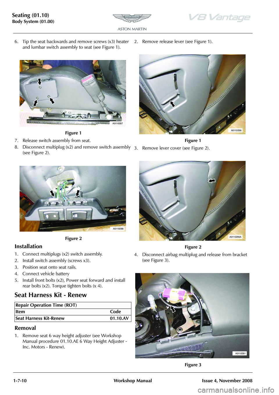
6. Tip the seat backwards and remove screws (x3) heater and lumbar switch assembly to seat (see Figure 1).
7. Release switch assembly from seat.
8. Disconnect multiplug (x2) and remove switch assembly (see Figure 2).
Installation
1. Connect multiplugs (x2) switch assembly.
2. Install switch assembly (screws x3).
3. Position seat onto seat rails.
4. Connect vehicle battery
5. Install front bolts (x2), Power seat forward and install rear bolts (x2). Torque tighten bolts (x 4).
Seat Harness Kit - Renew
Removal
1. Remove seat 6 way height adjuster (see Workshop Manual procedure 01.10.AE 6 Way Height Adjuster -
Inc. Motors - Renew). 2. Remove release lever (see Figure 1).
3. Remove lever cover (see Figure 2).
4. Disconnect airbag multiplu
g and release from bracket
(see Figure 3).
Figure 1
Figure 2
Repair Operation Time (ROT)
A0110287
A0110286
Figure 1
Figure 2
Figure 3
A0110296
A0110296A
A0110281
Page 77 of 947

Seating (01.10)
Body System (01.00)
Issue 4, November 2008 Workshop Manual 1-7-11
5. Remove fixing multiplug bracket, move aside.
6. Remove (slide down) airbag module (bolt x1).
7. Release cover from seat back shell (studs x2 velcrox2).
8. Release cover from seat back shell (strip x2 /clips x9).
9. Release cover from bottom of seat back shell.
10. Push cover through to front of seat, release strip and ease from foam (velcro strips).
11. Disconnect heater multip lug and remove squab foam
(see Figure 4).
12. Remove seat back shell (rivets x4) (see Figure 5). 13. Disconnect lumbar and sq
uab motor multiplugs (see
Figure 6).
14. Remove earth header (nut and bolt) and release harness from clips (x2) (see Figure 7).
Figure 4
Figure 5
A0110293
A0110285
Figure 6
Figure 7
A0110284
A0110295
Page 78 of 947

Seating (01.10)
Body System (01.00)1-7-12 Workshop Manual Issue 4, November 2008
15. Drill out pop rivets from release rod support, and feed harness past rod (see Figure 8).
16. Release harness from clips (x3) and seat cover loop, feed through seat frame (see Figure 9). 17. Disconnect cushion heater
multiplug (see Figure 10).
18. Release cushion cover from frame, feed harness through cover and foam (see Figure 11).
Installation
1. Feed harness through cushion cover and foam, secure cover to frame,
2. Connect cushion heater multiplug.
3. Feed harness through seat frame, secure to clips (x3) and seat cover loop.
4. Feed harness past rod and install pop rivets to release rod support.
5. Install earth header (nut and bolt) and secure harness to clips (x2).
6. Connect lumbar and squab motor multiplugs.
7. Install seat back shell (rivets x4).
8. Connect heater multiplug and install squab foam.
9. Ease cover over foam attach to velcro, secure strip and push through seat.
10. Secure cover to seat back shell.
Figure 8
Figure 9
A0110295A
A0110294
Figure 10
Figure 11
A0110294A
A0110294B
Page 79 of 947
Seating (01.10)
Body System (01.00)
Issue 4, November 2008 Workshop Manual 1-7-13
11. Secure cover to bottom of seat back shell.
12. Secure cover to seat back shell (studs and velcro).
13. Install airbag module (bolt x1) (torque).
14. Install multiplug bracket fixing.
15. Connect airbag multiplu g and secure to bracket.
16. Install lever cover.
17. Install release lever.
18. Install seat 6 way height adjuster (see Workshop Manual procedure 01.10.AE 6 Way Height Adjuster - Inc.
Motors - Renew).
RH/LH Seat Switchpack Assembly -
Renew
Removal
1. Remove instrument panel bezel assembly (see Workshop Manual procedure 01.12.AV Bezel Assembly
- Instrument Panel - Remove for Access and Refit).
2. Remove console panel assembly (see Workshop Manual procedure 01.12.DB Panel Assembly Console - Renew).
3. Remove instrument cluster hood (6 clips)
4. Remove passenger upper ou ter panel assembly (see
Workshop Manual procedure 01.12.AE Panel Assembly
- IP - Upper - Passenger - Renew).
5. Remove passenger panel assembly (4 clips and 4 screws)
6. Remove driver's upper inner panel assembly (5 clips)
7. Remove driver's upper outer panel assembly (4 clips)
8. Remove driver's panel assembly (4 clips and 3 screws)
9. Remove receiver and audio media system panel screws (x4), disconnect multiplugs (x12).
10. Pull back carpet and disconnect seat adjust switch multiplugs (x6), release harness clip (x2)
11. Remove instrument centre panel assembly
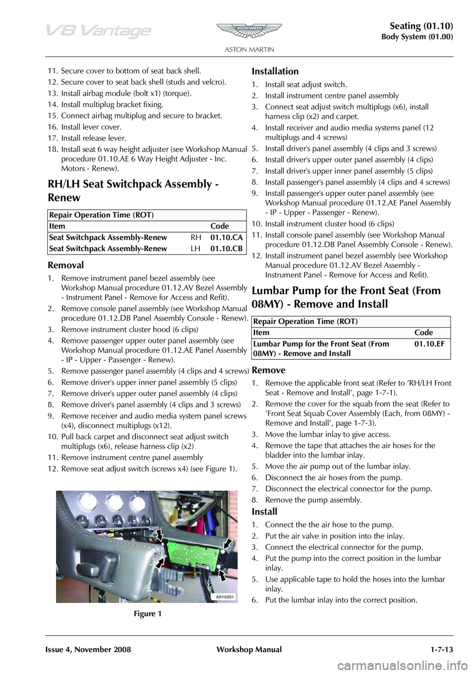
12. Remove seat adjust switch (screws x4) (see Figure 1).
Installation
1. Install seat adjust switch.
2. Install instrument centre panel assembly
3. Connect seat adjust switch multiplugs (x6), install
harness clip (x2) and carpet.
4. Install receiver and audio media systems panel (12 multiplugs and 4 screws)
5. Install driver's panel asse mbly (4 clips and 3 screws)
6. Install driver's upper oute r panel assembly (4 clips)
7. Install driver's upper inne r panel assembly (5 clips)
8. Install passenger's panel assembly (4 clips and 4 screws)
9. Install passenger's upper outer panel assembly (see
Workshop Manual procedure 01.12.AE Panel Assembly
- IP - Upper - Passenger - Renew).
10. Install instrument cluster hood (6 clips)
11. Install console panel assemb ly (see Workshop Manual
procedure 01.12.DB Panel Assembly Console - Renew).
12. Install instrument panel be zel assembly (see Workshop
Manual procedure 01.12.AV Bezel Assembly -
Instrument Panel - Remove for Access and Refit).
Lumbar Pump for the Front Seat (From
08MY) - Remove and Install
Remove
1. Remove the applicable front seat (Refer to ’RH/LH Front Seat - Remove and Install’, page 1-7-1).
2. Remove the cover for the squab from the seat (Refer to ’Front Seat Squab Cover Assembly (Each, from 08MY) -
Remove and Install’, page 1-7-3).
3. Move the lumbar inlay to give access.
4. Remove the tape that attaches the air hoses for the bladder into the lumbar inlay.
5. Move the air pump out of the lumbar inlay.
6. Disconnect the air hoses from the pump.
7. Disconnect the electrical connector for the pump.
8. Remove the pump assembly.
Install
1. Connect the the air hose to the pump.
2. Put the air valve in position into the inlay.
3. Connect the electrical connector for the pump.
4. Put the pump into the correct position in the lumbar inlay.
5. Use applicable tape to hold the hoses into the lumbar inlay.
6. Put the lumbar inlay into the correct position.
Repair Operation Time (ROT)
A0110231
Repair Operation Time (ROT)
Page 80 of 947

Seating (01.10)
Body System (01.00)1-7-14 Workshop Manual Issue 4, November 2008
7. Install the cover for the seat squab (Refer to ’Front Seat Squab Cover Assembly (Each, from 08MY) - Remove
and Install
Page 132 of 947
Wipers and Washer System (01.16)
Body System (01.00)1-11-2 Workshop Manual Issue 4,November, 2008
Specifications
Maintenance
Windscreen Wiper Motor Assembly -
Renew
Removal
1. Remove wiper linkage.
2. Remove arm from motor (nut x1).
3. Remove motor from plate (bolts x3).
Installation
1. Install motor to plate (bolts x3).
2. Ensure wiper motor is in the ‘PARK’ position.
3. Install arm from motor (nut x1), using special tool.
4. Install wiper linkage.
Wiper Linkage Assembly - Renew
Removal
1. Remove brake booster (see Workshop Manual procedure 06.07.DE/06.07.DG Master Cylinder and
Vacuum Booster - Brake - Renew).
2. Remove inlet manifold (see Workshop Manual procedure 03.01.BB/03.01.BF Gasket - Manifold
Assembly - Intake Upper - Renew).
3. Remove wiper arm drivers si de (see Workshop Manual
procedure 01.16.AD Arm Asse mbly - Wiper - Driver -
Renew).
4. Remove wiper arm passengers side (see Workshop Manual procedure 01.16.AE Arm Assembly - Wiper -
Passenger - Renew).
5. Unclip expansion tank hose for access. 6. Remove sound deadening (trim buttons x6).
7. Remove seal from spindle.
8. Remove nuts (x2) from heatshield to move aside.
9. Unclip wiper motor harness (x2) LHS.
10. Unclip windscreen heater harness RHS.
11. Disconnect motor multiplu
g and unclip harness (x2).
12. To prevent damage, protect A/C pipe with tape before
wiper linkage removal.
13. Remove plate securing scre ws (x10) (through plenum).
14. Remove plate securing bolts (x8) (under bonnet).
15. Remove wiper linkage.
Installation
1. Install wiper linkage.
2. Install plate securing bolts (x8) (under bonnet).
3. Install plate securing scre ws (x10) (through scuttle
panel).
4. Connect motor multiplug and clip harness (x2).
5. Clip harness LHS.
6. Clip harness RHS.
7. Refit heatshield and install nuts (x2).
8. Install seal to spindle.
9. Install sound deadening (re-stick, trim buttons x6).
10. Clip expansion tank hose.
11. Install wiper arm drivers side (see Workshop Manual procedure 01.16.AD Arm Assembly - Wiper - Driver -
Renew).
12. Install wiper arm passengers side (see Workshop Manual
procedure 01.16.AE Arm Asse mbly - Wiper - Passenger
- Renew).
13. Install inlet manifold (see Workshop Manual procedure 03.01.BB/03.01.BF Gasket - Manifold Assembly - Intake
Upper - Renew).
14. Install brake booster (see Workshop Manual procedure 06.07.DE/06.07.DG Master Cylinder and Vacuum
Booster - Brake - Renew).
Windshield Wash Tube - Renew
Removal
1. Remove RH wheel arch liner (see Workshop Manual Procedure 01.02.GB Wheel Arch Liner - Front - RH -
Renew).
2. Place container to catch fluid.
Torque Figures
DescriptionTorque Figure (Nm)
Wiper motor crank to motor 35-42Nm
Wiper motor to cowl panel 7-10Nm
Wiper assembly plate 6Nm (M6 Torx) 8Nm (M6 Bolt)
Brake servo nuts 21-24Nm
Brake master cylinder nuts 25
Wiper arm (Driver) 13-17Nm (M8 Nut)
Wiper arm (Passenger) 20-26Nm (M10 Nut) 5-7Nm (M6 Bolt)
Repair Operation Time (ROT)
Repair Operation Time (ROT)
Repair Operation Time (ROT)
ItemCode
Windshield Wash Tube-Renew 01.16.CB