four wheel drive ASTON MARTIN V8 VANTAGE 2010 Workshop Manual
[x] Cancel search | Manufacturer: ASTON MARTIN, Model Year: 2010, Model line: V8 VANTAGE, Model: ASTON MARTIN V8 VANTAGE 2010Pages: 947, PDF Size: 43.21 MB
Page 369 of 947
Engine Sealing (03.10)
Engine (03.00)
Issue 5, Janauary 2010 Workshop Manual 3-10-11
Removal
1. Remove the left side cam cover (Refer to ’Left Side Cam Cover - Remove and Install’, page 3-10-4).
2. Remove the right side cam cover (Refer to ’Right Side Cam Cover - Remove and Install’, page 3-10-9).
Install
1. Install the left side cam cover (Refer to ’Left Side Cam Cover - Remove and Install’, page 3-10-4).
2. Install the right side cam cover (Refer to ’Right Side Cam Cover - Remove and Install’, page 3-10-9).
Engine Timing Cover-Renew (with Engine
Removed
)
Removal
1. Remove the engine assembly (refer Workshop Manual procedure 03.00.AA Engi ne Assembly - Renew).
2. Position drain container.
3. Remove the drain plug and drain the oil from the sump.
4. Remove the left cam cover (Refer to ’Left Side Cam Cover - Remove and Install’, page 3-10-4).
5. Remove the right cam cover (Refer to ’Right Side Cam Cover - Remove and Install’, page 3-10-9).
6. Release the hose clips and disconnect the two coolant hoses from the coolant manifold.
7. Release the hose clip and di sconnect the hose from the
oil separator.
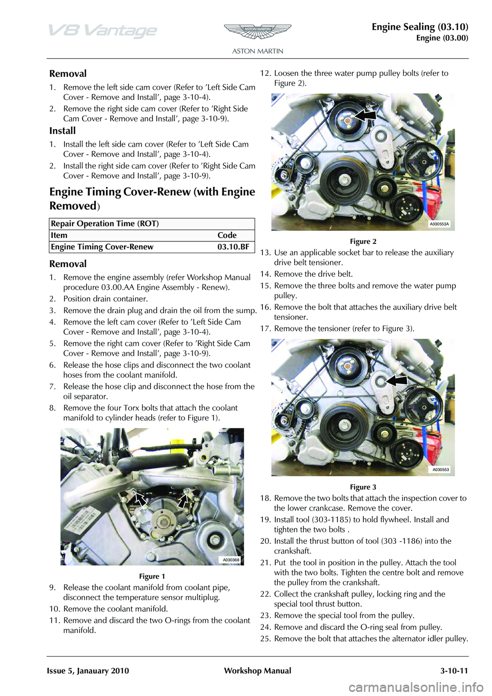
8. Remove the four Torx bolts that attach the coolant manifold to cylinder heads (refer to Figure 1).
Figure 1
9. Release the coolant mani fold from coolant pipe,
disconnect the temperature sensor multiplug.
10. Remove the coolant manifold.
11. Remove and discard the two O-rings from the coolant manifold. 12. Loosen the three water pump pulley bolts (refer to
Figure 2).
Figure 2
13. Use an applicable socket bar to release the auxiliary
drive belt tensioner.
14. Remove the drive belt.
15. Remove the three bolts and remove the water pump pulley.
16. Remove the bolt that attaches the auxiliary drive belt tensioner.
17. Remove the tensioner (refer to Figure 3).
Figure 3
18. Remove the two bolts that attach the inspection cover to the lower crankcase. Remove the cover.
19. Install tool (303-1185) to hold flywheel. Install and tighten the two bolts .
20. Install the thrust button of tool (303 -1186) into the crankshaft.
21. Put the tool in position in the pulley. Attach the tool with the two bolts. Tighten the centre bolt and remove
the pulley from the crankshaft.
22. Collect the crankshaft pulley, locking ring and the special tool thrust button.
23. Remove the special tool from the pulley.
24. Remove and discard the O-ring seal from pulley.
25. Remove the bolt that attaches the alternator idler pulley.
Repair Operation Time (ROT)
A030368
A030553A
A030553
Page 460 of 947
Road Wheels and Tyres (04.04)
Suspension (04.00)4-4-10 Workshop Manual May 2007
Display Unit
The display unit provides additional features when correctly
connected to a previously installed ‘Smartire’ system. The
display unit connects directly to the front of the basic
‘Smartire’ receiver and is powered from the vehicle circuits.
The display will be fully illu minated during use but will go
into ‘Energy Saver’ mode when no activity is detected.
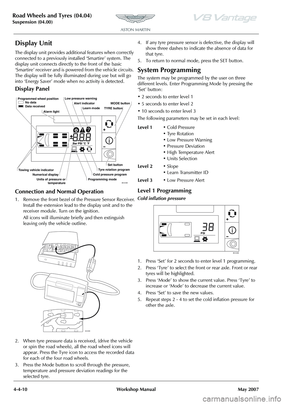
Display Panel
Connection and Normal Operation
1. Remove the front bezel of the Pressure Sensor Receiver. Install the extension lead to the display unit and to the
receiver module. Turn on the ignition.
All icons will illuminate briefly and then extinguish
leaving only the vehicle outline.
2. When tyre pressure data is received, (drive the vehicle
or spin the road wheels), all the road wheel icons will
appear. Press the Tyre icon to access the recorded data
for each of the four road wheels.
3. Press the Mode button to scroll through the pressure, temperature and pressure deviation readings for the
selected tyre. 4. If any tyre pressure sensor is defective, the display will
show three dashes to indicate the absence of data for
that tyre.
5. To return to normal mode, press the SET button.
System Programming
The system may be programmed by the user on three
different levels. Enter Progra mming Mode by pressing the
‘Set’ button:
• 2 seconds to enter level 1
• 5 seconds to enter level 2
• 10 seconds to enter level 3
The following parameters ma y be set in each level:
Level 1 Programming
Cold inflation pressure
1. Press ‘Set’ for 2 seconds to enter level 1 programming .
2. Press ‘Tyre’ to select the front or rear axle. Front or rear
tyres will be highlighted.
3. Press ‘Mode’ to show the current value. Press ‘Tyre’ to increase or ‘Mode’ to decrease the current value.
4. Press ‘Set’ to save the new values.
5. Repeat steps 2 - 4 to set the cold inflation pressure for other the axle.
Programmed wheel position No data
Data received
Alarm light Low pressure warning
Alert indicatorLearn mode MODE button
Set button
Tyre rotation program
Cold pressure program
Programming mode
Towing vehicle indicator
Numerical display
Units of pressure or temperature TYRE button
36-5-038
36-5-039
Level 1
• Cold Pressure
• Tyre Rotation
• Low Pressure Warning
• Pressure Deviation
• High Temperature Alert
•Units Selection
Level 2 •Slope
• Learn Transmitter ID
Level 3 • Low Pressure Alert
PSI
36-5-045
Page 475 of 947
Front Disc Brake (06.03)
Brake Systems (06.00)
Version 6, March 2010 Workshop Manual 6-3-3
Maintenance
Front Brake Disc Set - Renew
Removal
1. Raise the vehicle and make it safe.
2. Remove the road wheels.
3. Remove the pad wear sensors.
4. Remove the dust caps from the bleed nipples.
5. Install a bleed bottle.
6. Loosen the bleed nipples.
7. Push the pistons into calipers and tighten the bleed nipples.
8. Remove the bleed bottle.
9. Install the dust caps on the bleed screws.
10. Remove the brake pad retaining pins and anti-rattle springs.
11. Remove the two caliper attachment bolts from each caliper.
12. Use a cable tie to hold each caliper away.
13. Remove the two disc attachment screws and the two discs.
Installation
1. Clean the two hubs. 2. Install the two discs.
3. Install and torque two attachment screws into each disc.
4. Put each caliper in position and attach it with two new
bolts.
5. Torque the caliper attachment bolts.
6. Clean the calipers, pins, shims and springs.
7. Apply anti-seize compound to the pads, pins and shims.
8. Install the pads and shims into the caliper.
9. Install the pad retaining pins and springs into the calipers.
10. Install the pad wear sensors.
11. Operate the brake pedal four times.
12. Fill the brake fluid reservoir to the correct level.
13. Install the road wheels.
14. Lower the vehicle.
Repair Operation Time (ROT)
WAR NI NG
ALWAYS INSTALL NEW BOLTS WHEN YOU INSTALL THE BRAKE CALIPER. IF YOU DO NOT THE BOLTS
CAN BREAK AND CAUSE FAILURE OF THE BRAKE.
When you install new brake pads, install a new brake pad wear sensor.
WA R N I N G
BEFORE YOU DRIVE THE VEHICLE, OPERATE THE
FOOT BRAKE PEDAL 2 OR 3 TIMES TO MAKE SURE
THAT THE FOOT BRAKE OPERATES CORRECTLY. YOU MUST OPERATE BRAKE CALIPER PISTONS TO CLOSE THE SPACE BETWEEN THE BRAKE PADS AND THE
DISC.
Page 477 of 947
Front Disc Brake (06.03)
Brake Systems (06.00)
Version 6, March 2010 Workshop Manual 6-3-5
14. Install the dust cap for the bleed nipple.
15. Fill the brake fluid reservoir to the correct level.
16. Install road wheel.
17. Lower the vehicle.
Front Pad Kit - Renew
Removal
1. Raise the vehicle and make it safe.
2. Remove the road wheels.
3. Remove the pad wear sensors.
4. Remove the dust caps from the bleed nipples .
5. Install a bleed bottle onto each bleed nipple.
6. Loosen the bleed nipples and push pistons into calipers.
7. Tighten bleed nipples.
8. Remove the bleed bottles.
9. Install the dust caps onto the bleed nipples.
10. Remove the brake pad retaining pins and anti-rattle springs.
11. Remove the pads and shims from the calipers.
Installation
1. Clean the calipers, pins, shims and the springs.
2. Apply anti-seize compound to the pads, pins and shims.
3. Install the pads and shims into the caliper.
4. Install the pad retaining pins and springs into the calipers.
5. Install the pad wear sensors.
6. Operate the brake pedal four times.
7. Fill the brake fluid reservoir to the correct level.
8. Install the road wheels.
9. Lower the vehicle.
Front Brake Hose Assembly - Renew
Removal
1. Raise the vehicle and make it safe.
2. Remove the applicable road wheel.
3. Remove the dust cap from the bleed nipple.
4. Install a bleed bottle onto the applicable caliper.
5. Open the bleed nipple.
6. Push the brake pedal approximately 60 mm and hold it with a support.
7. Tighten the bleed nipple.
8. Remove the bleed bottle.
9. Install the dust cap on the bleed nipple.
10. Disconnect the brake hose union from the caliper.
11. Install sealing plugs in the open ports.
12. Remove the brake pipe union from the hose.
13. Remove the M6 screw that attaches the hose bracket to the body.
14. Remove the hose.
Installation
1. Put the hose in position.
2. Install and torque the M6 screw that attaches the hose bracket to the body.
3. Install and torque the brake pipe union onto the hose.
WA R N I N G
BEFORE YOU DRIVE THE VEHICLE, OPERATE THE
FOOT BRAKE PEDAL 2 OR 3 TIMES TO MAKE SURE
THAT THE FOOT BRAKE OPERATES CORRECTLY. YOU MUST OPERATE BRAKE CALIPER PISTONS TO CLOSE
THE SPACE BETWEEN THE BRAKE PADS AND THE DISC.
Repair Operation Time (ROT)
WA R N I N G
DO NOT USE COMPRESSED AIR TO REMOVE BRAKE
PAD DUST. THE DUST CAN BE DANGEROUS. ALWAYS USE A VACUUM BRUSH OR THE RECOMMENDED BRAKE CLEANER TO REMOVE BRAKE PAD DUST.
When you install new brake pads, install a new brake pad wear sensor.
Repair Operation Time (ROT)
Page 507 of 947
Anti-lock Braking System (ABS) (06.09)
Brake system (06.00)
Issue 4, November 2008 Workshop Manual 6-9-1
Brake system (06.00)
Anti-lock Braking System (ABS) (06.09)
The anti-lock braking system (ABS) is a four-channel system
having independent inputs from all four-wheel speed
sensors.
The ABS module, monitors signals from the sensors to
calculate, brake slip and the acceleration / deceleration of
individual wheels. When the brake pedal is depressed, and
the ABS module detects incipient wheel lock-up from the
incoming signals, it triggers the re-circulation pump inside
the module’s hydraulic modulator, and the solenoid valves
for the wheel(s) concerned. Brake pressure, is then
modulated to increase / decrease or remain constant at the
wheel(s) concerned until whee l lock-up is eliminated. The
ABS provides self-diagnosis and any malfunction within the
system will be indicated to the dr iver by the illumination of
the brake warning light and ‘ABS FAULT’ displayed in the
message centre right. Should a fault develop within the ABS,
the brake system will operate conventionally and with the
same standard of performanc e as a vehicle not equipped
with ABS.
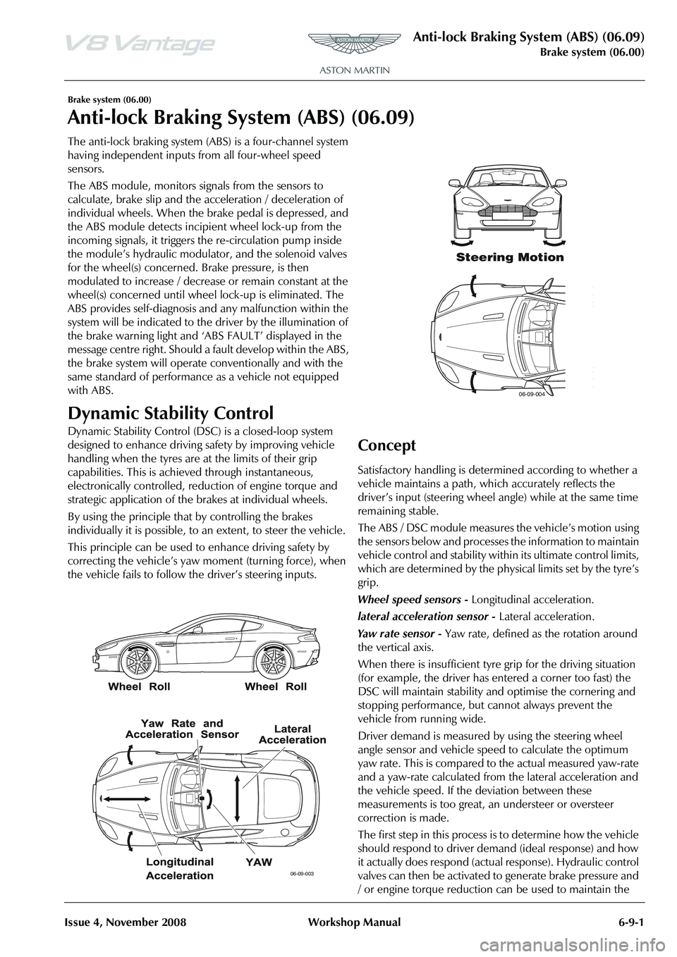
Dynamic Stability Control
Dynamic Stability Control (DSC ) is a closed-loop system
designed to enhance driving safety by improving vehicle
handling when the tyres are at the limits of their grip
capabilities. This is achieved through instantaneous,
electronically controlled, reduction of engine torque and
strategic application of the brakes at individual wheels.
By using the principle that by controlling the brakes
individually it is possible, to an extent, to steer the vehicle.
This principle can be used to enhance driving safety by
correcting the vehicle’s yaw moment (turning force), when
the vehicle fails to follow th e driver’s steering inputs.
Concept
Satisfactory handling is determined according to whether a
vehicle maintains a path, wh ich accurately reflects the
driver
Page 617 of 947
Steering Column (11.04)
Steering (11.00)11-4-2 Workshop Manual Issue 4, November 2008
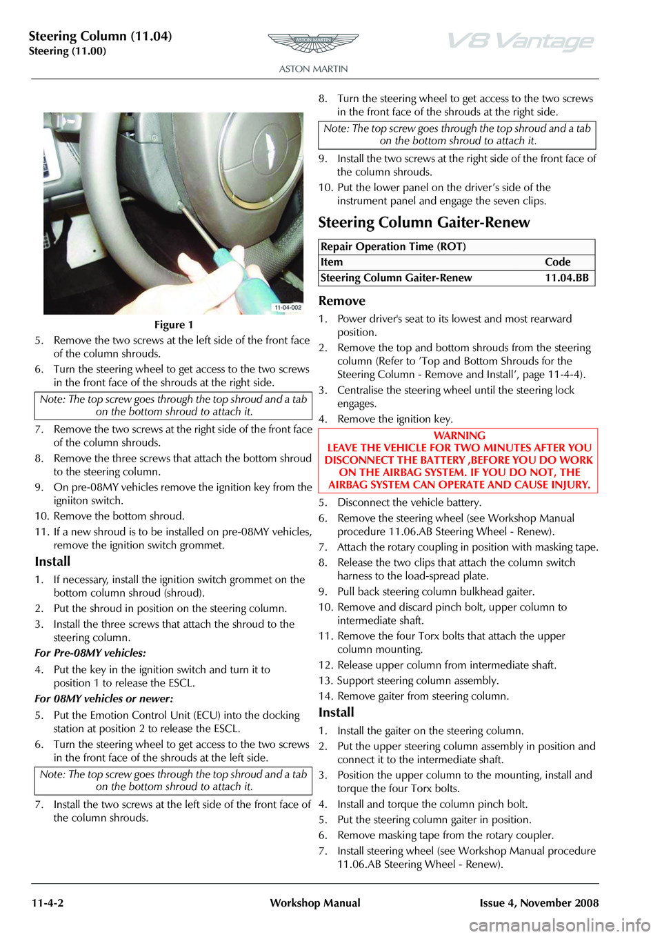
5. Remove the two screws at the left side of the front face of the column shrouds.
6. Turn the steering wheel to get access to the two screws in the front face of the shrouds at the right side.
7. Remove the two screws at the right side of the front face of the column shrouds.
8. Remove the three screws that attach the bottom shroud to the steering column.
9. On pre-08MY vehicles remove the ignition key from the igniiton switch.
10. Remove the bottom shroud.
11. If a new shroud is to be installed on pre-08MY vehicles, remove the ignition switch grommet.
Install
1. If necessary, install the ignition switch grommet on the bottom column shroud (shroud).
2. Put the shroud in position on the steering column.
3. Install the three screws that attach the shroud to the steering column.
For Pre-08MY vehicles:
4. Put the key in the ignition switch and turn it to position 1 to release the ESCL.
For 08MY vehicles or newer:
5. Put the Emotion Control Unit (ECU) into the docking station at position 2 to release the ESCL.
6. Turn the steering wheel to get access to the two screws in the front face of the shrouds at the left side.
7. Install the two screws at the left side of the front face of the column shrouds. 8. Turn the steering wheel to get access to the two screws
in the front face of the shrouds at the right side.
9. Install the two screws at the right side of the front face of the column shrouds.
10. Put the lower panel on the driver’s side of the instrument panel and engage the seven clips.
Steering Column Gaiter-Renew
Remove
1. Power driver's seat to its lowest and most rearward position.
2. Remove the top and bottom shrouds from the steering column (Refer to ’Top and Bottom Shrouds for the
Steering Column - Remove and Install’, page 11-4-4).
3. Centralise the steering whee l until the steering lock
engages.
4. Remove the ignition key.
5. Disconnect the vehicle battery.
6. Remove the steering wheel (see Workshop Manual procedure 11.06.AB Steering Wheel - Renew).
7. Attach the rotary coupling in position with masking tape.
8. Release the two clips that attach the column switch harness to the load-spread plate.
9. Pull back steering column bulkhead gaiter.
10. Remove and discard pinch bolt, upper column to intermediate shaft.
11. Remove the four Torx bolts that attach the upper column mounting.
12. Release upper column from intermediate shaft.
13. Support steering column assembly.
14. Remove gaiter from steering column.
Install
1. Install the gaiter on the steering column.
2. Put the upper steering column assembly in position and connect it to the intermediate shaft.
3. Position the upper column to the mounting, install and torque the four Torx bolts.
4. Install and torque the column pinch bolt.
5. Put the steering column gaiter in position.
6. Remove masking tape from the rotary coupler.
7. Install steering wheel (see Workshop Manual procedure 11.06.AB Steering Wheel - Renew).
Figure 1
Note: The top screw goes thro ugh the top shroud and a tab
on the bottom shroud to attach it.
Note: The top screw goes thro ugh the top shroud and a tab
on the bottom shroud to attach it.
Note: The top screw goes thro ugh the top shroud and a tab
on the bottom shroud to attach it.
Repair Operation Time (ROT)
ItemCode
Steering Column Gaiter-Renew 11.04.BB
WAR NI NG
LEAVE THE VEHICLE FOR TWO MINUTES AFTER YOU
DISCONNECT THE BATTERY ,BEFORE YOU DO WORK ON THE AIRBAG SYSTEM. IF YOU DO NOT, THE
AIRBAG SYSTEM CAN OPERATE AND CAUSE INJURY.
Page 618 of 947

Steering Column (11.04)
Steering (11.00)
Issue 4, November 2008 Workshop Manual 11-4-3
8. Connect vehicle battery.
9. Install the steering column shrouds (Refer to ’Top and Bottom Shrouds for the Steering Column - Remove and
Install’, page 11-4-4).
10. Put the driver’s seat and the steering column in their initial positions.
Upper Steering Column Assembly-
Renew
Remove
1. Power driver's seat to it s lowest and most rearward
position.
2. Remove the top and bottom shrouds from the steering column (Refer to ’Top and Bottom Shrouds for the
Steering Column - Remove and Install’, page 11-4-4).
3. Disconnect vehicle battery.
4. Centralise the steering whee l until the steering lock
engages.
5. Remove the ignition key.
6. Disconnect the battery.
7. Remove the steering wheel (Refer to ’Steering Wheel- Renew’, page 11-6-1).
8. Attach the rotary coupling in position with masking tape.
9. Disconnect steering column switch multiplugs (x5).
10. Remove screw securing load-spread plate to column and collect column shrouds mounting bracket.
11. Release clips (x2) from column switch harness to load- spread plate.
12. Pull back steering co lumn bulkhead gaiter. 13. Remove and discard pinch bolt from upper column to
intermediate shaft.Figure 1
14. Remove the four Torx screws from the upper column mounting.
15. Release upper column from intermediate shaft.
16. Disconnect multiplug from steering sensor and remove
steering column assembly.
17. Unclip steering column sw itches from column and
remove switch gear.
18. Mark fitted position of rotary coupler and remove rotary coupler.
19. Remove gaiter from steering column.
20. Remove Torx screws (x3) from securing steering sensor to mounting bracket.
21. Remove sensor.
22. Remove Torx screws (x3) that secure steering sensor mounting bracket to column and remove bracket.
Install
1. Position steering sensor mounting bracket, install and tighten Torx screws (x3).
2. Install the steering sensor, install and tighten Torx screws (x3).
3. Install gaiter on steering column.
4. Install steering column switch gear and secure clips.
5. Install the rotary coupler to marked position and secure
with masking tape.
6. Position upper steering column assembly and connect to intermediate shaft.
7. Connect multiplug to steering sensor.
8. Position upper column to mounting bracket, install and torque tighten Torx bolts (x4).
9. Install and torque tighten column pinch bolt.
10. Connect multiplugs (x5).
11. Position load-spread plate and secure harness clips (x2).
12. Install load-spread plate and secure with screw.
Repair Operation Time (ROT)
Page 620 of 947

Steering Column (11.04)
Steering (11.00)
Issue 4, November 2008 Workshop Manual 11-4-5
Steering Column Lower Shaft Assembly-
Renew
Remove
1. Operate the driver's seat to its lowest and most rearward position.
2. Raise the vehicle and make it safe.
3. Remove the left side front wheel arch liner (see Workshop Manual procedure 01.02.FB Wheel Arch
Liner - Front - LH - Renew).
4. Remove and discard the link bolt that attaches the lower steering column shaft to the coupling.
5. Release the shaft link for the lower steering column from the coupling.
6. Lower the vehicle.
7. Remove the top and bottom shrouds from the steering column (Refer to ’Top and Bottom Shrouds for the
Steering Column - Remove and Install’, page 11-4-4).
8. Disconnect the vehicle battery.
9. Turn the steering to the centre posiiton to engage the column lock and remove the ignition key.
10. Remove the steering wheel (Refer to ’Steering Wheel-
Renew’, page 11-6-1).
11. Use masking tape to hold the rotary coupling in position.
12. Release the two clips that attach the column switch
harness to the load-spread plate.
13. Pull back the steering column bulkhead gaiter.
14. Remove and discard the pinch bolt that attaches the upper column to the intermediate shaft.
15. Remove the four Torx bolts that attach the upper column mounting.
16. Release the upper column from lower steering column shaft.
17. Use an applicable support to hold the steering column assembly.
18. Remove the lower steering column shaft.
Installation
1. Install the lower steering column shaft.
2. Raise the vehicle and make it safe.
3. Connect the lower steering shaft to the coupling.
4. Install a new bolt but do not torque at this stage.
5. Lower the vehicle.
6. Put the upper steering column assembly in posiiton.
7. Connect it to the intermediate shaft.
8. Put the upper column in position on its mounting.
9. Install and torque the four Torx bolts.
10. Install and torque column pinch bolt. 11. Put the steering column gaiter in position.
12. Remove the masking tape
from the rotary coupler.
13. Install steering wheel (Refer to ’Steering Wheel-Renew’, page 11-6-1).
14. Install the steering column shrouds (Refer to ’Top and Bottom Shrouds for the Steering Column - Remove and
Install’, page 11-4-4).
15. Raise the vehicle and make it safe.
16. Torque tighten lower steering column shaft link bolt.
17. Install LH front wheel arch liner (see Workshop Manual procedure 01.02.FB Wheel Arch Liner - Front - LH -
Renew).
18. Lower the vehicle.
19. Connect the vehicle battery.
20. Put the driver’s seat and the steering column in their
initial positions.
Repair Operation Time (ROT)
Caution
Align the steering wheel and the rack to the centre position during assembly. If you do not, the rotary
coupling can be damaged. Also, it can be difficult to
align the steering wheel in the straight-ahead position.