Timing ASTON MARTIN V8 VANTAGE 2010 Workshop Manual
[x] Cancel search | Manufacturer: ASTON MARTIN, Model Year: 2010, Model line: V8 VANTAGE, Model: ASTON MARTIN V8 VANTAGE 2010Pages: 947, PDF Size: 43.21 MB
Page 234 of 947

3-0-2 Workshop Manual Issue 5, January 2010
Drive Belt-Renew ...................................................5-1
Engine Drive Belt and Bracket Assembly Oil Pump
Tensioner-Renew ...................................................5-1
Idler Pulley-Renew .................................................5-2
Engine Drive Belt Idler Assembly-Renew ................5-2
Engine Cranking System (03.06) ........................... 3-6-1 Maintenance ...........................................................6-1 Starter Motor-Renew ..............................................6-1
Ignition System (03.07) ......................................... 3-7-1 Maintenance ...........................................................7-1 Coil Assembly-Engine Set - LH-Renew ....................7-1
Emission Control (03.08) ...................................... 3-8-1 Maintenance ...........................................................8-1 Vacuum Outlet Hose Assemb ly-Renew ..................8-1
Secondary Air Injection Pump Tube-Renew............8-1
Vacuum System Reservoir and Bracket Assembly
- Renew .................................................................8-1
Oil Tank Breather Hose-Renew ..............................8-1
Air Cleaner to Rocker Cover Hose-Renew ..............8-1
Oil Separator Tube Assembly-Renew ......................8-1
Oil Separator Assembly-Renew...............................8-2
Emissions Separator Hose-Renew ...........................8-2
Secondary Air Injection Pump and Bracket
Assembly-Renew ....................................................8-2
PCV Valve Assembly-Renew ...................................8-2
Crank Vent Hose-Renew ........................................8-3
Exhaust Valve to Exhaust Manifold Tube Assembly
- Renew .................................................................8-3
Oil Separator to Inlet Manifold Hose- Renew .........8-3
EGR Module-Renew...............................................8-3
Valve Train (03.09)................................................ 3-9-1 Specifications ..........................................................9-1
Maintenance ...........................................................9-1 Left Side Timing Chain Arm Assembly - Remove
and Install ..............................................................9-1
Right Side Timing Chain Arm Assembly - Remove
and Install ..............................................................9-8
RH/LH Secondary Tensioner Assembly - Remove
and Install ............................................................9-14
Right and Left Intake Camshaft - Remove
and Install ............................................................9-15
Right and Left Exhaust Camshaft - Remove
and Install ............................................................9-17
RH/LH Secondary Timing Chain-Renew ...............9-18
RH/LH Secondary Tensioner Assembly-Renew
(with Engine Removed).........................................9-19
RH/LH Intake Camshaft Renew With Engine
Removed .............................................................9-20
RH/LH Exhaust Camshaft-Renew (with Engine
Removed) ............................................................9-22
RH/LH Secondary Timing Chain-Renew (with
Engine Removed) .................................................9-24
RH/LH Intake Camshaft Sprocket and Housing Assembly-
Renew......................................................................9-25 Left Side Primary Chain - Re move and Install).......9-26
RH/LH Intake Camshaft Sprocket and Housing
Assembly-Renew (with Engine Removed) .............9-29
Engine Sealing (03.10) ........................................ 3-10-1 Specifications ........................................................10-1 Maintenance ......................................................... 10-1
Engine Timing Cover - Renew .............................. 10-1
Left Side Cam Cover - Remove and Install ............ 10-4
Left Side Cam Cover Gasket - Renew ................... 10-5
Right Side Cam Cover Gasket - Renew ................. 10-6
Cylinder Head Gasket - Renew (Engine Set) ......... 10-6
Right Side Cam Cover - Remove and Install .......... 10-9
Cam Cover - Vehicle Set - Remove and Install .... 10-10
Engine Timing Cover- Renew (with Engine
Removed) .......................................................... 10-11
John Guest Cartridge in the Engine Timing Cover
- Repair .............................................................. 10-14
Power Conversion (03.11) ...................................3-11-1 Maintenance ......................................................... 11-1 Connecting Rod Bearing-Renew (Engine Set) ........ 11-1
Crankshaft Main Bearing-Renew (Engine Set)........ 11-1
Crankshaft Assembly-Renew................................. 11-4
Piston-Renew (Engine Set) .................................... 11-7
Piston-Renew ..................................................... 11-12
Additional Piston-Renew (E ach) .......................... 11-17
Piston Ring-Renew (Engine Set) .......................... 11-18
Piston Ring-One Piston Se t-Renew ..................... 11-23
Piston Ring Set-Additional -Renew (Each) ............ 11-28
Connecting Rod-Renew (Engin e Set) .................. 11-29
Crankshaft Damper Pulley Assembly-Renew ....... 11-34
Crankshaft Front Oil Seal-R enew ........................ 11-35
Rear Oil Crankshaft Seal-Renew ......................... 11-36
Cylinder Block-Renew........................................ 11-36
Crankshaft Damper Pulley Assembly-Renew
(with Engine Removed) ...................................... 11-37
Crankshaft Front Oil Seal-Renew (with
Engine Removed) ............................................... 11-37
Crankshaft Rear Oil Seal-Renew (with
Engine Removed) ............................................... 11-38
Air Charging (03.12) .......... ..................................3-12-1
Maintenance ......................................................... 12-1 Clean Air Duct - Remove and Install ..................... 12-1
Engine Air Filter - Remove and Install ................... 12-1
Engine Air Cleaner Assembly - Remove
and Install ............................................................ 12-2
Evaporative Emissions (03.13 ) .............................3-13-1
Description ........................................................... 13-1 System Operation ................................................ 13-1
Engine Management System (03.14) ...................3-14-1 Maintenance ......................................................... 14-1 Right Engine Control Module - Renew.................. 14-1
LH Front Lower Heated Exhaust Gas Oxygen
(HEGO) Sensor - Renew....................................... 14-1
LH Front Upper Heated Exhaust Gas Oxygen
(HEGO) Sensor - Renew....................................... 14-1
RH Front Upper Heated Exhaust Gas Oxygen
(HEGO) Sensor - Renew....................................... 14-2
RH Rear Lower Heated Exhaust Gas Oxygen
(HEGO) Sensor - Renew....................................... 14-2
Left Side Powertrain Control Module (PCM)
(Coupe Only) - Remove and Install....................... 14-3
Left Side Powertrain Control Module (PCM)
(Roadster Only) - Remove and Install.................... 14-4
Page 236 of 947
Engine Assembly (03.00)
Engine (03.00)3-0-4 Workshop Manual Issue 5, January 2010
Engine (03.00)
Engine Assembly (03.00)
Description
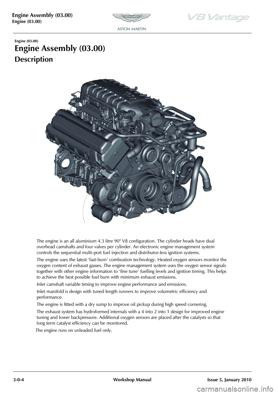
The engine is an all aluminium 4.3 litre 90° V8 configuration. The cylinder heads have dual
overhead camshafts and four valves per cylinder. An electronic engine management system
controls the sequential multi-port fuel injection and distributor-less ignition systems.
The engine uses the latest ‘fast-burn’ combustion technology. Heated oxygen sensors monitor the
oxygen content of exhaust gasses . The engine management system uses the oxygen sensor signals
together with other engine information to ‘fine tune ’ fuelling levels and ignition timing. This helps
to achieve the best possible fuel bur n with minimum exhaust emissions.
Inlet camshaft variable timing to impr ove engine performance and emissions.
Inlet manifold is design with tuned length runners to improve volumetric efficiency and
performance.
The engine is fitted with a dry sump to improv e oil pickup during high speed cornering.
The exhaust system has hydroforme d internals with a 4 into 2 into 1 design for improved engine
tuning and lower backpressure. Additional oxygen sensors are placed after the catalysts so that
long term catalyst efficiency can be monitored.
The engine runs on unleaded fuel only.
Page 260 of 947

Engine Structure (03.01)
3-1-12Workshop ManualIssue 4, November 2008
6. Install new gasket on exhaust manifold.
7. Install EGR pipe to exhaust manifold and EGR valve.,
8. Install EGR pipe to EGR valve, install pipe union. Do not
torque tighten at this stage.
9. Install and torque tighten bolts (x2), EGR pipe to exhaust manifold. Torque tighten pipe union.
10. Connect EGR vacuum hose.
11. Connect throttle body multiplug and harness clip.
12. Connect manifold heating hoses (x2).
13. Connect EGR vacuum pipe to sensor and manifold.
14. Install coolant pipe bracket, install and torque tighten bolts (x2) and nuts (x2).
15. Connect multiplugs to EGR valve, fuel rail pressure
sensor and injectors.
16. Install alternator and injector harness fir tree clips (x3) to coolant pipe bracket.
17. Install heater hose clips (x2) and EGR vacuum lines clips (x2) to bracket.
18. Install harness bracket to engine.
19. Refit harness fir tree clips to cylinder head.
20. Refit engine breather hose.
21. Install VVT solenoid multiplug, position coil and CMP harness (1x edge clip).
22. Install coil cover.
23. Connect breather hose to manifold (quickfit).
24. Connect IAT multiplug.
25. Secure injector harness clips (x2) to LH engine cover.
26. Connect injector multiplugs (x4).
27. Install pipe support bracket, install and tighten nuts (x2
and bolts(x2).
28. Install harness support bracket, install and tighten bolt (x1) and, nut (x1).
29. Install heater hoses (x2) an d throttle body hoses (x2) in
support bracket.
30. Connect breather hoses (x2) to engine cover.
31. Install coil cover.
RH/LH Cylinder Head Gasket - Renew
Removal
1. Re-install front subframe to body, install and tighten bolts (x6), remove support trolley.
2. Install and tighten engine mounting nuts (x2).
3. With assistance, remove engine lifting beam (SPX M553D). 4. Remove SAI pump and bracket assembly (see Workshop
Manual procedure 03.08.DB/03.08.DJ Pump and
Bracket Assembly - Secondary Air Injection - Renew).
5. Disconnect multiplugs (x2) from knock sensors.
6. Disconnect multiplug from camshaft timing sensor.
7. Remove RH/LH exhaust manifold (see Workshop Manual procedure 09.00.CC/09.00.CD Gasket -
Exhaust Manifold - RH/LH - Renew).
8. Remove RH/LH intake camshaft (see Workshop Manual procedure 03.09.AT/03.09.AV Camshaft - Intake - RH/
LH - Renew).
9. Remove RH exhaust camshaft bearing cap retaining bolts (x10) evenly and in stages (see Figure 1).
Figure 1
10. Note their orientation and markings and remove the RH
exhaust camshaft bearing caps.
11. Remove RH exhaust camshaft (see Figure 2).
12. Remove bolts (x2) securing front end of RH cylinder
head to cylinder block.
Repair Operation Time (ROT)
Figure 2
A0309258
A0309260
Page 261 of 947
Engine Structure (03.01)
Issue 4, November 2008Workshop Manual 3-1-13
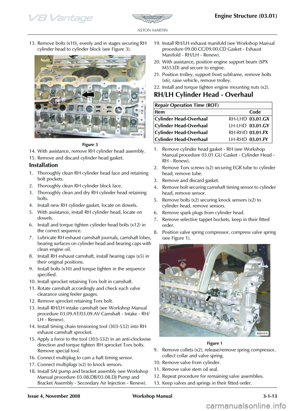
13. Remove bolts (x10), evenly and in stages securing RH
cylinder head to cylinder block (see Figure 3).
Figure 3
14. With assistance, remove RH cylinder head assembly.
15. Remove and discard cylinder head gasket.
Installation
1. Thoroughly clean RH cylind er head face and retaining
bolt pockets.
2. Thoroughly clean RH cylinder block face.
3. Thoroughly clean and dry RH cylinder head retaining
bolts.
4. Install new RH cylinder gasket, locate on dowels.
5. With assistance, install RH cylinder head, locate on dowels.
6. Install and torque tighten cylinder head bolts (x12) in the correct sequence.
7. Lubricate RH exhaust camsha ft journals, camshaft lobes,
bearing surfaces on cylinder head and bearing caps with
clean engine oil.
8. Install RH exhaust camshaft, install bearing caps (x5) in their original positions.
9. Install bolts (x10) and torque tighten in the sequence specified.
10. Install sprocket retaining Torx bolt in camshaft.
11. Rotate camshaft accordingly and check each valve clearance using feeler gauges.
12. Remove sprocket retaining Torx bolt.
13. Install RH/LH intake cams haft (see Workshop Manual
procedure 03.09.AT/03.09.AV Camshaft - Intake - RH/
LH - Renew).
14. Install timing chain tensioni ng tool (303-532) into RH
exhaust camshaft sprocket.
15. Apply a force to the tool (303-532) in an anti-clockwise direction and torque tighten RH sprocket Torx bolts.
Remove special tool.
16. Connect multiplug to cam a haft timing sensor.
17. Connect multiplugs (x2) to knock sensors.
18. Install SAI pump and bracket assembly (see Workshop Manual procedure 03.08.DB/03.08.DJ Pump and
Bracket Assembly - Secondary Air Injection - Renew). 19. Install RH/LH exhaust manifold (see Workshop Manual
procedure 09.00.CC/09.00.CD Gasket - Exhaust
Manifold - RH/LH - Renew).
20. With assistance, position engine support beam (SPX M553D) and secure to engine.
21. Position trolley, support front subframe, remove bolts (x6), raise vehicle, remove trolley.
22. Install and torque tighten engine mounting nuts (x2).
RH/LH Cylinder Head - Overhaul
1. Remove cylinder head gasket - RH (see Workshop Manual procedure 03.01.GU Gasket - Cylinder Head -
RH - Renew).
2. Remove Torx screws (x2) se curing EGR tube to cylinder
head, remove tube.
3. Remove and discard gasket.
4. Remove bolt securing camshaf t timing sensor to cylinder
head, remove sensor.
5. Remove bolts (x2) securing knock sensors (x2) to cylinder head, remove sensors.
6. Remove spark plugs from cylinder head.
7. Remove selective tappet buckets, keep in their fitted order.
8. Position valve spring compressor, compress valve spring (see Figure 1).
Figure 1
9. Remove collets (x2), releas e/remove spring compressor,
collect collar and valve spring.
10. Remove valve from cylinder.
11. Remove valve stem oil seal.
12. Repeat procedure for remaining valve assemblies.
13. Keep valves and springs in their fitted order.
A0310319
Repair Operation Time (ROT)
A0301310
Page 262 of 947
Engine Structure (03.01)
3-1-14Workshop ManualIssue 4, November 2008
14. Inspect cylinder head face for warpage, across centre
and from corner to corner.
15. Check condition and measure free length of valve springs.
16. Decarbonise combustion chambers and exhaust ports.
17. Measure valve stem diameters.
18. Use new valves and check valve guide clearance.
Installation
1. Clean cylinder head face and inlet/exhaust manifold faces. Use and air line to completely dry cylinder head
surfaces.
2. Lubricate and install intake and exhaust valves (x16).
3. Install valve stem oil seals.
4. Install valve springs and collars.
5. Using valve spring compressor, compress valve spring, install collets.
6. Release/remove spring compressor.
7. Repeat procedure for remaining valve assemblies.
8. Install selective tappet buckets in their original fitted positions.
9. Lubricate intake camshaft bearings and journals with clean engine oil.
10. Install intake camshaft, install bearing caps (x5), install bolts (x10).
11. Torque tighten bearing cap bolts in the correct sequence.
12. Lubricate exhaust camshaft be arings and journals with
clean engine oil.
13. Install exhaust camshaft, install bearing caps (x5), install bolts (x10).
14. Torque tighten bearing cap bolts in the correct sequence.
15. Install camshaft sprocket Torx bolts in intake and exhaust camshafts.
16. Rotate intake camshaft clockwise, check and log each valve clearance using feeler gauges.
17. Calculate the correct tappet bucket grade.
18. Repeat procedure for exhaust valve clearances.
19. Remove bearing cap bolts (x10), remove bearing caps (x5), remove intake camshaft.
20. Remove tappet buckets, install selected tappet buckets.
21. Repeat procedure for exhaust valve clearances.
22. Install intake camshaft, install bearing caps (x5), install bolts (x10).
23. Torque tighten bearing cap bolts in the correct sequence.
24. Rotate intake camshaft clockwise, re-check each valve clearance using feeler gauges.
25. Repeat procedure and re-check exhaust valve clearances.
26. Remove camshaft sprocket Torx bolts (x2).
27. Remove bearing cap bolts (x10), remove bearing caps (x5), remove intake camshaft. 28. Remove bearing cap bolts (x10), remove bearing caps
(x5), remove exhaust camshaft.
29. Clean EGR tube.
30. Install new gasket, install EGR tube to cylinder head, install and torque tighten Torx screws (x2).
31. Clean Knock sensors (x2).
32. Install knock sensors (x2) to cylinder head, install and torque tighten bolts (x2).
33. Clean camshaft timing sensor.
34. Install camshaft timing sensor, install and torque tighten bolt.
35. Install spark plugs.
36. Install cylinder head gasket RH (see Workshop Manual procedure 03.01.GU Gasket - Cylinder Head - RH -
Renew).
Cylinder Head (Engine Set) - Overhaul
Removal
1. Remove cylinder head gaskets - engine set (see Workshop Manual procedure 03.10.AL Gasket -
Cylinder Head - Engine Set - Renew).
2. Remove Torx screws (x4) securing EGR tubes to cylinder heads, remove tubes.
3. Remove and discard gaskets.
4. Remove bolts (x2) securing camshaft timing sensors to cylinder heads, remove sensors.
5. Remove bolts (x4) securing knock sensors (x4) to cylinder heads, remove sensors.
6. Remove spark plugs from cylinder heads (x8).
7. Remove selective tappet buckets, keep in their fitted order.
8. Position valve spring compressor, compress valve springs.
9. Remove collets, release/remove spring compressor, collect collars and valve springs.
10. Remove valves from cylinder heads.
11. Remove valve stem oil seals.
12. Keep valves and springs in their fitted order.
13. Inspect cylinder head face for warpage, across centre and from corner to corner.
14. Check condition and measure free length of valve springs.
15. Decarbonise combustion chambers and exhaust ports.
16. Use new valves and check valve guide clearances.
Installation
1. Clean cylinder head face and inlet/exhaust manifold faces. Use and air line to completely dry cylinder head
surfaces.
Repair Operation Time (ROT)
ItemCode
Cylinder Head (Engine Set)-Overhaul LHD03.01.GZ
Cylinder Head (Engine Set)-Overhaul RHD03.01.FZ
Page 263 of 947
Engine Structure (03.01)
Issue 4, November 2008Workshop Manual 3-1-15
2. Lubricate and install intake and exhaust valves (x16).
3. Install valve stem oil seals.
4. Install valve springs and collars.
5. Using valve spring compressor, compress valve spring,
install collets.
6. Release/remove spring compressor.
7. Install selective tappet buckets in their original fitted positions.
8. Lubricate intake and exha ust camshaft bearings and
journals with clean engine oil.
9. Install intake and exhaust camshafts, install bearing caps (x20), install bolts (x40).
10. Torque tighten bearing cap bolts in the correct sequence.
11. Install camshaft sprocket Torx bolts in intake and exhaust camshafts.
12. Rotate intake camshaft cl ockwise, check and log each
valve clearance using feeler gauges.
13. Calculate the correct tappet bucket grade.
14. Remove bearing cap bolts (x40), remove bearing caps
(x20), remove intake and exhaust camshafts.
15. Remove tappet buckets, install selected tappet buckets.
16. Install intake and exhaust camshafts, install bearing caps (x20), install bolts (x40).
17. Torque tighten bearing cap bolts in the correct sequence.
18. Rotate intake and exhaus t camshafts clockwise, re-
check each valve clearance using feeler gauges.
19. Remove camshaft sprocket Torx bolts (x4).
20. Remove bearing cap bolts (x40), remove bearing caps
(x20), remove intake and exhaust camshafts.
21. Clean EGR tubes.
22. Install new gaskets, install EGR tubes to cylinder heads, install and torque tighten Torx screws (x4).
23. Clean Knock sensors (x4).
24. Install knock sensors (x4) to cylinder head, install and torque tighten bolts (x4).
25. Clean camshaft timing sensors.
26. Install camshaft timing sensor, install and torque tighten bolt.
27. Install spark plugs.
28. Install cylinder head gaskets - engine set (see Workshop Manual procedure 03.10.AL Gasket - Cylinder Head -
Engine Set - Renew).
Valve Set (Engine Set) - Renew (including
de-coke)
Removal
1. Remove cylinder head gaskets - engine set (see Workshop Manual procedure 03.10.AL Gasket -
Cylinder Head - Engine Set - Renew).
2. Remove spark plugs (x8).
3. Remove selective tappet buckets, keep in their fitted order.
4. Position valve spring compressor, compress valve spring.
5. Remove collets, release/remove spring compressor, collect collar and valve spring.
6. Remove valves from cylinder.
7. Remove valve stem oil seals.
8. Keep valves and springs in their fitted order.
9. Inspect cylinder head face for warpage, across centre and from corner to corner.
10. Check condition and measure free length of valve springs.
11. Decarbonise combustion chambers and exhaust ports.
12. Use new valves and check valve guide clearances.
Installation
1. Clean cylinder head face and inlet/exhaust manifold faces. Use and air line to completely dry cylinder head
surfaces.
2. Lubricate and install intake and exhaust valves (x32).
3. Install valve stem oil seals.
4. Install valve springs and collars.
5. Using valve spring compressor, compress valve spring, install collets.
6. Release/remove spring compressor.
7. Install selective tappet buckets in their original fitted positions.
8. Lubricate intake and exhaust camshaft bearings and journals with clean engine oil.
9. Install intake and exhaust camshafts, install bearing caps (x20), install bolts (x40).
10. Torque tighten bearing cap bolts in the correct sequence.
11. Install camshaft sprocket Torx bolts in intake and exhaust camshafts.
12. Rotate intake camshaft clockwise, check and log each valve clearance using feeler gauges.
13. Calculate the correct tappet bucket grade.
14. Remove bearing cap bolts (x40), remove bearing caps (x20), remove intake and exhaust camshafts.
15. Remove tappet buckets, install selected tappet buckets.
16. Install intake and exhaust camshafts, install bearing caps (x20), install bolts (x40).
17. Torque tighten bearing cap bolts in the correct sequence.
18. Rotate intake and exhaust camshafts clockwise, re- check each valve clearance using feeler gauges.
19. Remove camshaft sprock et Torx bolts (x4).
Repair Operation Time (ROT)
Page 268 of 947
Engine Structure (03.01)
3-1-20Workshop ManualIssue 4, November 2008
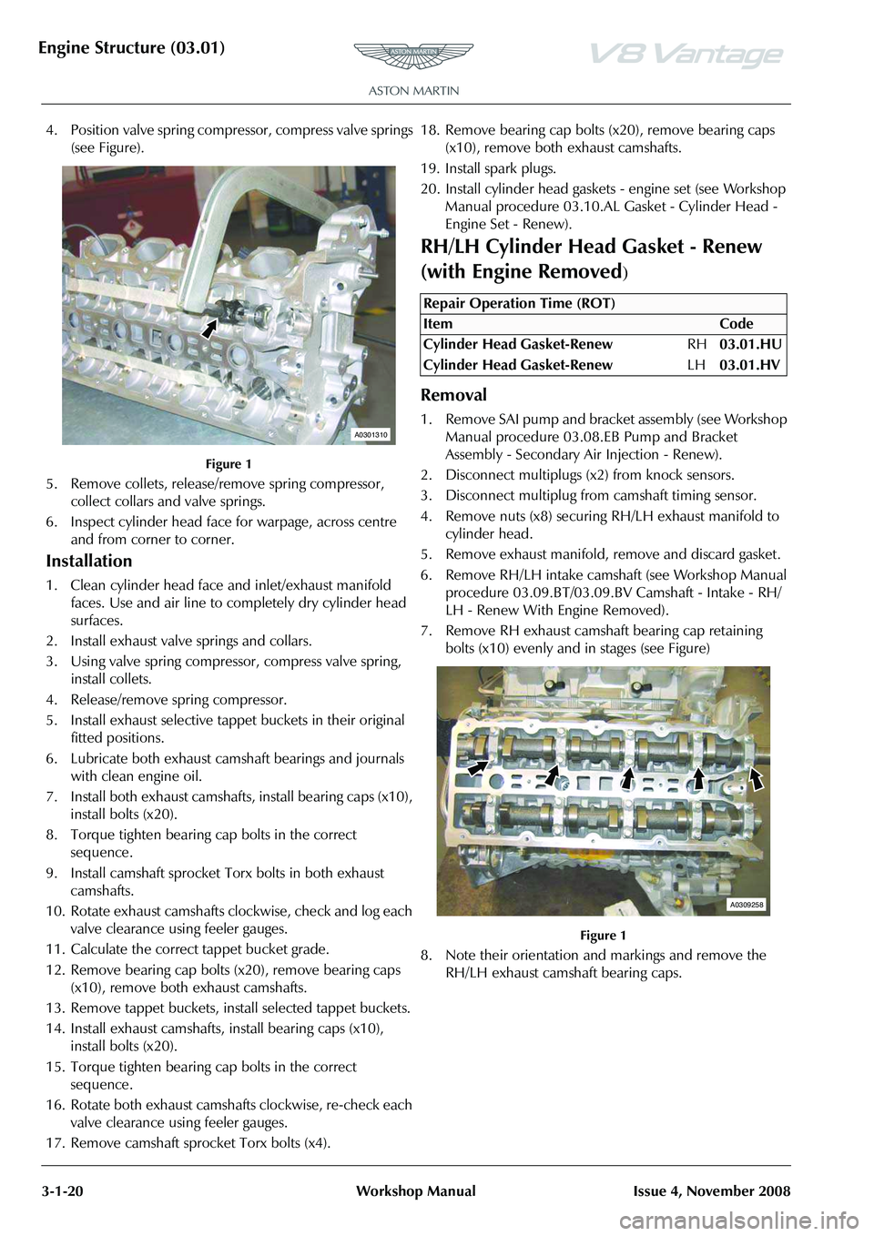
4. Position valve spring compressor, compress valve springs
(see Figure).
Figure 1
5. Remove collets, release/re move spring compressor,
collect collars and valve springs.
6. Inspect cylinder head face for warpage, across centre and from corner to corner.
Installation
1. Clean cylinder head face and inlet/exhaust manifold faces. Use and air line to completely dry cylinder head
surfaces.
2. Install exhaust valve springs and collars.
3. Using valve spring compressor, compress valve spring, install collets.
4. Release/remove spring compressor.
5. Install exhaust selective tappet buckets in their original fitted positions.
6. Lubricate both exhaust camshaft bearings and journals with clean engine oil.
7. Install both exhaust camshafts , install bearing caps (x10),
install bolts (x20).
8. Torque tighten bearing cap bolts in the correct sequence.
9. Install camshaft sprocket Torx bolts in both exhaust camshafts.
10. Rotate exhaust camshafts clockwise, check and log each valve clearance using feeler gauges.
11. Calculate the correct tappet bucket grade.
12. Remove bearing cap bolts (x20), remove bearing caps (x10), remove both exhaust camshafts.
13. Remove tappet buckets, install selected tappet buckets.
14. Install exhaust camshafts, install bearing caps (x10), install bolts (x20).
15. Torque tighten bearing cap bolts in the correct sequence.
16. Rotate both exhaust camshafts clockwise, re-check each valve clearance using feeler gauges.
17. Remove camshaft sprocket Torx bolts (x4). 18. Remove bearing cap bolts (x20), remove bearing caps
(x10), remove both exhaust camshafts.
19. Install spark plugs.
20. Install cylinder head gaskets - engine set (see Workshop Manual procedure 03.10.AL Gasket - Cylinder Head -
Engine Set - Renew).
RH/LH Cylinder Head Gasket - Renew
(with Engine Removed
)
Removal
1. Remove SAI pump and bracket assembly (see Workshop Manual procedure 03.08. EB Pump and Bracket
Assembly - Secondary Ai r Injection - Renew).
2. Disconnect multiplugs (x2) from knock sensors.
3. Disconnect multiplug from camshaft timing sensor.
4. Remove nuts (x8) securing RH/LH exhaust manifold to
cylinder head.
5. Remove exhaust manifold, remove and discard gasket.
6. Remove RH/LH intake camshaft (see Workshop Manual procedure 03.09.BT/03.09.BV Camshaft - Intake - RH/
LH - Renew With Engine Removed).
7. Remove RH exhaust camshaft bearing cap retaining bolts (x10) evenly and in stages (see Figure)
Figure 1
8. Note their orientation and markings and remove the RH/LH exhaust camshaft bearing caps.
A0301310
Repair Operation Time (ROT)
ItemCode
Cylinder Head Gasket-Renew RH03.01.HU
Cylinder Head Gasket-Renew LH03.01.HV
A0309258
Page 269 of 947

Engine Structure (03.01)
Issue 4, November 2008Workshop Manual 3-1-21
9. Remove RH/LH exhaust camshaft (see Figure 2).
Figure 2
10. Remove bolts (x2) securing front end of RH/LH cylinder
head to cylinder block.
11. Remove bolts (x10), evenly and in stages securing RH/ LH cylinder head to cylinder block (see Figure 3).
Figure 3
12. With assistance, remove RH /LH cylinder head assembly.
13. Remove and discard cylinder head gasket.
Installation
1. Thoroughly clean RH/LH cylinder head face and retaining bolt pockets.
2. Thoroughly clean RH/LH cylinder block face.
3. Thoroughly clean and dry RH cylinder head retaining
bolts.
4. Install new RH/LH cylinder gasket, locate on dowels.
5. With assistance, install RH/LH cylinder head, locate on dowels.
6. Install and torque tighten cylinder head bolts (x12) in the correct sequence.
7. Lubricate RH exhaust camsha ft journals, camshaft lobes,
bearing surfaces on cylinder head and bearing caps with
clean engine oil.
8. Install RH exhaust camshaft, install bearing caps (x5) in their original positions.
9. Install bolts (x10) and torque tighten in the sequence specified.
10. Install sprocket retaining Torx bolt in camshaft. 11. Rotate camshaft accordingly and check each valve
clearance using feeler gauges.
12. Remove sprocket retaining Torx bolt.
13. Install RH intake camsha ft (see Workshop Manual
procedure (03.09.BT/03.09.BV) Camshaft - Intake - RH/
LH - Renew With Engine Removed).
14. Install timing chain tensioni ng tool (303-532) into RH/
LH exhaust camshaft sprocket.
15. Apply a force to the tool (3 03-532) in an anti-clockwise
direction and torque tighten RH/LH sprocket Torx bolts.
Remove special tool.
16. Connect multiplug to camshaft timing sensor.
17. Connect multiplugs (x2) to knock sensors.
18. Clean RH/LH exhaust manifold.
19. Install new RH/LH exhaust manifold gasket, install exhaust manifold.
20. Install and torque tighten RH/LH exhaust manifold nuts (x8).
21. Install SAI pump and bracket assembly (see Workshop Manual procedure 03.08. EB Pump and Bracket
Assembly - Secondary Air Injection - Renew).
Cylinder Head Gasket (Engine Set) -
Renew (with Engine Removed)
Removal
1. Remove SAI pump and bracke t assembly (see Workshop
Manual procedure 03.08.EB Pump and Bracket
Assembly - Secondary Air Injection - Renew).
2. Disconnect multiplugs (x4) from LH and RH knock sensors.
3. Disconnect multiplugs (x2) from LH and RH camshaft
timing sensors.
4. Remove nuts (x8) securing LH exhaust manifold to cylinder head.
5. Remove LH exhaust manifold, remove and discard gasket.
6. Remove LH intake camshaft (see Workshop Manual procedure 03.09.BV Camshaft - Intake - LH - Renew
With Engine Removed).
A0309260
A0310319
Repair Operation Time (ROT)
Page 270 of 947

Engine Structure (03.01)
3-1-22Workshop ManualIssue 4, November 2008
7. Remove LH exhaust camshaft bearing cap retaining
bolts (x10) evenly and in stages (see Figure).
Figure 1
8. Note their orientation and markings and remove the LH exhaust camshaft bearing caps.
9. Remove LH exhaust ca mshaft (see Figure 2).
Figure 2
10. Remove bolts (x2) securing front end of LH cylinder
head to cylinder block.
11. Remove bolts (x10), evenly and in stages securing LH cylinder head to cylinder block (see Figure 3).
Figure 3
12. With assistance, remove LH cylinder head assembly.
13. Remove and discard cylinder head gasket.
14. Remove nuts (x8) securing RH exhaust manifold to cylinder head.
15. Remove LH exhaust manifold, remove and discard gasket.
16. Remove Torx bolts (x2), spacer on exhaust Torx bolt, securing RH intake and exhaust camshaft sprockets to
camshafts (see Figure 4).
Figure 4
17. Remove bolts (x2) securing RH secondary timing chain
tensioner to cylinder head (see Figure 5).
Figure 5
A0309270
A0309272
A0310319
A0309252
A0309253
Page 271 of 947

Engine Structure (03.01)
Issue 4, November 2008Workshop Manual 3-1-23
18. Remove RH camshaft sprockets complete with timing
chain and tensioner from camshafts (see Figure 6).
Figure 6
19.Remove bolts (x3) securing tool (303-1215) to cylinder head, remove special tool (see Figure 7).
Figure 7
20. Remove RH intake camshaft bearing cap retaining bolts (x10) evenly and in stages (see Figure 8).
Figure 8
21. Note their orientation and markings and remove the RH intake camshaft bearing caps.
22. Remove RH intake camshaft (see Figure 9).
Figure 9
A0309254A0309271
A0309258
A0309259