length ASTON MARTIN V8 VANTAGE 2010 Workshop Manual
[x] Cancel search | Manufacturer: ASTON MARTIN, Model Year: 2010, Model line: V8 VANTAGE, Model: ASTON MARTIN V8 VANTAGE 2010Pages: 947, PDF Size: 43.21 MB
Page 123 of 947
Handles and Lock Mechanisms (01.14)
Body System (01.00)
May 2007 Workshop Manual 1-10-3
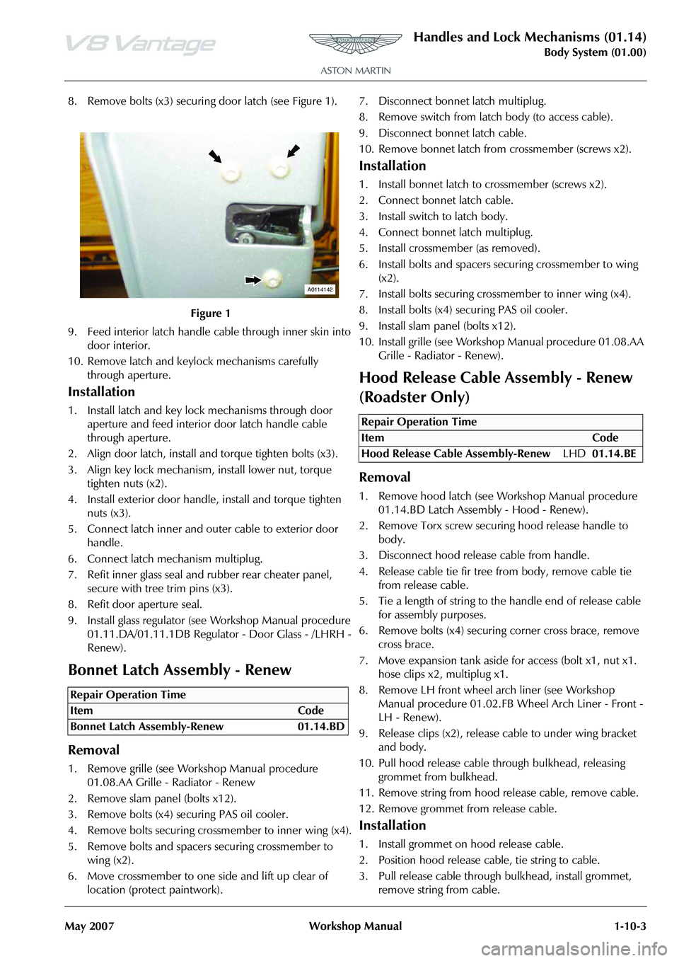
8. Remove bolts (x3) securing door latch (see Figure 1).
9. Feed interior latch handle cable through inner skin into door interior.
10. Remove latch and keylock mechanisms carefully through aperture.
Installation
1. Install latch and key lock mechanisms through door aperture and feed interior door latch handle cable
through aperture.
2. Align door latch, install and torque tighten bolts (x3).
3. Align key lock mechanism, install lower nut, torque tighten nuts (x2).
4. Install exterior door handle, install and torque tighten nuts (x3).
5. Connect latch inner and outer cable to exterior door handle.
6. Connect latch mechanism multiplug.
7. Refit inner glass seal and rubber rear cheater panel, secure with tree trim pins (x3).
8. Refit door aperture seal.
9. Install glass regulator (see Workshop Manual procedure 01.11.DA/01.11.1DB Regulato r - Door Glass - /LHRH -
Renew).
Bonnet Latch Assembly - Renew
Removal
1. Remove grille (see Workshop Manual procedure 01.08.AA Grille - Radiator - Renew
2. Remove slam panel (bolts x12).
3. Remove bolts (x4) securing PAS oil cooler.
4. Remove bolts securing crossmember to inner wing (x4).
5. Remove bolts and spacers securing crossmember to wing (x2).
6. Move crossmember to one side and lift up clear of location (protect paintwork). 7. Disconnect bonnet latch multiplug.
8. Remove switch from latch body (to access cable).
9. Disconnect bonnet latch cable.
10. Remove bonnet latch from
crossmember (screws x2).
Installation
1. Install bonnet latch to crossmember (screws x2).
2. Connect bonnet latch cable.
3. Install switch to latch body.
4. Connect bonnet latch multiplug.
5. Install crossmember (as removed).
6. Install bolts and spacers securing crossmember to wing
(x2).
7. Install bolts securing cros smember to inner wing (x4).
8. Install bolts (x4) securing PAS oil cooler.
9. Install slam panel (bolts x12).
10. Install grille (see Workshop Manual procedure 01.08.AA
Grille - Radiator - Renew).
Hood Release Cable Assembly - Renew
(Roadster Only)
Removal
1. Remove hood latch (see Wo rkshop Manual procedure
01.14.BD Latch Assembly - Hood - Renew).
2. Remove Torx screw securi ng hood release handle to
body.
3. Disconnect hood releas e cable from handle.
4. Release cable tie fir tree fr om body, remove cable tie
from release cable.
5. Tie a length of string to the handle end of release cable for assembly purposes.
6. Remove bolts (x4) securing corner cross brace, remove
cross brace.
7. Move expansion tank aside for access (bolt x1, nut x1. hose clips x2, multiplug x1.
8. Remove LH front wheel arch liner (see Workshop Manual procedure 01.02.FB Wheel Arch Liner - Front -
LH - Renew).
9. Release clips (x2), release cable to under wing bracket and body.
10. Pull hood release cable th rough bulkhead, releasing
grommet from bulkhead.
11. Remove string from hood release cable, remove cable.
12. Remove grommet from release cable.
Installation
1. Install grommet on hood release cable.
2. Position hood release cable, tie string to cable.
3. Pull release cable through bulkhead, install grommet, remove string from cable.
Figure 1
Repair Operation Time
ItemCode
Bonnet Latch Assembly-Renew 01.14.BD
A0114142
Repair Operation Time
ItemCode
Hood Release Cable Assembly-Renew LHD01.14.BE
Page 159 of 947
Convertible Roof (01.17)
Body System (01.00)
May 2007 Workshop Manual 1-12-21
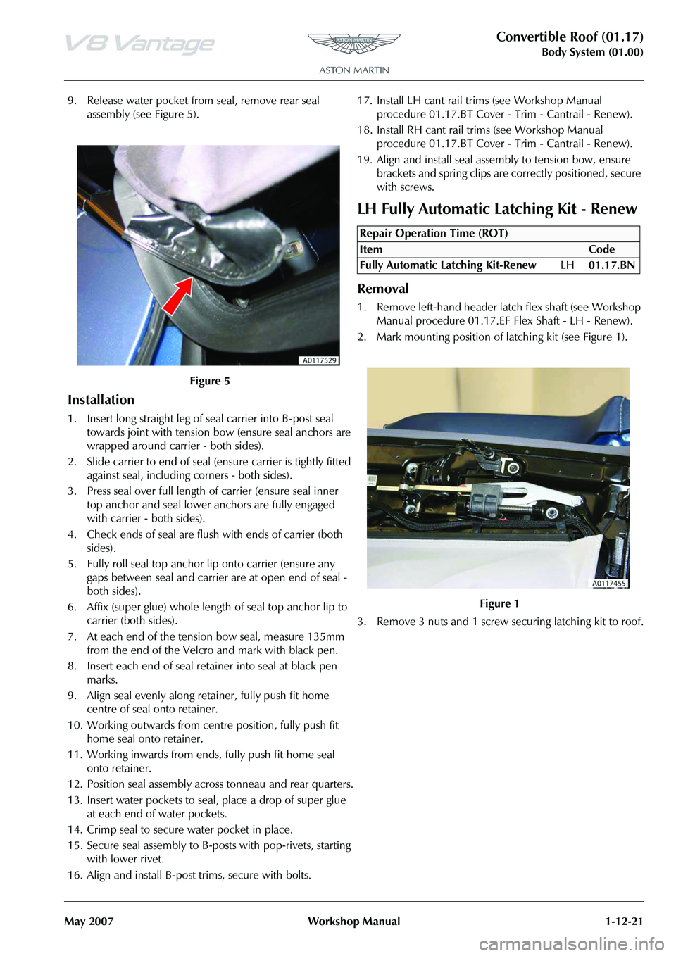
9. Release water pocket from seal, remove rear seal assembly (see Figure 5).
Installation
1. Insert long straight leg of seal carrier into B-post seal
towards joint with tension bo w (ensure seal anchors are
wrapped around carrier - both sides).
2. Slide carrier to end of seal (ensure carrier is tightly fitted
against seal, including corners - both sides).
3. Press seal over full length of carrier (ensure seal inner
top anchor and seal lower anchors are fully engaged
with carrier - both sides).
4. Check ends of seal are flush with ends of carrier (both sides).
5. Fully roll seal top anchor lip onto carrier (ensure any gaps between seal and carrier are at open end of seal -
both sides).
6. Affix (super glue) whole length of seal top anchor lip to carrier (both sides).
7. At each end of the tension bow seal, measure 135mm from the end of the Velcro and mark with black pen.
8. Insert each end of seal retainer into seal at black pen marks.
9. Align seal evenly along retainer, fully push fit home centre of seal onto retainer.
10. Working outwards from cent re position, fully push fit
home seal onto retainer.
11. Working inwards from ends, fully push fit home seal onto retainer.
12. Position seal assembly across tonneau and rear quarters.
13. Insert water pockets to seal, place a drop of super glue at each end of water pockets.
14. Crimp seal to secure water pocket in place.
15. Secure seal assembly to B-posts with pop-rivets, starting with lower rivet.
16. Align and install B-post trims, secure with bolts. 17. Install LH cant rail tr
ims (see Workshop Manual
procedure 01.17.BT Cover - Trim - Cantrail - Renew).
18. Install RH cant rail trims (see Workshop Manual procedure 01.17.BT Cover - Trim - Cantrail - Renew).
19. Align and install seal asse mbly to tension bow, ensure
brackets and spring clips are correctly positioned, secure
with screws.
LH Fully Automatic Latching Kit - Renew
Removal
1. Remove left-hand header latch flex shaft (see Workshop Manual procedure 01.17.EF Flex Shaft - LH - Renew).
2. Mark mounting position of latching kit (see Figure 1).
3. Remove 3 nuts and 1 screw securing latching kit to roof.
Figure 5
Repair Operation Time (ROT)
Page 214 of 947
Restraining Devices (01.20)
Body System (01.00)1-14-2 Workshop Manual May 2007
mounted onto a spindle (torsion bar) which once the sensor
has locked the retractor reel and a predetermined load is
applied, twists and allows additional webbing into the
system. The deceleration force required to initiate this
sequence is approximately th e same as that required to
initiate airbag deployment. The torsion bar load limiting
device will only react if the safety belt is in use at the time of
the impact.
Emergency Locking Retractor (ELR)
The retractors in all seat posi tions feature ELR. During any
period of sudden deceleration, or under lateral load when
cornering at speed, a sensor weight within the safety belt
retractor moves a locking pawl against the teeth on the
retractor reel, which then locks the retractor preventing any
further release of webbing. As soon as the load applied onto
the retractor through the safety belt webbing is removed the
locking pawl releases the retractor reel and normal
movement is returned to the retractor.
Automatic Locking Retractor (ALR)
Automatic locking retractors (ALR) are installed to all
passenger seat positions.
The safety belt webbing on these are clearly marked to show
their operating feature. To initiate the ALR system, fasten the
safety belt into it’s buckle and pull all of the webbing from
the retractor, as the safety belt is released the retractor locks
allowing travel in only one plane thus producing a fixed
length restraint and preventing the safety belt from
introducing slack, making any child seat it may be restraining
secure. The ALR system of the retractor is disengaged by
releasing the safety belt and allowing the safety belt to fully
retract onto the reel. Caution
It should be considered th at during any event that
utilizes the full capability of the safety belts, the
webbing may have been elongated and the torsion bar may have twisted. For this reason, if a vehicle is
involved in an accident which results in the deployment of the airbag(s), all the safety belts that were in use at
the time of the accident MUST be renewed.
Page 236 of 947
Engine Assembly (03.00)
Engine (03.00)3-0-4 Workshop Manual Issue 5, January 2010
Engine (03.00)
Engine Assembly (03.00)
Description
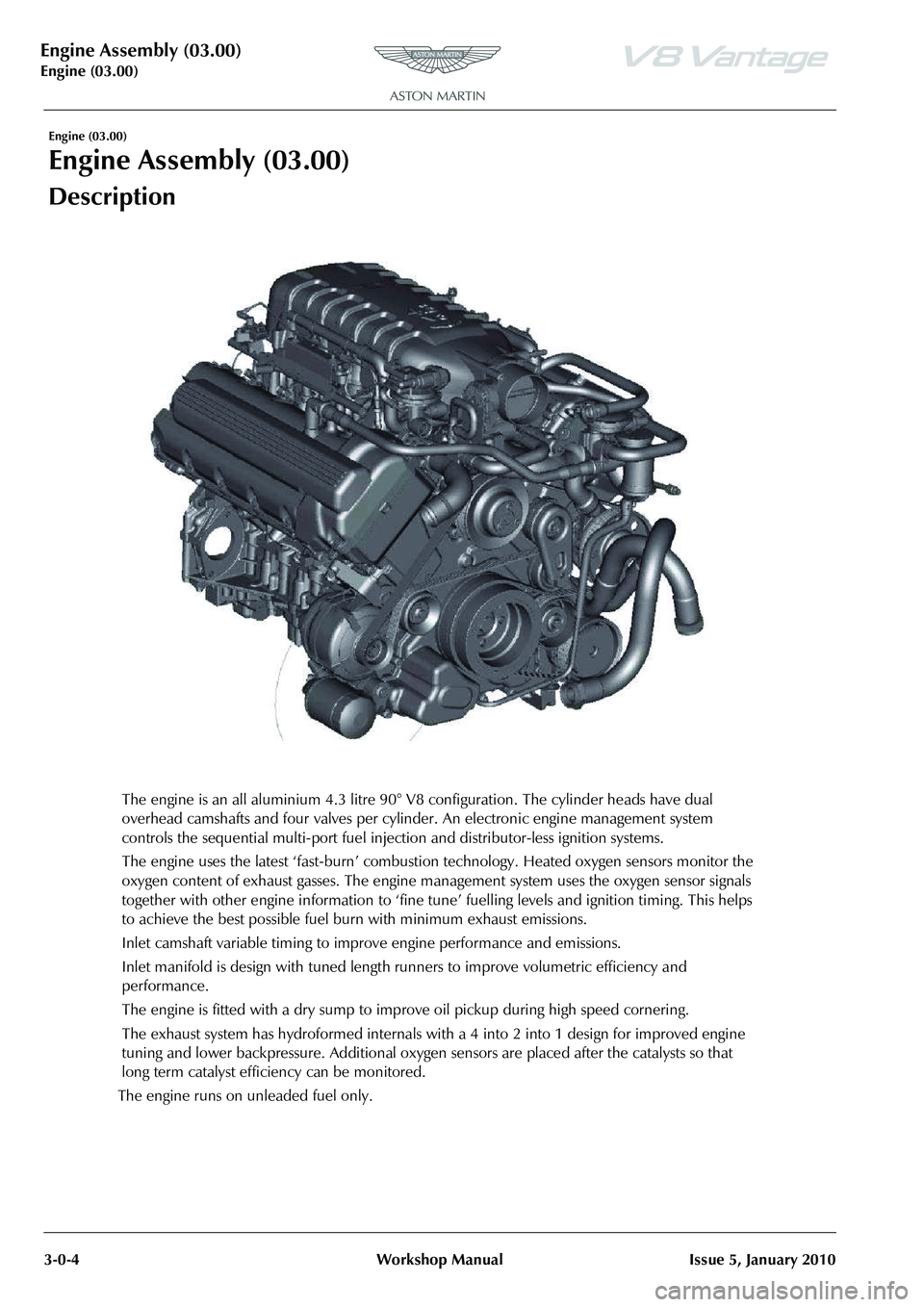
The engine is an all aluminium 4.3 litre 90° V8 configuration. The cylinder heads have dual
overhead camshafts and four valves per cylinder. An electronic engine management system
controls the sequential multi-port fuel injection and distributor-less ignition systems.
The engine uses the latest ‘fast-burn’ combustion technology. Heated oxygen sensors monitor the
oxygen content of exhaust gasses . The engine management system uses the oxygen sensor signals
together with other engine information to ‘fine tune ’ fuelling levels and ignition timing. This helps
to achieve the best possible fuel bur n with minimum exhaust emissions.
Inlet camshaft variable timing to impr ove engine performance and emissions.
Inlet manifold is design with tuned length runners to improve volumetric efficiency and
performance.
The engine is fitted with a dry sump to improv e oil pickup during high speed cornering.
The exhaust system has hydroforme d internals with a 4 into 2 into 1 design for improved engine
tuning and lower backpressure. Additional oxygen sensors are placed after the catalysts so that
long term catalyst efficiency can be monitored.
The engine runs on unleaded fuel only.
Page 262 of 947
Engine Structure (03.01)
3-1-14Workshop ManualIssue 4, November 2008
14. Inspect cylinder head face for warpage, across centre
and from corner to corner.
15. Check condition and measure free length of valve springs.
16. Decarbonise combustion chambers and exhaust ports.
17. Measure valve stem diameters.
18. Use new valves and check valve guide clearance.
Installation
1. Clean cylinder head face and inlet/exhaust manifold faces. Use and air line to completely dry cylinder head
surfaces.
2. Lubricate and install intake and exhaust valves (x16).
3. Install valve stem oil seals.
4. Install valve springs and collars.
5. Using valve spring compressor, compress valve spring, install collets.
6. Release/remove spring compressor.
7. Repeat procedure for remaining valve assemblies.
8. Install selective tappet buckets in their original fitted positions.
9. Lubricate intake camshaft bearings and journals with clean engine oil.
10. Install intake camshaft, install bearing caps (x5), install bolts (x10).
11. Torque tighten bearing cap bolts in the correct sequence.
12. Lubricate exhaust camshaft be arings and journals with
clean engine oil.
13. Install exhaust camshaft, install bearing caps (x5), install bolts (x10).
14. Torque tighten bearing cap bolts in the correct sequence.
15. Install camshaft sprocket Torx bolts in intake and exhaust camshafts.
16. Rotate intake camshaft clockwise, check and log each valve clearance using feeler gauges.
17. Calculate the correct tappet bucket grade.
18. Repeat procedure for exhaust valve clearances.
19. Remove bearing cap bolts (x10), remove bearing caps (x5), remove intake camshaft.
20. Remove tappet buckets, install selected tappet buckets.
21. Repeat procedure for exhaust valve clearances.
22. Install intake camshaft, install bearing caps (x5), install bolts (x10).
23. Torque tighten bearing cap bolts in the correct sequence.
24. Rotate intake camshaft clockwise, re-check each valve clearance using feeler gauges.
25. Repeat procedure and re-check exhaust valve clearances.
26. Remove camshaft sprocket Torx bolts (x2).
27. Remove bearing cap bolts (x10), remove bearing caps (x5), remove intake camshaft. 28. Remove bearing cap bolts (x10), remove bearing caps
(x5), remove exhaust camshaft.
29. Clean EGR tube.
30. Install new gasket, install EGR tube to cylinder head, install and torque tighten Torx screws (x2).
31. Clean Knock sensors (x2).
32. Install knock sensors (x2) to cylinder head, install and torque tighten bolts (x2).
33. Clean camshaft timing sensor.
34. Install camshaft timing sensor, install and torque tighten bolt.
35. Install spark plugs.
36. Install cylinder head gasket RH (see Workshop Manual procedure 03.01.GU Gasket - Cylinder Head - RH -
Renew).
Cylinder Head (Engine Set) - Overhaul
Removal
1. Remove cylinder head gaskets - engine set (see Workshop Manual procedure 03.10.AL Gasket -
Cylinder Head - Engine Set - Renew).
2. Remove Torx screws (x4) securing EGR tubes to cylinder heads, remove tubes.
3. Remove and discard gaskets.
4. Remove bolts (x2) securing camshaft timing sensors to cylinder heads, remove sensors.
5. Remove bolts (x4) securing knock sensors (x4) to cylinder heads, remove sensors.
6. Remove spark plugs from cylinder heads (x8).
7. Remove selective tappet buckets, keep in their fitted order.
8. Position valve spring compressor, compress valve springs.
9. Remove collets, release/remove spring compressor, collect collars and valve springs.
10. Remove valves from cylinder heads.
11. Remove valve stem oil seals.
12. Keep valves and springs in their fitted order.
13. Inspect cylinder head face for warpage, across centre and from corner to corner.
14. Check condition and measure free length of valve springs.
15. Decarbonise combustion chambers and exhaust ports.
16. Use new valves and check valve guide clearances.
Installation
1. Clean cylinder head face and inlet/exhaust manifold faces. Use and air line to completely dry cylinder head
surfaces.
Repair Operation Time (ROT)
ItemCode
Cylinder Head (Engine Set)-Overhaul LHD03.01.GZ
Cylinder Head (Engine Set)-Overhaul RHD03.01.FZ
Page 263 of 947
Engine Structure (03.01)
Issue 4, November 2008Workshop Manual 3-1-15
2. Lubricate and install intake and exhaust valves (x16).
3. Install valve stem oil seals.
4. Install valve springs and collars.
5. Using valve spring compressor, compress valve spring,
install collets.
6. Release/remove spring compressor.
7. Install selective tappet buckets in their original fitted positions.
8. Lubricate intake and exha ust camshaft bearings and
journals with clean engine oil.
9. Install intake and exhaust camshafts, install bearing caps (x20), install bolts (x40).
10. Torque tighten bearing cap bolts in the correct sequence.
11. Install camshaft sprocket Torx bolts in intake and exhaust camshafts.
12. Rotate intake camshaft cl ockwise, check and log each
valve clearance using feeler gauges.
13. Calculate the correct tappet bucket grade.
14. Remove bearing cap bolts (x40), remove bearing caps
(x20), remove intake and exhaust camshafts.
15. Remove tappet buckets, install selected tappet buckets.
16. Install intake and exhaust camshafts, install bearing caps (x20), install bolts (x40).
17. Torque tighten bearing cap bolts in the correct sequence.
18. Rotate intake and exhaus t camshafts clockwise, re-
check each valve clearance using feeler gauges.
19. Remove camshaft sprocket Torx bolts (x4).
20. Remove bearing cap bolts (x40), remove bearing caps
(x20), remove intake and exhaust camshafts.
21. Clean EGR tubes.
22. Install new gaskets, install EGR tubes to cylinder heads, install and torque tighten Torx screws (x4).
23. Clean Knock sensors (x4).
24. Install knock sensors (x4) to cylinder head, install and torque tighten bolts (x4).
25. Clean camshaft timing sensors.
26. Install camshaft timing sensor, install and torque tighten bolt.
27. Install spark plugs.
28. Install cylinder head gaskets - engine set (see Workshop Manual procedure 03.10.AL Gasket - Cylinder Head -
Engine Set - Renew).
Valve Set (Engine Set) - Renew (including
de-coke)
Removal
1. Remove cylinder head gaskets - engine set (see Workshop Manual procedure 03.10.AL Gasket -
Cylinder Head - Engine Set - Renew).
2. Remove spark plugs (x8).
3. Remove selective tappet buckets, keep in their fitted order.
4. Position valve spring compressor, compress valve spring.
5. Remove collets, release/remove spring compressor, collect collar and valve spring.
6. Remove valves from cylinder.
7. Remove valve stem oil seals.
8. Keep valves and springs in their fitted order.
9. Inspect cylinder head face for warpage, across centre and from corner to corner.
10. Check condition and measure free length of valve springs.
11. Decarbonise combustion chambers and exhaust ports.
12. Use new valves and check valve guide clearances.
Installation
1. Clean cylinder head face and inlet/exhaust manifold faces. Use and air line to completely dry cylinder head
surfaces.
2. Lubricate and install intake and exhaust valves (x32).
3. Install valve stem oil seals.
4. Install valve springs and collars.
5. Using valve spring compressor, compress valve spring, install collets.
6. Release/remove spring compressor.
7. Install selective tappet buckets in their original fitted positions.
8. Lubricate intake and exhaust camshaft bearings and journals with clean engine oil.
9. Install intake and exhaust camshafts, install bearing caps (x20), install bolts (x40).
10. Torque tighten bearing cap bolts in the correct sequence.
11. Install camshaft sprocket Torx bolts in intake and exhaust camshafts.
12. Rotate intake camshaft clockwise, check and log each valve clearance using feeler gauges.
13. Calculate the correct tappet bucket grade.
14. Remove bearing cap bolts (x40), remove bearing caps (x20), remove intake and exhaust camshafts.
15. Remove tappet buckets, install selected tappet buckets.
16. Install intake and exhaust camshafts, install bearing caps (x20), install bolts (x40).
17. Torque tighten bearing cap bolts in the correct sequence.
18. Rotate intake and exhaust camshafts clockwise, re- check each valve clearance using feeler gauges.
19. Remove camshaft sprock et Torx bolts (x4).
Repair Operation Time (ROT)
Page 264 of 947
Engine Structure (03.01)
3-1-16Workshop ManualIssue 4, November 2008
20. Remove bearing cap bolts (x40), remove bearing caps
(x20), remove intake and exhaust camshafts.
21. Install spark plugs.
22. Install cylinder head gaskets - engine set (see Workshop Manual procedure 03.10.AL Gasket - Cylinder Head -
Engine Set - Renew).
Inlet Valve (Set) - Renew
Removal
1. Remove cylinder head gaskets - engine set (see Workshop Manual procedure 03.10.AL Gasket -
Cylinder Head - Engine Set - Renew).
2. Remove spark plugs from cylinder head.
3. Remove intake selective tappet buckets from cylinder heads, keep in their fitted order.
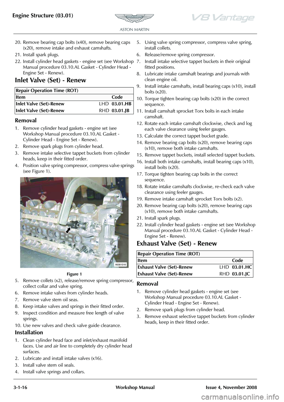
4. Position valve spring compressor, compress valve springs (see Figure 1).
Figure 1
5. Remove collets (x2), releas e/remove spring compressor,
collect collar and valve spring.
6. Remove intake valves from cylinder heads.
7. Remove valve stem oil seas.
8. Keep intake valves and springs in their fitted order.
9. Inspect condition and measure free length of valve springs.
10. Use new valves and check valve guide clearance.
Installation
1. Clean cylinder head face and inlet/exhaust manifold faces. Use and air line to completely dry cylinder head
surfaces.
2. Lubricate and install intake valves (x16).
3. Install valve stem oil seals.
4. Install valve springs and collars. 5. Using valve spring compressor, compress valve spring,
install collets.
6. Release/remove spring compressor.
7. Install intake selective tappet buckets in their original fitted positions.
8. Lubricate intake camshaft bearings and journals with clean engine oil.
9. Install intake camshafts, inst all bearing caps (x10), install
bolts (x20).
10. Torque tighten bearing cap bolts (x20) in the correct sequence.
11. Install camshaft sprocket Torx bolts in each intake
camshaft.
12. Rotate each intake camshaft clockwise, check and log each valve clearance using feeler gauges.
13. Calculate the correct tappet bucket grade.
14. Remove bearing cap bolts (x20), remove bearing caps (x10), remove both intake camshafts.
15. Remove tappet buckets, install selected tappet buckets.
16. Install both intake camshaf ts, install bearing caps (x10),
install bolts (x20).
17. Torque tighten bearing cap bolts in the correct sequence.
18. Rotate intake camshafts clockwise, re-check each valve clearance using feeler gauges.
19. Remove intake camshaft sp rocket Torx bolts (x2).
20. Remove bearing cap bolts (x20), remove bearing caps (x10), remove both intake camshafts.
21. Install spark plugs.
22. Install cylinder head gaskets - engine set (see Workshop Manual procedure 03.10.AL Gasket - Cylinder Head -
Engine Set - Renew).
Exhaust Valve (Set) - Renew
Removal
1. Remove cylinder head gaskets - engine set (see Workshop Manual procedure 03.10.AL Gasket -
Cylinder Head - Engine Set - Renew).
2. Remove spark plugs from cylinder head.
3. Remove exhaust selective tappet buckets from cylinder heads, keep in their fitted order.
Repair Operation Time (ROT)
A0301310
Repair Operation Time (ROT)
ItemCode
Exhaust Valve (Set)-Renew LHD03.01.HC
Exhaust Valve (Set)-Renew RHD03.01.JC
Page 265 of 947
Engine Structure (03.01)
Issue 4, November 2008Workshop Manual 3-1-17
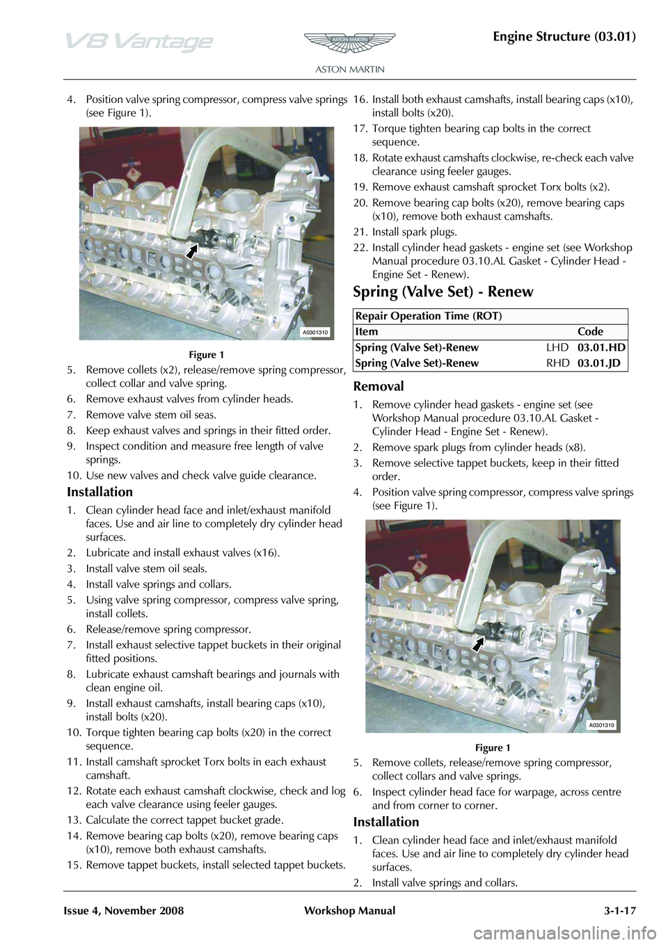
4. Position valve spring compressor, compress valve springs
(see Figure 1).
Figure 1
5. Remove collets (x2), release/remove spring compressor, collect collar and valve spring.
6. Remove exhaust valves from cylinder heads.
7. Remove valve stem oil seas.
8. Keep exhaust valves and springs in their fitted order.
9. Inspect condition and measure free length of valve springs.
10. Use new valves and check valve guide clearance.
Installation
1. Clean cylinder head face and inlet/exhaust manifold faces. Use and air line to completely dry cylinder head
surfaces.
2. Lubricate and install exhaust valves (x16).
3. Install valve stem oil seals.
4. Install valve springs and collars.
5. Using valve spring compressor, compress valve spring, install collets.
6. Release/remove spring compressor.
7. Install exhaust selective tappet buckets in their original fitted positions.
8. Lubricate exhaust camshaft be arings and journals with
clean engine oil.
9. Install exhaust camshafts, install bearing caps (x10), install bolts (x20).
10. Torque tighten bearing cap bolts (x20) in the correct
sequence.
11. Install camshaft sprocket Torx bolts in each exhaust camshaft.
12. Rotate each exhaust camshaf t clockwise, check and log
each valve clearance using feeler gauges.
13. Calculate the correct tappet bucket grade.
14. Remove bearing cap bolts (x20), remove bearing caps
(x10), remove both exhaust camshafts.
15. Remove tappet buckets, install selected tappet buckets. 16. Install both exhaust camshaft
s, install bearing caps (x10),
install bolts (x20).
17. Torque tighten bearing cap bolts in the correct sequence.
18. Rotate exhaust camshafts clockwise, re-check each valve clearance using feeler gauges.
19. Remove exhaust camshaft sprocket Torx bolts (x2).
20. Remove bearing cap bolts (x20), remove bearing caps (x10), remove both exhaust camshafts.
21. Install spark plugs.
22. Install cylinder head gaskets - engine set (see Workshop Manual procedure 03.10.AL Gasket - Cylinder Head -
Engine Set - Renew).
Spring (Valve Set) - Renew
Removal
1. Remove cylinder head gaskets - engine set (see Workshop Manual procedure 03.10.AL Gasket -
Cylinder Head - Engine Set - Renew).
2. Remove spark plugs from cylinder heads (x8).
3. Remove selective tappet buckets, keep in their fitted order.
4. Position valve spring compressor, compress valve springs (see Figure 1).
Figure 1
5. Remove collets, release/remove spring compressor, collect collars and valve springs.
6. Inspect cylinder head face for warpage, across centre and from corner to corner.
Installation
1. Clean cylinder head face and inlet/exhaust manifold faces. Use and air line to completely dry cylinder head
surfaces.
2. Install valve springs and collars.
A0301310
Repair Operation Time (ROT)
A0301310
Page 275 of 947
Lubrication System (03.02)
Engine (03.00)
Issue 5, Janauary 2010 Workshop Manual 3-2-1
Engine (03.00)
Lubrication System (03.02)
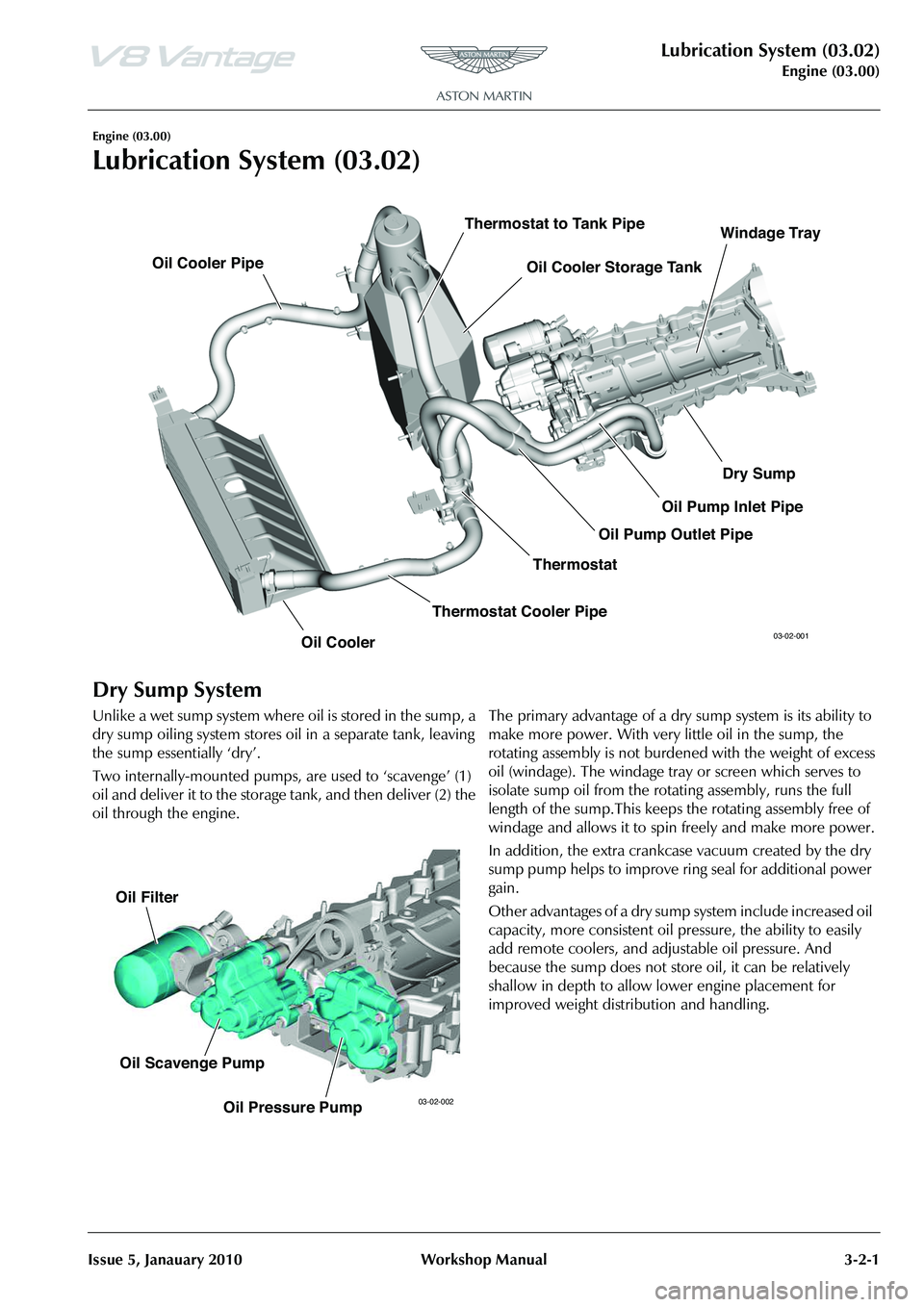
Dry Sump System
Unlike a wet sump system where oil is stored in the sump, a
dry sump oiling system stores oil in a separate tank, leaving
the sump essentially ‘dry’.
Two internally-mounted pumps, are used to ‘scavenge’ (1)
oil and deliver it to the storage tank, and then deliver (2) the
oil through the engine. The primary advantage of a dry sump system is its ability to
make more power. With very little oil in the sump, the
rotating assembly is not burdened with the weight of excess
oil (windage). The windage tray or screen which serves to
isolate sump oil from the rota
ting assembly, runs the full
length of the sump.This keeps the rotating assembly free of
windage and allows it to spin freely and make more power.
In addition, the extra crankcase vacuum created by the dry
sump pump helps to improve ring seal for additional power
gain.
Other advantages of a dry sump system include increased oil
capacity, more consistent oil pr essure, the ability to easily
add remote coolers, and adjustable oil pressure. And
because the sump does not stor e oil, it can be relatively
shallow in depth to allow lower engine placement for
improved weight distribution and handling.
Oil Cooler Oil Cooler Storage Tank
Oil Cooler Pipe
Thermostat
Thermostat to Tank Pipe
Thermostat Cooler Pipe Dry Sump
Oil Pump Outlet Pipe Oil Pump Inlet PipeWindage Tray03-02-001
Oil Filter
Oil Scavenge Pump Oil Pressure Pump
03-02-002
Page 417 of 947
Engine Management System (03.14)
Engine (03.00)
Issue 5, Janauary 2010 Workshop Manual 3-14-1
Engine (03.00)
Engine Management System (03.14)
Maintenance
LH Front Lower Heated Exhaust Gas
Oxygen (HEGO) Sensor - Renew
Removal
1. Raise vehicle on ramp.
2. Remove rear exhaust silencer (refer to Workshop Manual procedure 09.00.KA Silencer and Bypass Valve
Assembly - Remo ve for Access and Refit).
3. Disconnect multiplugs (x2), HEGO sensors.
4. Secure sufficient lengths of string to HEGO sensor multiplugs for assembly purposes.
5. Loosen LH and RH clamp nuts, catalysts to centre pipes.
6. With assistance, manoeuvre exhaust centre pipe assembly rearwards to release from catalysts.
7. Remove nuts (x3), catalyst to exhaust manifold.
8. Release and support weight of LH catalyst from exhaust
manifold.
9. Manoeuvre HEGO sensor leads and remove cable tie. Release HEGO sensor leads from behind heat shield.
Remove string from HEGO multiplugs.
10. Remove catalyst assembly.
11. Remove and discard gasket.
12. Remove HEGO sens ors from catalyst.
Installation
1. Clean catalyst, mating joint faces and HEGO sensors.
2. Install and tighten HEGO sensor to catalyst.
3. Apply proprietary exhaust se alant around clamp joints.
4. Install new gasket to exhaust manifold.
5. Position catalyst, secure string (x2) to HEGO multiplugs, feed sensor leads behind heat shield. Install catalyst to
exhaust manifold.
6. Instal land tighten nuts (x3), catalyst to exhaust manifold.
7. Align centre pipe assembly to catalyst, tighten clamp
nuts.
8. Remove string (x2), conne ct multiplugs (x2), HEGO
sensors.
9. Install rear exhaust silencer (refer to Workshop Manual procedure 09.00.KA Silencer and Bypass Valve
Assembly - Remo ve for Access and Refit).
10. Lower vehicle on ramp.
LH Front Upper Heated Exhaust Gas
Oxygen (HEGO) Sensor - Renew
Repair Operation Time (ROT)
Repair Operation Time (ROT)
WA R N I N G
THE EXHAUST SYSTEM WILL BE VERY HOT AFTER OPERATION. LET THE EXHAUST SYSTEM COOL
BEFORE YOU DO WORK. IF YOU DO NOT, SEVERE
INJURY CAN OCCUR.
Repair Operation Time (ROT)