heating ASTON MARTIN V8 VANTAGE 2010 User Guide
[x] Cancel search | Manufacturer: ASTON MARTIN, Model Year: 2010, Model line: V8 VANTAGE, Model: ASTON MARTIN V8 VANTAGE 2010Pages: 947, PDF Size: 43.21 MB
Page 692 of 947

Wiring and Circuit Protection (18.01)
Electric Distribution/Electronic Control (18.00)
May 2007 Workshop Manual 18-1-3
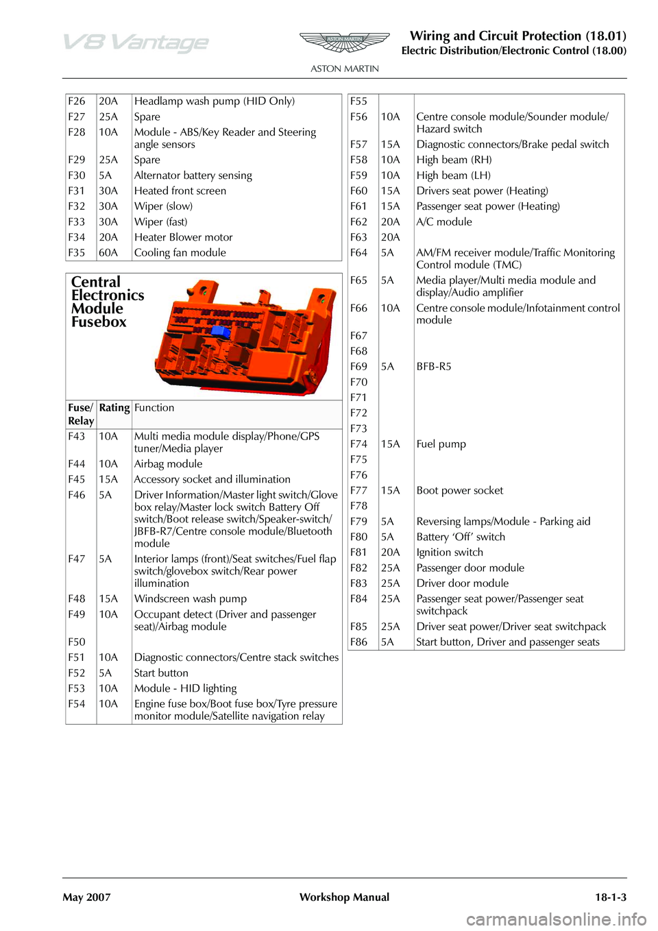
F26 20A Headlamp wash pump (HID Only)
F27 25A Spare
F28 10A Module - ABS/Key Reader and Steering angle sensors
F29 25A Spare
F30 5A Alternator battery sensing
F31 30A Heated front screen
F32 30A Wiper (slow)
F33 30A Wiper (fast)
F34 20A Heater Blower motor
F35 60A Cooling fan module
Central
Electronics
Module
Fusebox
Fuse/
RelayRatingFunction
F43 10A Multi media module display/Phone/GPS tuner/Media player
F44 10A Airbag module
F45 15A Accessory socket and illumination
F46 5A Driver Information/Master light switch/Glove box relay/Master lock switch Battery Off
switch/Boot release switch/Speaker-switch/
JBFB-R7/Centre console module/Bluetooth
module
F47 5A Interior lamps (front)/Seat switches/Fuel flap switch/glovebox switch/Rear power
illumination
F48 15A Windscreen wash pump
F49 10A Occupant detect (Driver and passenger seat)/Airbag module
F50
F51 10A Diagnostic connectors/Centre stack switches
F52 5A Start button
F53 10A Module - HID lighting
F54 10A Engine fuse box/Boot fuse box/Tyre pressure monitor module/Satellite navigation relay
F55
F56 10A Centre console module/Sounder module/
Hazard switch
F57 15A Diagnostic connectors/Brake pedal switch
F58 10A High beam (RH)
F59 10A High beam (LH)
F60 15A Drivers seat power (Heating)
F61 15A Passenger seat power (Heating)
F62 20A A/C module
F63 20A
F64 5A AM/FM receiver module/Traffic Monitoring Control module (TMC)
F65 5A Media player/Multi media module and display/Audio amplifier
F66 10A Centre console module/Infotainment control module
F67
F68
F69 5A BFB-R5
F70
F71
F72
F73
F74 15A Fuel pump
F75
F76
F77 15A Boot power socket
F78
F79 5A Reversing lamps/Module - Parking aid
F80 5A Battery ‘Off’ switch
F81 20A Ignition switch
F82 25A Passenger door module
F83 25A Driver door module
F84 25A Passenger seat power/Passenger seat switchpack
F85 25A Driver seat power/Driver seat switchpack
F86 5A Start button, Driver and passenger seats
Page 933 of 947

System
Component
P Codes (AML)
Malfunction Strategy Description
Malfunction Criteria
(Fault)
Fault condition
(Internal labels)
Threshold Value
(Fault condition)
Entry conditions
Entry conditions values
Filter Time to log DTC (AML)
EMS controlled MIL Illumination
(AML)
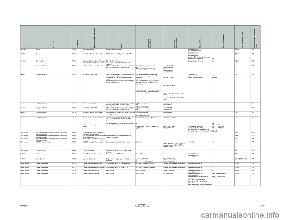
CAN LinkEngine P0725Engine speed signal
Engine Speed signal QF ≠ 3 No CAN BUS error.
No CAN level error and
No EMS timeout.600mS
1 DTC
CAN Link CAN level P0614Incorrect configuration ID received CANid does not match that stored in the TCM Engine not in crank.
No CAN BUS error
Ignition on & Timer after ignition passed.
Battery Voltage > threshold7v250mS
1 DTC
CAN Link CAN bus off P1796Monitors the CAN for Bus or RAM faults.
TCM CAN driver detects CAN bus fault. Bit, stuff, CRC or form error,
(CAN-wiring or CAN-module defective, EMC
radiation.) Battery voltage > Threshold
7v100mS1 DTC
Sensor Temperature Sensor P0711 ATF temperature sensor short circuit ATF sensor faulty - Sensor input signals (Vcgt_plus
and Vcgt_minus) out of acceptable range utmsm2_Gt
utmsm2_Gt
and
utmsm2_Gt =2.3v
utmsm1_Gt =2.7v 1.5s
2 DTC
Sensor Temperature Sensor P0711ATF Sensor - stuck value Stuck Temperature value - ATF temperature is out
of an acceptable range of tolerance when
compared to the TCM chip temperature sensor
value.
Range of tolerance is depending on the heating up
velocity of transmission . [
Fast heating = wide range of tolerance :
Chip sensor temp +/- cgt_tolwt <> ATF
temperature
OR
Slow heating = narrow range of tolerance :
Chip sensor temp +/- cgt_toleng <> ATF
temperature.]
AND
Temperature cgtf_Neu out of allowed range of
tolerance for > zgts_CgtPlausiErr * 100ms cgt_tolwt = 40degC
cgt_toleng = 25degC
AML: zgts_CgtPlausiErr= 6000 ( =
10min)
Jag+LR: zgts_CgtPlausiErr= 9000 ( =
15min)Chip sensor OK
Engine speed > threshold
Turbine speed > threshold
450rpm
450rpm1.5s
2 DTC
Sensor Temperature Sensor P0713ATF Sensor short to battery ATF sensor faulty - Sensor input signals (Vcgt_plus
and Vcgt_minus) out of acceptable range vcgt_plus > utmso_Gt
and
vcgt_minus > utmsu_Gtutmso_Gt = 4.5v
utmsu_Gt =0.5v
1.5s
2 DTC
Sensor Temperature Sensor P0712ATF Sensor short to GND ATF sensor faulty - Sensor input signals (Vcgt_plus
and Vcgt_minus) out of acceptable range vcgt_plus < utmso_Gt
and
vcgt_minus < utmsu_Gtutmso_Gt = 4.5v
utmsu_Gt =0.5v
1.5s
2 DTC
Sensor Temperature Sensor P0714ATF sensor open cct (circuit break) ATF sensor faulty - Sensor input signals (Vcgt_plus
and Vcgt_minus) out of acceptable range vcgt_plus > utmso_Gt
and
vcgt_minus < utmsu_Gtutmso_Gt = 4.5v
utmsu_Gt =0.5v
1.5s
2 DTC
Sensor Temperature Sensor P0713 ATF temperature sensor value jump
or
ATF value not warming up quickly
enough Unacceptable temperature jump (lOld value - new
value <> threshold) within a period of 100ms
or
ATF temperature (cgt_neu) not warming up quickly
enough within a specified time period
|cgt_Neu - cgta1_CUew| > cgtd1_Cuew
or
(cgt_Neu(t=tgtd_CUew) - cgt_Neu(t=0) ) <
cgtd2_Cuewcgtd1_Cuew = 20DegC
cgtd2_Cuew = 4DegC
tgtd_CUEW = 240s
Output speed > Threshold
Engine speed > Threshold
No Output speed & Engine speed error
Temperature cgt_Neu < Threshold at t=0Jag +
AML / LR
800 / 11000rpm
400 / 11000rpm
20DegC1.5s
2 DTC
TCM Internal Impossible substitute functions (monitoring contradictory
substitute functions) P0701
Two Priority 2 faults present at the same
time (Currently not possible) 20ms
2 DTC
TCM Internal Impossible substitute functions (monitoring contradictory
substitute functions) P0701
OSS fault and wheel speed faults present
concurrently (Priority 3) Wheel speed and output speed sensor faults
present concurrently. 20ms
2 DTC
TCM Internal Impossible substitute functions (monitoring contradictory
substitute functions) P0701
Bosch solenoid current monitorin
g fault 20ms 2 DTC
TCM Internal EEPROM Flash emulation P062FEEPROM emulation lifetime exceeded Communication disturbed, lifetime exceeded EEError !=0 =1
400000 Write/Erase-cycles possible. At
temperatures over 135°C no EEProm
update is made.always active
no0mS1 DTC
TCM Internal FLASH checksum P1603Checksum incorrect Calculated checksum does not match stored
checksum 0mS
2 DTC
CAN Link Engine P1719Engine Torque signal inaccurate
Engine torque signal QF 0 = 3 fcn_MmmErr
=1No CAN BUS error.
No CAN level error
and No EMS timeout. 600ms
2 DTC
CAN Link Engine Speed P1920Engine speed too high Engine Speed > Engine speed threshold> for a time
threshold n_mot > NS_MOTUEB
&
Timer_nmotueb > T_FNMOTUEBNS_MOTUEB = 7100rpm
T_FNMOTUEB=2550mS T_FNMOTUEB=2550mS 2 DTC
Speed Sensors Turbine speed sensor P0715Turbine speed sensor s/c to battery
supply Turbine speed sensor s/c to battery supply sgt_DiNtu = 2 (short circuit to plus)
2 (Status of turbine speed sensor signal. Sensor supply voltage OK0600mS2 DTC
Speed Sensors Turbine speed sensor P0717Turbine speed sensor s/c to gnd or O/C Turbine speed sensor s/c to gnd or O/C sgt_DiNtu = 0 (short to gnd or OC)0 (Status of turbine speed sensor signal. Sensor supply voltage OK 0600mS2 DTC
Speed Sensors Turbine speed sensor P0716Turbine Speed Value too high Value too high NTU >= NTUmaxntumax = 8000rpmSensor supply voltage OK
No electrical error 0
600mS2 DTC
Speed Sensors Turbine speed sensor P0716Turbine Speed Value too low Value too low NTU < ntu_Minntu_min = 20 rpmSensor supply voltage OK
No electrical error
engine speed NMO is higher than a
threshold:
status of NMO-signal is alright
output speed NAB is higher than a
threshold:
status of NAB-signal is alright or substitute
fltfl fb Ei t t
nmos_TuUew = 600rpm
nabs_TuUew = 250rpm 600mS
2 DTC
8ASXV05.9VH1 Aston Martin
Auto Gearbox Summary Jan 2008