wheel bolt torque ASTON MARTIN V8 VANTAGE 2010 User Guide
[x] Cancel search | Manufacturer: ASTON MARTIN, Model Year: 2010, Model line: V8 VANTAGE, Model: ASTON MARTIN V8 VANTAGE 2010Pages: 947, PDF Size: 43.21 MB
Page 229 of 947
Subframes (02.03)
Frame and Mounting (02.00)
May 2007 Workshop Manual 2-1-7
15. Use tool (206-103) and release each handbrake cable from mounting brackets, re lease inner cable eyelets
from calliper levers.
16. Remove bolts (x2) and nuts (x2), handbrake cables to subframe.
17. Use tool (206-103) and release handbrake cables from subframe brackets.
18. Release handbrake cable from clip, tie handbrake cable aside.
19. Loosen and disconnect each brake pipe from body bracket. Plug brake pipes
.
20. Remove bolt, fuel filler pipe to damper mounting.
21. Remove nut securing fuel fi ller pipe to body, tie filler
pipe aside.
22. Remove bolts (x4 each side), securing spring/damper assemblies.
23. Position drain tray to collect oil spillage.
24. Loosen and disconnect unions (x2), transaxle oil cooler.
Plug pipe connections.
25. Remove drain tray.
26. Disconnect multiplug, release harness clips (x2), transaxle harness, RH rear wheel arch.
27. Mark subframe position to body.
28. Position subframe trolley (303-F715), under subframe.
29. Lower vehicle until subfra me rests on support trolley.
30. Remove bolts (x6), securing subframe to body.
31. Raise vehicle to gain access to gear selector cables.
32. Using (308-642), release se lector cables (x2) from ball
joints, release selector cables from bracket.
33. Remove torque tube to transaxle bolts (x8).
34. Move subframe support trolley rearwards to give a clearance between torque tube and transaxle.
35. Carefully raise vehicle from subframe.
Installation
1. Clean transaxle and mating face on torque tube.
2. Position subframe assembly underneath vehicle.
3. Lower vehicle to align transaxle to propshaft splines.
4. Move subframe assembly forward, engage propshaft splines, locating dowels, transaxle to torque tube.
5. Install bolts (x8), torque tube to transaxle, torque tighten bolts.
6. Install gear selector cables on levers and in bracket.
7. Lower vehicle onto subframe mountings, align to marks, install and torque tighten bolts (x6).
8. Position spring/damper assemblies, install bolts (x8).
9. Position fuel filler pipe, install and torque tighten bolt.
10. Position fuel filler pipe to body, install and tighten nut to correct torque.
11. Position handbrake cables to subframe, install bolts (x4), torque bolts. 12. Install handbrake cables to callipers.
13. Remove plugs, install brake pipes.
14. Remove plugs, install transaxle oil cooler pipes, tighten
unions to correct torque.
15. Position earth lead to transaxle, install and torque tighten bolt.
16. Install transaxle harness multiplug, secure harness clips (x2).
17. Install shear plate, install and torque tighten bolts (x8).
18. Install heat shield, install and torque tighten bolts (x4).
19. Clean exhaust pipe connections, apply exhaust sealant to connections.
20. Install centre pipe to mountings and catalysts, torque tighten clamp nuts.
21. Install rear exhaust pipes to centre pipe, torque tighten clamp nuts.
22. Position subframe cross brace, install and torque bolts.
23. Install rear muffler (see Workshop Manual procedure 09.00.KA Silencer and Bypass Valve Assembly - Remove
for Access and Refit).
24. Install LH rear wheel arch liner (see Workshop Manual procedure 01.02.JB Wheel Arch Liner - Rear - LH -
Renew).
25. Install RH rear wheel arch liner (see Workshop Manual procedure 01.02.HB Wheel Arch Liner - Rear - RH -
Renew).
26. Bleed brake system (see Workshop Manual procedure 06.07.DD Brake Hydraulic System - Flush/Refill/Bleed
27. Adjust handbrake (see Wo rkshop Manual procedure
06.05.DC Handbrake Cable Assembly - Adjust).
28. Install road Wheel(s).
29. Lower vehicle on ramp and remove safety equipment.
Rear Subframe-Remove/Refit
Removal
1. Disconnect vehicle battery.
2. Remove rear subframe asse mbly (see Workshop Manual
procedure 02.01.CA Subframe Assembly - Rear -
Remove for Access and Refit).
3. Mark driveshafts to transaxle flanges for assembly purposes.
4. Remove and discard Allen bolts (x12), collect plates (x6), driveshaft flanges to transaxle.
5. Attach slings to transaxle, connect suitable hoist and
take weight of transaxle.
6. Remove nuts (x2). hydramounts to subframe.
7. With assistance, raise and remove transaxle from subframe.
Caution
Always plug pipe connections to prevent ingress of dirt.
Repair Operation Time (ROT)
Page 230 of 947
Subframes (02.03)
Frame and Mounting (02.00)
2-1-8 Workshop Manual May 2007
8. Remove bolts (x2), remove both spring/damper assemblies.
9. Remove nuts (x2), anti-roll bar links to lower suspension
arms.
10. Remove bolts (x4). anti-roll bar to subframe. Remove anti-roll bar.
11. Disconnect ABS sensor mult iplugs (x2), release sensor
harness clips (x4) from both toe control arms.
12. Disconnect brake pad wear sensor multiplugs (x2). Release connectors (x2) from subframe.
13. Loosen and disconnect brake pipe unions (x2) from subframe brackets. Pl ug pipe connections.
14. Disconnect multiplug fr om ride height sensor.
15. Remove nut/bolt securing ride height sensor link to
upper suspension arm.
16. Remove bolts (x2), ride height sensor to subframe. Remove sensor.
17. Remove nuts/bolts (x2) and cam washers (x2), toe control arms to subframe.
18. Remove bolts (x2), nuts/bolts (x2) and cam washers (x2),
securing lower suspension arms to subframe
19. Remove nuts/bolts (x4), upper suspension arms to subframe.
20. With assistance, remove suspension assemblies from subframe.
21. Remove heatshield clips (x2) from rear of subframe.
22. Release clips (x23), ha rness to subframe, remove
harness.
23. Release brake pipes from cl ips (x7), remove pipes (x2).
24. Remove brake pipe clips (x5) from subframe.
Installation
1. Clean suspension components and brake pipes.
2. Instal brake pipe clips (x5) in subframe.
3. Install brake pipes (x2) in clips (x7).
4. Install harness and secure with clips (x23).
5. Install heatshield clips (x2).
6. With assistance, install suspension assemblies in subframe.
7. Install bolts/nuts (x4), upper suspension arm to subframe. Do not torque tighten at this stage.
8. Install bolts (x2), bolts/nuts (x2) and cam washers (x2) securing lower suspension arm to subframe. Do not
torque tighten at this stage.
9. Position toe control arm, install bolts (x2, cam washers (x2 and nuts (x2). Do not torque tighten at this stage.
10. Install ride height sensor, in stall and torque tighten bolts
(x2).
11. Align ride height sensor li nk to upper suspension arm,
install bolt/nut, tighten to correct torque.
12. Connect multiplug to ride height sensor. 13. Remove pipe plugs, install and torque tighten brake
pipe unions.
14. Connect brake pad wear sensor multiplugs, install in subframe brackets.
15. Connect ABS sensor multiplugs (x2), install harness clips (x4), in toe control arms.
16. Install anti-roll bar, install bolts (x4). Do not torque tighten at this stage.
17. Align anti-roll bar links to lower suspension arms. Install nuts (x2), do not torque tighten at this stage.
18. Install spring/damper assemblies (x2). Install bolts (x2), do not torque tighten at this stage
19. With assistance, install transaxle in subframe. Install and torque tighten hydramount nuts (x2).
20. Lower hoist, remove slings.
21. Align driveshafts to transaxle flanges, install plates (x6), new Allen bolts (x12) and tighten to correct torque.
22. Install rear subframe asse mbly (see Workshop Manual
procedure 02.01.CA Subframe Assembly - Rear -
Remove for Access and Refit).
23. Connect vehicle battery.
24. 4 wheel alignment check/adjust (see Workshop Manual procedure 04.00.AD 4 Wheel Alignment - Check and
Adjust).
25. Final torque tighten all suspension nuts/bolts.
RH/LH Transmission Rear Hydromount
Isolator Assembly-Renew
Removal
1. Raise vehicle on ramp.
2. Remove rear exhaust silenc er (see Workshop Manual
procedure 09.00.KA Silencer and Bypass Valve
Assembly - Remove for Access and Refit).
3. Remove bolts (x4) from subframe cross brace.
4. Loosen clamp nut and release rear exhaust pipe from centre pipe.
5. Remove rear exhaust pipe through subframe.
6. Position hydraulic lift er to support transaxle.
Caution
Always plug pipe connections to prevent ingress of dirt.
New Allen bolts should have a thread lock coating.
Caution
Final tightening of suspension components must be
carried out with the suspensi on arms at normal ride
height.
Repair Operation Time (ROT)
ItemCode
Transmission Rear Hydromount
Isolator Assembly-Renew RH
02.03.BC
Transmission Rear Hydromount
Isolator Assembly-Renew LH
02.03.BD
Warning
To avoid personal injury, i.e. severe burns to the skin, allow exhaust system to cool down before removing
exhaust system components.
Page 301 of 947
Cooling System (03.03)
Engine (03.00)
Issue 5, Janauary 2010 Workshop Manual 3-3-7
5. Raise expansion tank sufficient to disconnect multiplug, release clip, disconnect hose.
6. Remove expansion tank.
Install
1. Position expansion tank, connect multiplug , install hose and secure with clip.
2. Install nut and bolt, tighten to correct torque.
3. Install hoses (x3) on expansion tank, secure with clips (x3).
4. Install LH cross brace, inst all bolts (x4) (torque with
vehicle on level ground).
5. Refill expansion tank to correct level with correct
coolant fluid mixture.
6. Clean up any spilled coolant fluid.
Coolant Recovery Tank Assembly -
Remove and Install
Remove
1. Raise the vehicle and make it safe.
2. On Roadster vehicles, re move the centre undertray.
3. Remove the left side front wheel.
4. Remove the five or six M6 Torx-head screws that attach the rear of the wheelarch liner.
5. Remove the self-tapping screw that attaches the rear of the wheelarch liner into the wheelarch.
6. Turn the steering fully to the left.
7. Move the rear of the wheela rch liner away to get access
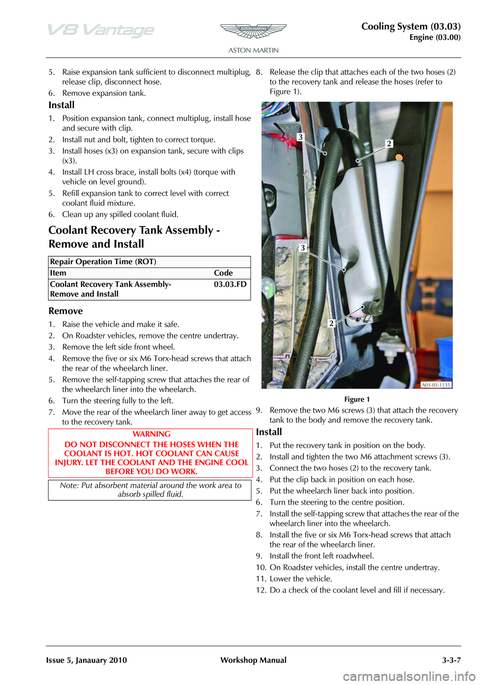
to the recovery tank. 8. Release the clip that attaches each of the two hoses (2)
to the recovery tank and release the hoses (refer to
Figure 1).
Figure 1
9. Remove the two M6 screws (3) that attach the recovery tank to the body and remove the recovery tank.
Install
1. Put the recovery tank in position on the body.
2. Install and tighten the two M6 attachment screws (3).
3. Connect the two hoses (2) to the recovery tank.
4. Put the clip back in position on each hose.
5. Put the wheelarch liner back into position.
6. Turn the steering to the centre position.
7. Install the self-tapping screw that attaches the rear of the wheelarch liner into the wheelarch.
8. Install the five or six M6 Torx-head screws that attach the rear of the wheelarch liner.
9. Install the front left roadwheel.
10. On Roadster vehicles, install the centre undertray.
11. Lower the vehicle.
12. Do a check of the coolant level and fill if necessary.
Repair Operation Time (ROT)
Page 327 of 947
Valve Train (03.09)
Engine (03.00)
Issue 5, January 2010 Workshop Manual 3-9-1
Engine (03.00)
Valve Train (03.09)
Specifications
Maintenance
Left Side Timing Chain Arm Assembly -
Remove and Install
Remove
1. Remove the engine timing cover. (03.10.AF - Engine Timing Cover). 2. Remove the two screws that attach the special tool to
the engine.
Figure 1
3. Remove the special tool from the flywheel.
Figure 2
4. Turn the crankshaft clockwise until the machined flat areas on the camshafts are parallel to the face of the
cylinder head.
Figure 3
Torque Figures
DescriptionNmlb/ft
Front Lifting Eye Attachment operated
(M12) 25-35 18.5-
26
Camshaft Caps (M6) all to: 5 3.7
then to: 9-11 6.5-8.1
Secondary Chain Tensioner (M6) 9-13 6.5-8.1
Primary Chain Guide (M6) 9-13 6.5-8.1
Primary Chain Tensioner Blade Pivot 9-13 6.5-8.1
Primary Chain Tensioner 9-13 6.5-8.1
Bush Carrier (“A” Bank) (M8) 19-23 14-17
Bush Carrier (“B” Bank) (M8) 19-23 14-17
(M6) 9-13 6.5-8.1
Exhaust Cam Sprocket Bolt
then 90° more, ±5° 20 14.8
Front Cover:
Bolts 1 to 7, 9 to 18 and 20 to 27
Bolts 8 and 9 11-13
9-116.5-8.1
6.5-8.1
Repair Operation Time (ROT)
Page 339 of 947
Valve Train (03.09)
Engine (03.00)
Issue 5, January 2010 Workshop Manual 3-9-13
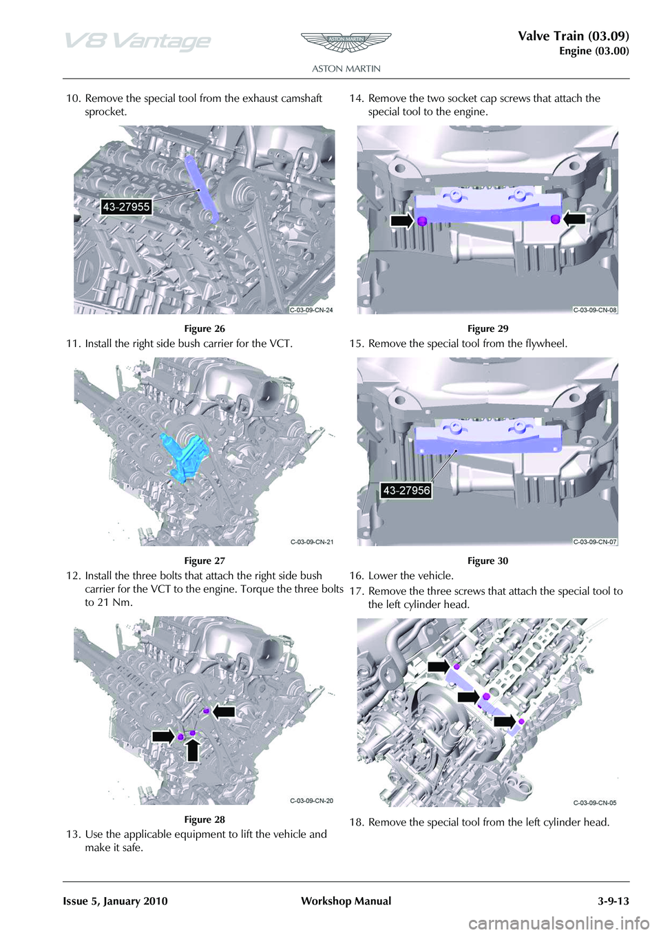
10. Remove the special tool from the exhaust camshaft sprocket.
Figure 26
11. Install the right side bush carrier for the VCT.
Figure 27
12. Install the three bolts that attach the right side bush carrier for the VCT to the engine. Torque the three bolts
to 21 Nm.
Figure 28
13. Use the applicable equipment to lift the vehicle and make it safe. 14. Remove the two socket cap screws that attach the
special tool to the engine.
Figure 29
15. Remove the special tool from the flywheel.
Figure 30
16. Lower the vehicle.
17. Remove the three screws that attach the special tool to the left cylinder head.
18. Remove the special tool from the left cylinder head.
Page 367 of 947
Engine Sealing (03.10)
Engine (03.00)
Issue 5, Janauary 2010 Workshop Manual 3-10-9
8. Install the right exhaust camshaft.
9. Install the five bearing caps in their correct positions.
10. Install the ten bolts and torque tighten them in the sequence specified.
11. Install the Torx bolt that attaches the sprocket to the camshaft.
12. Rotate the camshaft and use feeler gauges to do a check of each valve clearance .
13. Do the procedure again an d install the right intake
camshaft.
14. Remove the Torx bolt that attaches the sprocket.
15. Rotate the right intake and exhaust camshafts until the timing flats on each camshaft face up.
16. Install tool (303-530) onto the right cylinder head to hold the camshafts. Install and tighten the three bolts.
17. Install a new left cylinder he ad gasket. Make sure that it
is correctly engaged on the dowels.
18. With the aid of one more person, install the left cylinder head. Make sure that it is correctly engaged on the
dowels.
19. Install and torque the 12 cylinder head bolts in the correct sequence.
20. Lubricate the left exhaust camshaft journals, camshaft lobes, bearing surfaces on the cylinder head and the
bearing caps with clean engine oil.
21. Install left exhaust camshaft.
22. Install the five bearing caps in their correct positions.
23. Install the ten bolts and torque in the sequence specified.
24. Install the Torx bolt that attaches the sprocket to the left exhaust camshaft.
25. Rotate the left exhaust cam shaft as necessary and use
feeler guages to do a check of each valve clearance.
26. Remove the Torx bolt that attaches the sprocket.
27. Install the left intake camshaft (refer to Workshop Manual procedure 03.09.AV Camshaft - Intake - LH -
Renew).
28. Install the timing chain tensioning tool (303-532) into the right exhaust camshaft sprocket.
29. Apply a force to the tool (303-532) in a counterclockwise direction to hold the sprocket and
torque the right sprocket Torx bolts.
30. Remove the special tool.
31. Connect the electrical conne ctors to the left and right
camshaft timing sensors.
32. Connect the electrical connector to each of the two left and two right knock sensors. 33. Install SAI pump and bracket assembly (refer to
Workshop Manual procedure 03.08.DB Pump and
Bracket Assembly - Secondary Air Injection - Renew).
34. Clean the left exhaust manifold.
35. Install a new gasket for the left exhaust manifold .
36. Install the left exhaust manifold.
37. Install and torque tighten the eight nuts.
38. Install the left front wheel arch liner (refer to Workshop
Manual procedure 01.02.FB Wheel Arch Liner - Front -
LH - Renew).
39. Install the right exhaust manifold (refer to Workshop Manual procedure 09.00.CC Gasket - Exhaust Manifold
- right - Renew).
Right Side Cam Cover - Remove and
Install
Removal
1. Disconnect the battery earth cable.
2. Remove the front crush brace. (Refer to procedure
01.01.LC - Front Crush Brace)
3. Remove the right side fr ont crush bar for the body
reinforcement. (Refer to procedure 01.01.AB - Right
Side Front Crush Bar for the Body Reinforcement)
4. Remove the breather pipe from the cam cover.
5. Install applicable caps to seal the open ports.
6. Remove the ignition coil cover.
7. Disconnect the electrical connector from each of the four ignition coils.
8. Disconnect the electrical connector from the Variable Valve Timing (VVT) solenoid.
9. Release the fir tree clip that attaches the wiring harness for the ignition coils.
10. Move the wiring harness for the ignition coils away.
11. Release the wiring harness for the injectors from the mounts.
12. Cut and remove the three cable ties that attach the rear of the wiring harness for the injectors.
13. Remove the screw that attaches the purge pipe P-clip to the cam cover.
14. Move the purge-pipe P-clip away.
15. Release the purge pipe and heater pipe from the two clips on the wiring harness bracket.
16. Remove the two nuts and two screws that attach the front bracket for the wiring harness.
17. Remove the three screws that attach the rear bracket for
the wiring harness.
18. Remove the rear bracket for the wiring harness.
19. Remove the front bracket for the wiring harness.
WA R N I N G
DO NOT GET USED ENGINE OIL ON YOUR SKIN. USED ENGINE OIL CAN BE HARMFUL.
Caution
Gradually tighten one bolt and then the next to correctly
install the camshaft bearing ca ps in the step that follows.
Repair Operation Time (ROT)
Page 373 of 947
Power Conversion (03.11)
Engine (03.00)
May 2007 Workshop Manual 3-11-1
Engine (03.00)
Power Conversion (03.11)
Maintenance
Connecting Rod Bearing-Renew (Engine
Set)
Removal
1. Remove engine oil sump (see Workshop Manual
procedure 03.02.BN Pan - Oil Sump - Remove and Re-
seal).
2. Remove spark plugs (see Workshop Manual procedure 03.07.DB Spark Plugs - Engine Set - Renew).
3. Remove bolts (x8) securing windage tray to engine bedplate, remove windage tray.
4. Mark bearing caps and connecting rods for correct installation.
5. Rotate crankshaft clockwise to access number 1 cylinder connecting rod bolts.
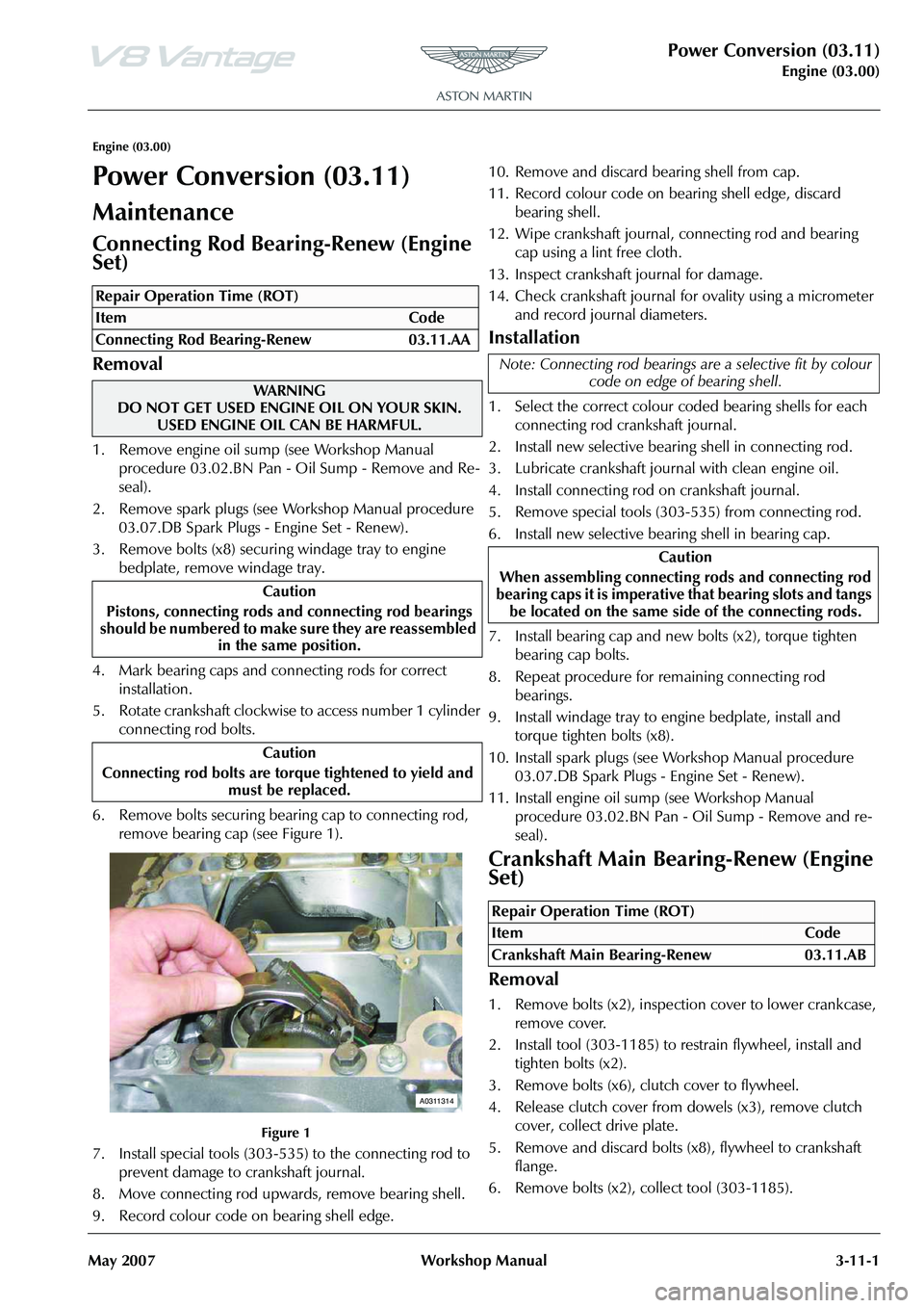
6. Remove bolts securing bearing cap to connecting rod, remove bearing cap (see Figure 1).
Figure 1
7. Install special tools (303-535) to the connecting rod to prevent damage to crankshaft journal.
8. Move connecting rod upwards, remove bearing shell.
9. Record colour code on bearing shell edge. 10. Remove and discard bearing shell from cap.
11. Record colour code on bearing shell edge, discard
bearing shell.
12. Wipe crankshaft journal, connecting rod and bearing cap using a lint free cloth.
13. Inspect crankshaft journal for damage.
14. Check crankshaft journal for ovality using a micrometer and record journal diameters.
Installation
1. Select the correct colour coded bearing shells for each connecting rod crankshaft journal.
2. Install new selective bearing shell in connecting rod.
3. Lubricate crankshaft journal with clean engine oil.
4. Install connecting rod on crankshaft journal.
5. Remove special tools (303-535) from connecting rod.
6. Install new selective bearing shell in bearing cap.
7. Install bearing cap and new bolts (x2), torque tighten bearing cap bolts.
8. Repeat procedure for remaining connecting rod bearings.
9. Install windage tray to engine bedplate, install and torque tighten bolts (x8).
10. Install spark plugs (see Workshop Manual procedure 03.07.DB Spark Plugs - Engine Set - Renew).
11. Install engine oil sump (see Workshop Manual
procedure 03.02.BN Pan - Oil Sump - Remove and re-
seal).
Crankshaft Main Bearing-Renew (Engine
Set)
Removal
1. Remove bolts (x2), inspection cover to lower crankcase, remove cover.
2. Install tool (303-1185) to restrain flywheel, install and tighten bolts (x2).
3. Remove bolts (x6), clutch cover to flywheel.
4. Release clutch cover from dowels (x3), remove clutch cover, collect drive plate.
5. Remove and discard bolts (x8), flywheel to crankshaft flange.
6. Remove bolts (x2), collect tool (303-1185).
Repair Operation Time (ROT)
WA R N I N G
DO NOT GET USED ENGINE OIL ON YOUR SKIN. USED ENGINE OIL CAN BE HARMFUL.
Caution
Pistons, connecting rods an d connecting rod bearings
should be numbered to make sure they are reassembled
in the same position.
Caution
Connecting rod bolts are tor qu
e tightened to yield and
mu st be replaced.
A0311314
Note: Connecting rod bearings ar e a selective fit by colour
code on edge of bearing shell.
Caution
When assembling connecting rods and connecting rod
bearing caps it is imperative that bearing slots and tangs
be located on the same side of the connecting rods.
Repair Operation Time (ROT)
Page 376 of 947
Power Conversion (03.11)
Engine (03.00)3-11-4 Workshop Manual May 2007
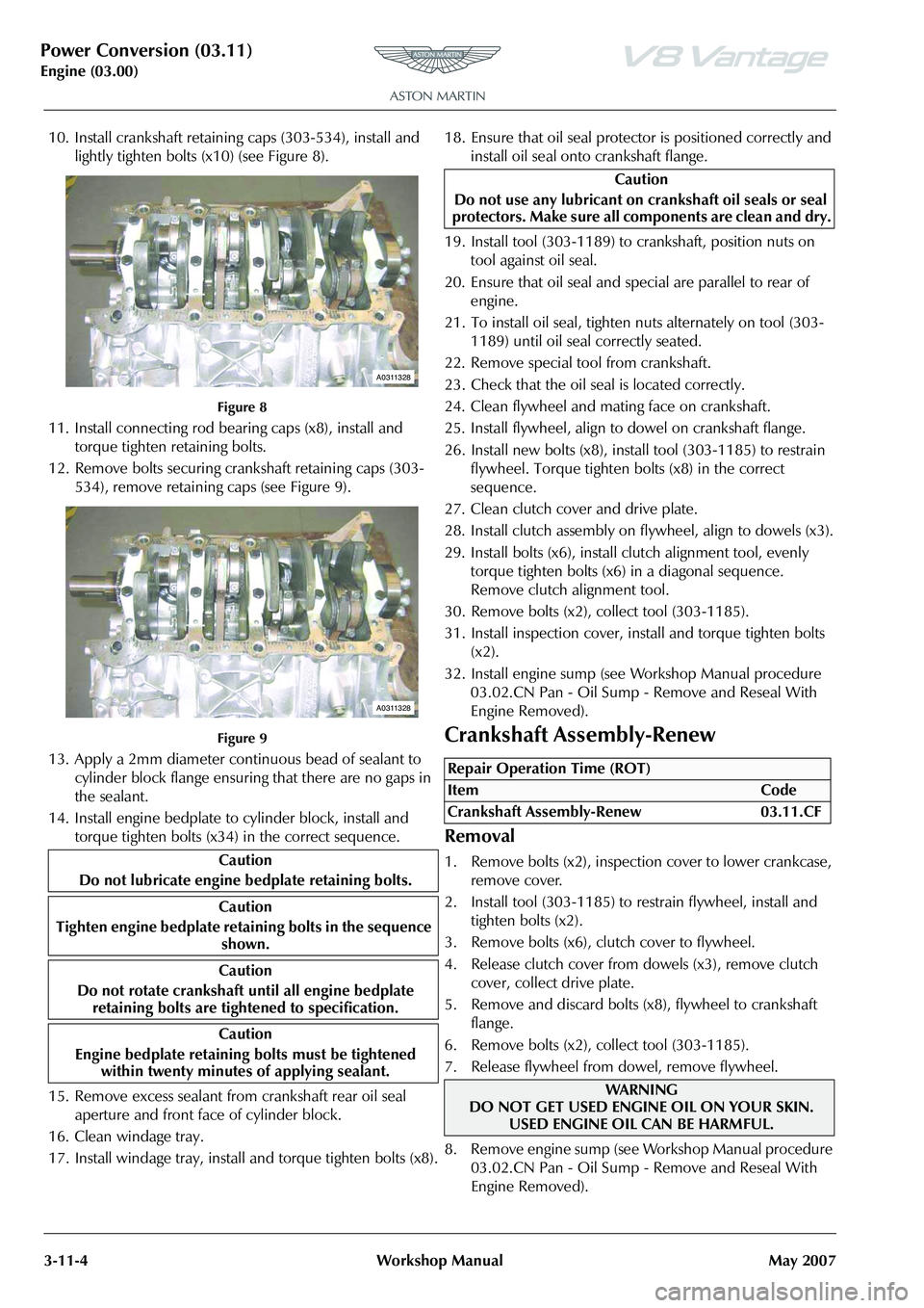
10. Install crankshaft retaining caps (303-534), install and
lightly tighten bolts (x10) (see Figure 8).
Figure 8
11. Install connecting rod bearing caps (x8), install and torque tighten retaining bolts.
12. Remove bolts securing crankshaft retaining caps (303- 534), remove retaining caps (see Figure 9).
Figure 9
13. Apply a 2mm diameter continuous bead of sealant to cylinder block flange ensuring that there are no gaps in
the sealant.
14. Install engine bedplate to cylinder block, install and torque tighten bolts (x34) in the correct sequence.
15. Remove excess sealant from crankshaft rear oil seal
aperture and front face of cylinder block.
16. Clean windage tray.
17. Install windage tray, install and torque tighten bolts (x8). 18. Ensure that oil seal protector is positioned correctly and
install oil seal onto crankshaft flange.
19. Install tool (303-1189) to crankshaft, position nuts on tool against oil seal.
20. Ensure that oil seal and special are parallel to rear of engine.
21. To install oil seal, tighten nuts alternately on tool (303- 1189) until oil seal correctly seated.
22. Remove special tool from crankshaft.
23. Check that the oil se al is located correctly.
24. Clean flywheel and mating face on crankshaft.
25. Install flywheel, align to dowel on crankshaft flange.
26. Install new bolts (x8), install tool (303-1185) to restrain flywheel. Torque tighten bolts (x8) in the correct
sequence.
27. Clean clutch cover and drive plate.
28. Install clutch assembly on flywheel, align to dowels (x3).
29. Install bolts (x6), install clutch alignment tool, evenly torque tighten bolts (x6) in a diagonal sequence.
Remove clutch alignment tool.
30. Remove bolts (x2), collect tool (303-1185).
31. Install inspection cover, install and torque tighten bolts (x2).
32. Install engine sump (see Workshop Manual procedure 03.02.CN Pan - Oil Sump - Remove and Reseal With
Engine Removed).
Crankshaft Assembly-Renew
Removal
1. Remove bolts (x2), inspection cover to lower crankcase, remove cover.
2. Install tool (303-1185) to restrain flywheel, install and tighten bolts (x2).
3. Remove bolts (x6), clutch cover to flywheel.
4. Release clutch cover from dowels (x3), remove clutch cover, collect drive plate.
5. Remove and discard bolts (x8), flywheel to crankshaft flange.
6. Remove bolts (x2), collect tool (303-1185).
7. Release flywheel from dowel, remove flywheel.
8 . R e m o v e e n g i n e s u mp ( s e e Wo r k s h o p M a n u a l p ro c e d u re 03.02.CN Pan - Oil Sump - Remove and Reseal With
Engine Removed).
Caution
Do not lubricate engine bedplate retaining bolts.
Caution
Tighten engine bedplate retaining bolts in the sequence shown.
Caution
Do not rotate crankshaft until all engine bedplate
retaining bolts are tightened to specification.
Caution
Engine bedplate retaining bolts must be tightened
within twenty minutes of applying sealant.
A0311328
A0311328
Caution
Do not use any lubricant on cr ankshaft oil seals or seal
protectors. Make sure all co mponents are clean and dry.
Repair Operation Time (ROT)
ItemCode
Crankshaft Assembly-Renew 03.11.CF
WAR NI NG
DO NOT GET USED ENGINE OIL ON YOUR SKIN.
USED ENGINE OIL CAN BE HARMFUL.
Page 379 of 947
Power Conversion (03.11)
Engine (03.00)
May 2007 Workshop Manual 3-11-7
27. Clean flywheel and mating face on crankshaft.
28. Install flywheel, align to dowel on crankshaft flange.
29. Install new bolts (x8), install tool (303-1185) to restrain
flywheel. Torque tighten bolts (x8) in the correct
sequence.
30. Clean clutch cover and drive plate.
31. Install clutch assembly on fl ywheel, align to dowels (x3).
32. Install bolts (x6), install clutch alignment tool, evenly torque tighten bolts (x6) in a diagonal sequence.
Remove clutch alignment tool.
33. Remove bolts (x2), collect tool (303-1185).
34. Install inspection cover, install and torque tighten bolts (x2).
35. Install engine sump (see Workshop Manual procedure 03.02.CN Pan - Oil Sump - Remove and Reseal With
Engine Removed).
Piston-Renew (Engine Set)
Removal
1. Remove cylinder head gaskets - engine set (see Workshop Manual procedure 03.01.HW Gasket -
Cylinder Head - Engine Set - Renew With Engine
Removed).
2. Remove crankshaft timing sprocket from crankshaft.
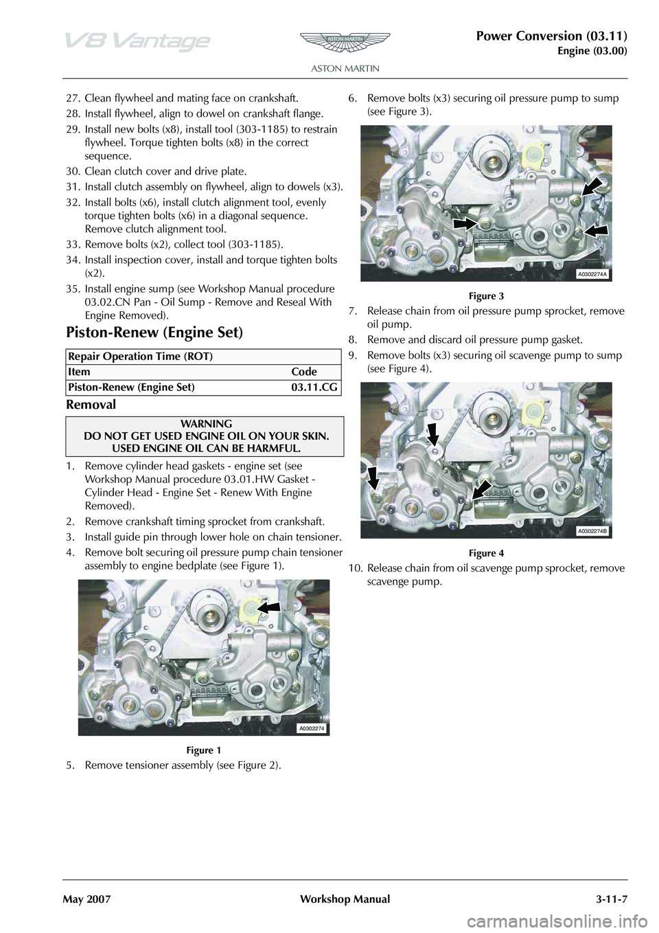
3. Install guide pin through lower hole on chain tensioner.
4. Remove bolt securing oil pr essure pump chain tensioner
assembly to engine bedplate (see Figure 1).
Figure 1
5. Remove tensioner assembly (see Figure 2). 6. Remove bolts (x3) securing oil pressure pump to sump
(see Figure 3).
Figure 3
7. Release chain from oil pressure pump sprocket, remove oil pump.
8. Remove and discard oil pressure pump gasket.
9. Remove bolts (x3) securing oil scavenge pump to sump
(see Figure 4).
Figure 4
10. Release chain from oil scavenge pump sprocket, remove scavenge pump.
Repair Operation Time (ROT)
WA R N I N G
DO NOT GET USED ENGINE OIL ON YOUR SKIN.
USED ENGINE OIL CAN BE HARMFUL.
A0302274
A0302274A
A0302274B
Page 400 of 947
Power Conversion (03.11)
Engine (03.00)3-11-28 Workshop Manual May 2007
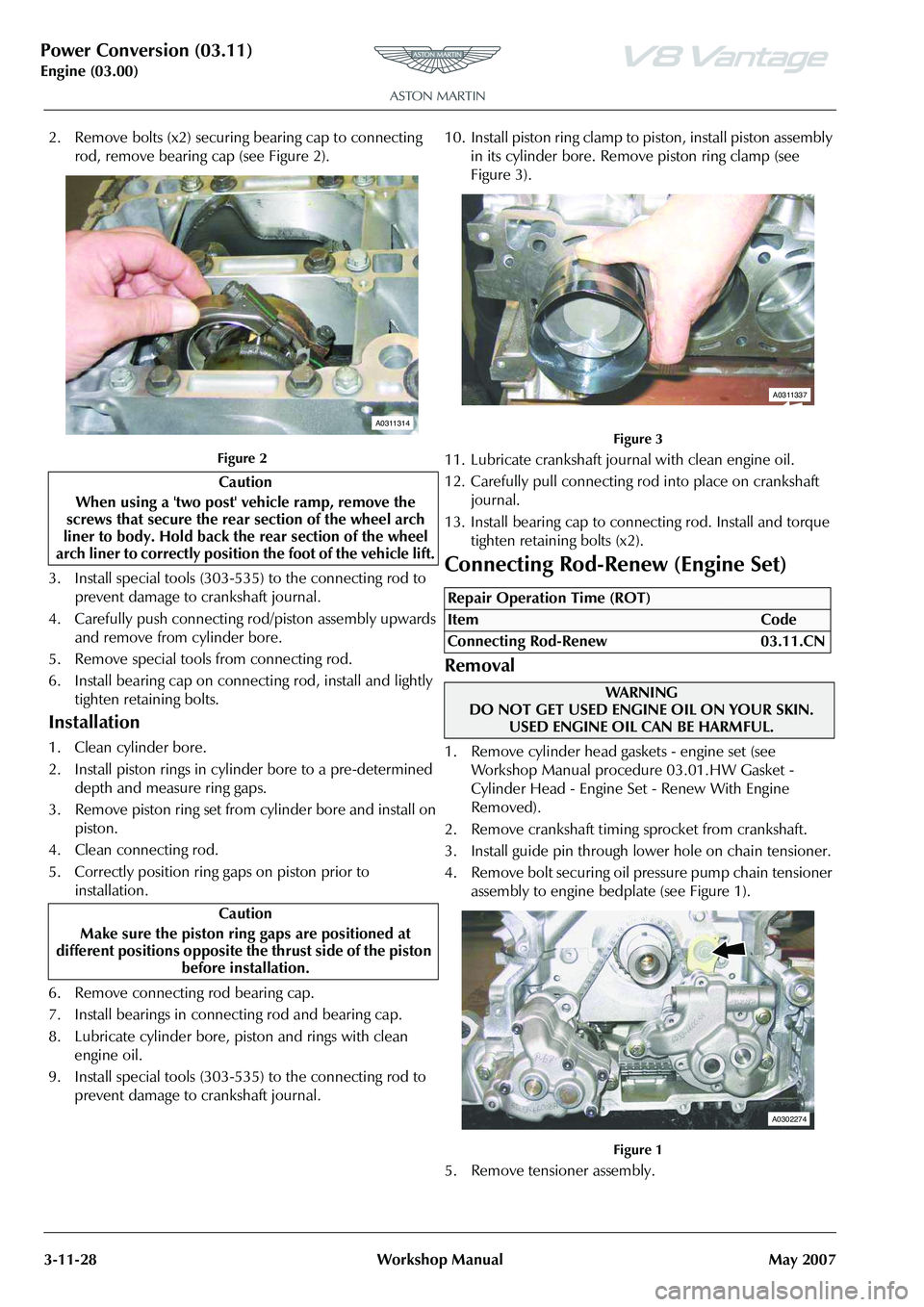
2. Remove bolts (x2) securing bearing cap to connecting
rod, remove bearing cap (see Figure 2).
Figure 2
3. Install special tools (303-535) to the connecting rod to prevent damage to crankshaft journal.
4. Carefully push connecting rod/piston assembly upwards and remove from cylinder bore.
5. Remove special tools from connecting rod.
6. Install bearing cap on connecting rod, install and lightly tighten retaining bolts.
Installation
1. Clean cylinder bore.
2. Install piston rings in cylinder bore to a pre-determined depth and measure ring gaps.
3. Remove piston ring set from cylinder bore and install on piston.
4. Clean connecting rod.
5. Correctly position ring gaps on piston prior to installation.
6. Remove connecting rod bearing cap.
7. Install bearings in connecting rod and bearing cap.
8. Lubricate cylinder bore, pi ston and rings with clean
engine oil.
9. Install special tools (303-535) to the connecting rod to prevent damage to crankshaft journal. 10. Install piston ring clamp to piston, install piston assembly
in its cylinder bore. Remove piston ring clamp (see
Figure 3).
Figure 3
11. Lubricate crankshaft jour nal with clean engine oil.
12. Carefully pull connecting rod into place on crankshaft journal.
13. Install bearing cap to connecting rod. Install and torque tighten retaining bolts (x2).
Connecting Rod-Renew (Engine Set)
Removal
1. Remove cylinder head gaskets - engine set (see Workshop Manual procedure 03.01.HW Gasket -
Cylinder Head - Engine Set - Renew With Engine
Removed).
2. Remove crankshaft timing sprocket from crankshaft.
3. Install guide pin through lower hole on chain tensioner.
4. Remove bolt securing oil pressure pump chain tensioner assembly to engine bedplate (see Figure 1).
Figure 1
5. Remove tensioner assembly.
Caution
When using a 'two post' vehicle ramp, remove the
screws that secure the rear section of the wheel arch
liner to body. Hold back the rear section of the wheel
arch liner to correctly position the foot of the vehicle lift.
Caution
Make sure the piston ring gaps are positioned at
different positions opposite th e thrust side of the piston
before installation.
A0311314
Repair Operation Time (ROT)
ItemCode
Connecting Rod-Renew 03.11.CN
WAR NI NG
DO NOT GET USED ENGINE OIL ON YOUR SKIN.
USED ENGINE OIL CAN BE HARMFUL.
A0311337
A0302274