door lock ASTON MARTIN V8 VANTAGE 2010 Workshop Manual
[x] Cancel search | Manufacturer: ASTON MARTIN, Model Year: 2010, Model line: V8 VANTAGE, Model: ASTON MARTIN V8 VANTAGE 2010Pages: 947, PDF Size: 43.21 MB
Page 14 of 947
1-1-2 Workshop Manual Issue 5, January 2010
RH/LH Seat Switchpack Assembly - Renew...........7-13
Lumbar Pump for the Front Seat (From 08MY)
- Remove and Install.............................................7-13
Lumbar Valve for the Front Seat (From 08MY)
- Remove and Install.............................................7-14
Lumbar Bladder for the Front Seat (From 08MY)
- Remove and Install.............................................7-14
Glass, Frame and Mechanism (01.11) .................. 1-8-1 Description .............................................................8-1 Frameless doors......................................................8-1
Specifications .........................................................8-1
Maintenance ...........................................................8-1 Glass Regulator - Renew .........................................8-1
RH/LH Door Glass - Renew ....................................8-2
Door Glass - Adjust/Reset .......................................8-3
Front Windshield - Renew ......................................8-3
Rear Windshield - Renew .......................................8-4
Quarter Window Glass - Renew .............................8-6
Passenger Window Lift Switch - Renew ..................8-6
Driver Window Lift Switch - Renew........................8-7
Instrument Panel (IP) (01.12)................................ 1-9-1 Specifications ..........................................................9-1
Maintenance ...........................................................9-1 Instrument Panel - Renew ......................................9-1
Airbag Panel and Door Assembly - Renew ..............9-6
Glovebox Assembly - Renew ..................................9-6
Instrument Centre Panel Asse mbly - Renew............9-7
Knee Protector - Renew .........................................9-7
Instrument Panel As sembly - Renew .......................9-7
Cluster Bezel Panel - Renew .................................9-10
Driver Panel Assembly - Renew ............................9-10
Instrument Panel Bezel A ssembly (With Sat. Nav.)
- Renew ...............................................................9-11
Instrument Panel Bezel Assembly
(Without Sat. Nav.) - Renew .................................9-11
Rear Console Panel Assembly - Renew .................9-12
Armrest Pad Assembly - Renew ............................9-13
Console Panel Assembly - Renew .........................9-13
RH/LH Rear Console Pa nel Assembly - Renew
(Roadster Only) ....................................................9-13
Centre Console Panel - Remove and Install
(Coupe Only) .......................................................9-15
Centre Console Panel - Remove and Install
(Roadster Only) ....................................................9-19
RH/LH Lower Quarter Panel Assembly - Renew
(Roadster Only) ....................................................9-29
Handles and Lock Mechanisms (01.14) .............. 1-10-1 Description ...........................................................10-1 Vehicle Key/Remote Transmitter...........................10-1
Central Locking System ........................................10-1
Remote Transmitter ..............................................10-1
Fuel Filler Assembly ..............................................10-1
Boot Emergency Release ....... ...............................10-1
Specifications ........................................................10-2
Maintenance .........................................................10-2 Ignition Cylinder Lock - Re new.............................10-2
RH/LH Front Door Latch As sembly - Renew .........10-2
Bonnet Latch Assembly - Renew...........................10-3
Hood Release Cable Assembly - Renew (Roadster Only) .................................................... 10-3
Bonnet Secondary Latch Asse
mbly - Renew ......... 10-4
Tailgate Latch and Cable Assembly - Renew ......... 10-4
Fuel Filler Actuator Assembly - Renew
(Roadster Only) .................................................... 10-4
Fuel Filler Release Cable - Renew (Roadster Only) 10-5
Fuel Flap Release Switch - Renew ........................ 10-6
RH/LH Tonneau Latch Motor - Renew
(Roadster Only) .................................................... 10-7
RH/LH Tonneau Latch - Renew (Roadster Only) ... 10-7
RH/LH Tonneau Cover Striker Assembly
- Renew (Roadster Only) ...................................... 10-8
Tailgate Latch Assembly-Renew (Roadster Only) ... 10-8
Wipers and Washer System (01.16) ....................1-11-1 Headlamp Washing .............................................. 11-1
Specifications ........................................................ 11-2
Maintenance ......................................................... 11-2 Windscreen Wiper Motor As sembly - Renew ....... 11-2
Wiper Linkage Assembly - Renew ........................ 11-2
Windshield Wash Tube - Renew .......................... 11-2
Windscreen Reservoir and Motor Assembly
- Remove and Install ............................................ 11-3
Low Level Water Sensor - Remove and Install ...... 11-4
Headlamp Wash Motor and Pump Assembly
- Renew ............................................................... 11-5
Headlamp Wash Tube Assembly - Renew ............ 11-5
Washer Fluid Reservoir - Renew........................... 11-6
Convertible Roof and Roof Opening Subsystem
(01.17)..................................................................1-12-1 System Description .............................................. 12-1
Maintenance ......................................................... 12-2 Hood Assembly-Renew ........................................ 12-2
Canopy Cover - Renew ........................................ 12-5
Header Latch Motor - Renew ............................... 12-9
Hydraulic Main Actuator Cy linder - Renew .......... 12-9
Hydraulic Tensrod Cylinder - Renew .................. 12-10
Hydraulic Tonneau Cylinder - Renew................. 12-11
Convertible Top ECU - Renew ........................... 12-13
Hydraulic Pump - Renew ................................... 12-13
Hydraulic Lock Valve - Renew............................ 12-16
RH/LH Front Cantrail Seal - Spare Part
- Renew ............................................................. 12-18
RH/LH Front Cantrail Seal Spare Part Kit
- Renew ............................................................. 12-18
RH/LH Middle Cantrail Seal Spare Part
- Renew ............................................................. 12-18
RH/LH Middle Cantrail Seal Spare Part Kit
- Renew ............................................................. 12-19
Rear Seal Spare Part Assembly Kit - Renew ......... 12-20
LH Fully Automatic Latching Kit - Renew............ 12-21
RH Fully Automatic Latching Kit - Renew ........... 12-22
Convertible Roof Hydraulic Pump
- Check Fluid Level ............................................ 12-23
Cantrail Cover Trim - Renew .............................. 12-25
B-Post Trim Cover - Renew ................................ 12-25
Tonneau Cover - Renew .................................... 12-27
LH Front Main Hydraulic Cylinder Pipe
- Renew ............................................................. 12-29
LH Rear Main Hydraulic Cylinder Pipe
Page 15 of 947

Issue 5, January 2010 Workshop Manual 1-1-3
- Renew ............................................................. 12-33
RH Front Main Hydraulic Cylinder Pipe
- Renew ............................................................. 12-37
RH Rear Main Hydraulic Cylinder Pipe
- Renew ............................................................. 12-40
LH Front Hydraulic Cylinder Pipe - Renew........ 12-43
LH Rear Hydraulic Cylinder Pipe - Renew.......... 12-46
RH Front Hydraulic Cylinder Pipe - Renew ........ 12-50
RH Rear Hydraulic Cylinder Pipe - Renew ......... 12-53
RH/LH Rear Hydraulic Tonneau Cylinder Pipe
- Renew ............................................................. 12-56
LH/RH Front Hydraulic Tonneau Cylinder Pipe
- Renew ............................................................. 12-60
Hydraulic Cylinder Valve to Pump Pipe
- Renew ............................................................. 12-63
Wind Deflector - Renew .................................... 12-66
Tonneau Well Liner - Renew . ............................ 12-67
RH/LH Flex Shaft - Renew ................................. 12-69
Bumpers (01.19) .................................................. 1-13-1 Front Bumper ....................................................... 13-1
Rear Bumper......................................................... 13-1
Specifications........................................................ 13-2
Maintenance ......................................................... 13-2Front Bumper Cover - Renew .............................. 13-2
Rear Bumper Cover - Renew................................ 13-3
Restraining Devices (01.20)................................. 1-14-1 Seat Belts .............................................................. 14-1Emergency Locking Retractor (ELR) ...................... 14-2
Airbag System ....................................................... 14-3
Maintenance ......................................................... 14-4 Driver’s Airbag Module - Renew .......................... 14-4
LH Front Seat Belt - Renew .................................. 14-4
RH Front Seat Belt - Renew.................................. 14-5
Passenger Airbag - Renew .................................... 14-6
ARS Side Impact Sensor Assembly - B Pillar
- Renew ............................................................... 14-6
Side Impact Door ARS Sensor Assembly
- Renew ............................................................... 14-6
Front Impact Sensor Assembly - Renew ................ 14-7
Occupant Restraint Control Module Assembly
- Renew ............................................................... 14-7
RH/LH Roll Over Protection System - Renew ....... 14-8
Page 30 of 947

Body Closures (01.03)
Body System (01.00)1-3-4 Workshop Manual May 2007
19. Remove nuts (x4) and Torx screws (x3) securing door glass regulator to door frame (see Figure 6).
20. Carefully remove regulator mechanism through the larger door frame aperture.
21. Remove door mirror rubber cheater (see Figure 7).
22. Disconnect door mirror mult iplug, release harness fir
tree clips (x2) and self adhe sive clip (see Figure 8). 23. Remove Torx Bolts (x3) and screw from door glass
channel. Remove door mirror assembly.
24. Remove aperture seal from inner door frame.
25. Remove fir tree trim pins (x3), release/remove rear
weatherstrip from door frame/glass channel.
26. Disconnect door latch multiplug.
27. Release inner and outer cable from external door handle (see Figure 9).
28. Remove nuts (x3) securi ng external door handle,
remove door handle (see Figure 10).
29. Loosen upper nut, remove lower nut securing keylock mechanism to door frame.
Figure 6
Figure 7
Figure 8
A011139A
A0108144
A0108143
Figure 9
Figure 10
A0114138A
A0114138
Page 31 of 947
Body Closures (01.03)
Body System (01.00)
May 2007 Workshop Manual 1-3-5
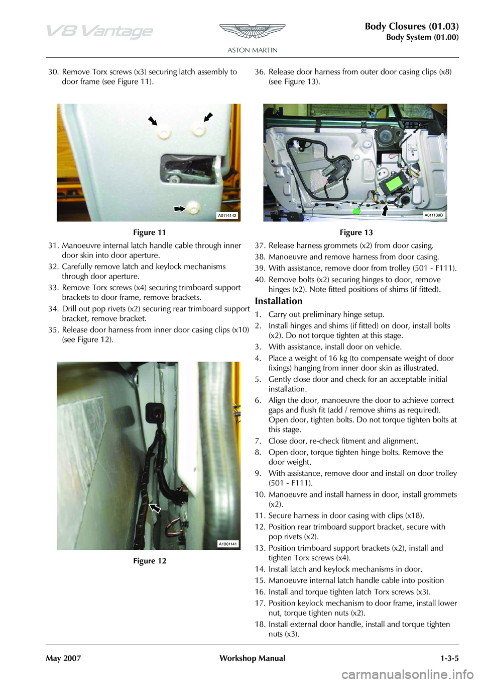
30. Remove Torx screws (x3) securing latch assembly to
door frame (see Figure 11).
31. Manoeuvre internal latch handle cable through inner door skin into door aperture.
32. Carefully remove latch and keylock mechanisms through door aperture.
33. Remove Torx screws (x4) securing trimboard support
brackets to door frame, remove brackets.
34. Drill out pop rivets (x2) securing rear trimboard support bracket, remove bracket.
35. Release door harness from inner door casing clips (x10) (see Figure 12). 36. Release door harness from outer door casing clips (x8)
(see Figure 13).
37. Release harness grommets (x2) from door casing.
38. Manoeuvre and remove ha rness from door casing.
39. With assistance, remove door from trolley (501 - F111).
40. Remove bolts (x2) securing hinges to door, remove
hinges (x2). Note fitted posi tions of shims (if fitted).
Installation
1. Carry out preliminary hinge setup.
2. Install hinges and shims (if fitted) on door, install bolts
(x2). Do not torque tighten at this stage.
3. With assistance, install door on vehicle.
4. Place a weight of 16 kg (to compensate weight of door fixings) hanging from inner door skin as illustrated.
5. Gently close door and check for an acceptable initial installation.
6. Align the door, manoeuvre the door to achieve correct gaps and flush fit (add / remove shims as required).
Open door, tighten bolts. Do not torque tighten bolts at
this stage.
7. Close door, re-check fitment and alignment.
8. Open door, torque tighten hinge bolts. Remove the door weight.
9. With assistance, remove door and install on door trolley
(501 - F111).
10. Manoeuvre and install harness in door, install grommets (x2).
11. Secure harness in door casing with clips (x18).
12. Position rear trimboard support bracket, secure with pop rivets (x2).
13. Position trimboard support brackets (x2), install and
tighten Torx screws (x4).
14. Install latch and keylock mechanisms in door.
15. Manoeuvre internal latch handle cable into position
16. Install and torque tighten latch Torx screws (x3).
17. Position keylock mechanism to door frame, install lower nut, torque tighten nuts (x2).
18. Install external door handle, install and torque tighten nuts (x3).
Figure 11
Figure 12
A0114142
A1801141
Figure 13
A011139B
Page 101 of 947

Instrument Panel (IP) (01.12)
Body System (01.00)
Issue 5, January 2010 Workshop Manual 1-9-13
Installation
1. Position rear console panel, install and tighten nuts (x3) and screws (x4).
2. Install screws (x2) ashtray console panel to floor.
3. Install centre arm rest.
4. Install support rail, install and tighten screws (x5) and bolt.
5. Install stowage compartment door.
6. Battery isolation switch ‘ON’.
Armrest Pad Assembly - Renew
Removal
1. Battery isolation switch ‘OFF’.
2. Remove stowage compartment door.
3. Remove bolt (x1) and screws (x5) support rail to body.
4. Remove screw (x1) centre arm rest to rear console panel assembly.
5. Release and remove arm rest
Installation
1. Install arm rest assembly.
2. Install rear support rail
3. Install stowage compartment door.
4. Battery isolation switch ‘ON’.
Console Panel Assembly - Renew
Removal
1. Battery isolation switch ‘OFF’.
2. Remove stowage compartment door.
3. Remove bolt (x1) and screws (x5) support rail to body.
4. Remove screw (x1) centre arm rest to rear console panel assembly.
5. Release and remove arm rest
6. Release gear lever gaiter.
7. Remove screws (x2) ashtra y console panel assembly to
floor.
8. Release switch panel and disconnect multiplugs (x6) and Lucar connectors (x2).
9. Remove switch panel.
10. Remove boot release and central locking switch.
11. Remove switches below ashtray (x4)
12. Remove Ashtray from panel assembly. (Allen screws x4)
Installation
1. Install ashtray to panel 2. Install switches (x4)
3. Install switch panel screws (x2).
4. Install boot release and central locking switch to panel
assembly console.
5. Position switch panel and connect multiplugs and Lucar connectors.
6. Install gear lever gaiter.
7. Install arm rest assembly.
8. Install rear support rail
9. Install stowage compartment door.
10. Battery isolation switch ’ON’.
RH/LH Rear Console Panel Assembly -
Renew (Roadster Only)
Removal
1. Remove panel assembly ce ntre (see Workshop Manual
procedure 01.05.FR/01.05.FS Panel Assembly - Centre -
Rear Bulkhead - LH/RH - Renew).
2. Remove screw (x1) trim to body lower (see Figure 1).
Repair Operation Time (ROT)
Repair Operation Time (ROT)
Repair Operation Time (ROT)
Page 121 of 947
Handles and Lock Mechanisms (01.14)
Body System (01.00)
May 2007 Workshop Manual 1-10-1
Body System (01.00)
Handles and Lock Mechanisms (01.14)
Description
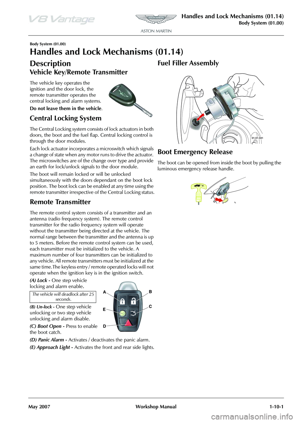
The vehicle key operates the
ignition and the door lock, the
remote transmitter operates the
central locking and alarm systems.
Do not leave them in the vehicle .
Central Locking System
The Central Locking system consists of lock actuators in both
doors, the boot and the fuel flap. Central locking control is
through the door modules.
Each lock actuator incorporates a microswitch which signals
a change of state when any motor runs to drive the actuator.
The microswitches are of the change over type and provide
an earth for lock/unlock signals to the door module.
The boot will remain locked or will be unlocked
simultaneously with the doors dependant on the boot lock
position. The boot lock can be enabled at any time using the
remote transmitter irrespective of the Central Locking status.
Remote Transmitter
The remote control system consists of a transmitter and an
antenna (radio frequency system). The remote control
transmitter for the radio frequency system will operate
without the transmitter being directed at the vehicle. The
normal range between the transmitter and the antenna is up
to 5 meters. Before the remote control system can be used,
each transmitter must be initialized to the vehicle. A
maximum number of four transmitters can be initialized to
any vehicle. All remote transmitters must be initialized at the
same time.The keyless entry / remote operated locks will not
operate when the ignition key is in the ignition switch.
(A) Lock - One step vehicle
locking and alarm enable
.
(B) Un-lock - One step vehicle
unlocking or two step vehicle
unlocking and alarm disable.
(C) Boot Open - Press to enable
the boot catch.
(D) Panic Alarm - Activates / deactivates the panic alarm.
(E) Approach Light - Activates the front and rear side lights.
Fuel Filler Assembly
Boot Emergency Release
The boot can be opened from in side the boot by pulling the
luminous emergency release handle.
The vehicle will deadlock after 25 seconds.
Page 122 of 947

Handles and Lock Mechanisms (01.14)
Body System (01.00)1-10-2 Workshop Manual May 2007
Specifications
Maintenance
Ignition Cylinder Lock - Renew
Removal
1. Remove steering column shroud (see Workshop Manual procedure 11.04.DB Shroud Assembly - Upper and
Lower - Steering Column - Renew).
2. Insert ignition key into steering lock and turn to position 2 (see Figure 1).
3. Push release button down (through hole). 4. Retract barrel by pulling outwards (gently rotate from
side to side) with key (see Figure 2).
5. Remove key from barrel.
Installation
1. Install key to barrel.
2. Install barrel into steering lock housing until button locates properly.
3. Install steering column shroud (see Workshop Manual procedure 11.04.DB Shroud Assembly - Upper and
Lower - Steering Column - Renew).
RH/LH Front Door Latch Assembly -
Renew
Removal
1. Remove glass regulator (see Workshop Manual procedure 01.11.DA/01.11.1DB Regulator - Door Glass
- LH/RH - Renew).
2. Remove aperture seal from inside door.
3. Remove rear rubber cheater panel, fir tree trim pins (x3), and inner glass seal.
4. Disconnect latch mechanism multiplug.
5. Disconnect exterior door handle inner and outer cable.
6. Remove nuts (x3) securing exterior door handle, remove
handle.
7. Loosen upper nut and remo ve lower nut securing key
lock mechanism.
Torque Figures
DescriptionNm
Door handle 5
Latch 9
Repair Operation Time
ItemCode
Ignition Cylinder Lock-Renew 01.14.AD
Figure 1
A0114311
Figure 2
Repair Operation Time (ROT)
ItemCode
Front Door Latch Assembly RH01.14.CE
Front Door Latch Assembly LH01.14.CF
A0114312
Page 123 of 947
Handles and Lock Mechanisms (01.14)
Body System (01.00)
May 2007 Workshop Manual 1-10-3
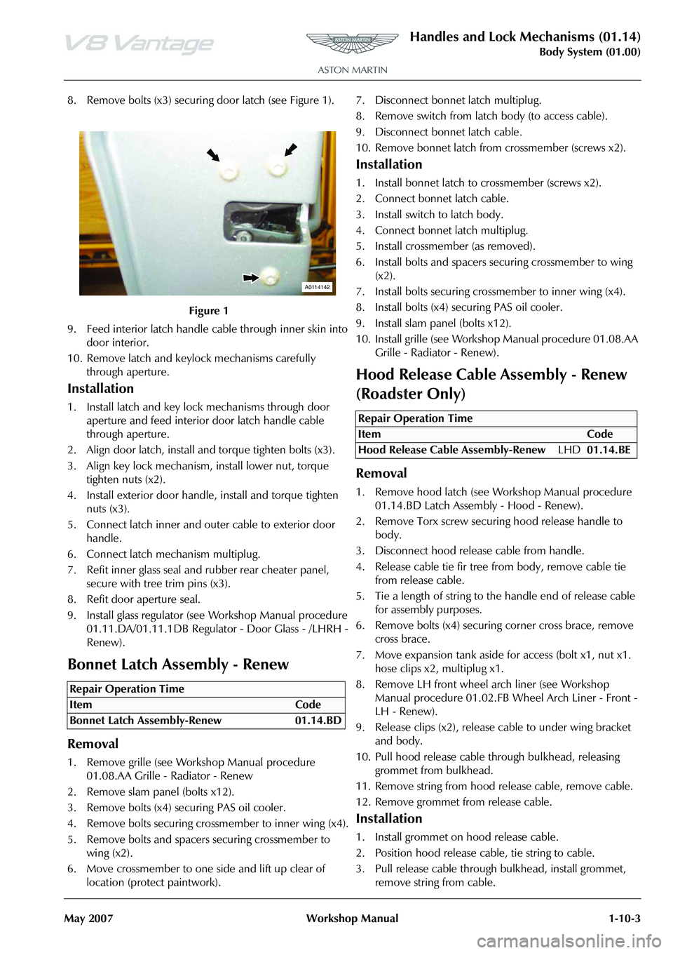
8. Remove bolts (x3) securing door latch (see Figure 1).
9. Feed interior latch handle cable through inner skin into door interior.
10. Remove latch and keylock mechanisms carefully through aperture.
Installation
1. Install latch and key lock mechanisms through door aperture and feed interior door latch handle cable
through aperture.
2. Align door latch, install and torque tighten bolts (x3).
3. Align key lock mechanism, install lower nut, torque tighten nuts (x2).
4. Install exterior door handle, install and torque tighten nuts (x3).
5. Connect latch inner and outer cable to exterior door handle.
6. Connect latch mechanism multiplug.
7. Refit inner glass seal and rubber rear cheater panel, secure with tree trim pins (x3).
8. Refit door aperture seal.
9. Install glass regulator (see Workshop Manual procedure 01.11.DA/01.11.1DB Regulato r - Door Glass - /LHRH -
Renew).
Bonnet Latch Assembly - Renew
Removal
1. Remove grille (see Workshop Manual procedure 01.08.AA Grille - Radiator - Renew
2. Remove slam panel (bolts x12).
3. Remove bolts (x4) securing PAS oil cooler.
4. Remove bolts securing crossmember to inner wing (x4).
5. Remove bolts and spacers securing crossmember to wing (x2).
6. Move crossmember to one side and lift up clear of location (protect paintwork). 7. Disconnect bonnet latch multiplug.
8. Remove switch from latch body (to access cable).
9. Disconnect bonnet latch cable.
10. Remove bonnet latch from
crossmember (screws x2).
Installation
1. Install bonnet latch to crossmember (screws x2).
2. Connect bonnet latch cable.
3. Install switch to latch body.
4. Connect bonnet latch multiplug.
5. Install crossmember (as removed).
6. Install bolts and spacers securing crossmember to wing
(x2).
7. Install bolts securing cros smember to inner wing (x4).
8. Install bolts (x4) securing PAS oil cooler.
9. Install slam panel (bolts x12).
10. Install grille (see Workshop Manual procedure 01.08.AA
Grille - Radiator - Renew).
Hood Release Cable Assembly - Renew
(Roadster Only)
Removal
1. Remove hood latch (see Wo rkshop Manual procedure
01.14.BD Latch Assembly - Hood - Renew).
2. Remove Torx screw securi ng hood release handle to
body.
3. Disconnect hood releas e cable from handle.
4. Release cable tie fir tree fr om body, remove cable tie
from release cable.
5. Tie a length of string to the handle end of release cable for assembly purposes.
6. Remove bolts (x4) securing corner cross brace, remove
cross brace.
7. Move expansion tank aside for access (bolt x1, nut x1. hose clips x2, multiplug x1.
8. Remove LH front wheel arch liner (see Workshop Manual procedure 01.02.FB Wheel Arch Liner - Front -
LH - Renew).
9. Release clips (x2), release cable to under wing bracket and body.
10. Pull hood release cable th rough bulkhead, releasing
grommet from bulkhead.
11. Remove string from hood release cable, remove cable.
12. Remove grommet from release cable.
Installation
1. Install grommet on hood release cable.
2. Position hood release cable, tie string to cable.
3. Pull release cable through bulkhead, install grommet, remove string from cable.
Figure 1
Repair Operation Time
ItemCode
Bonnet Latch Assembly-Renew 01.14.BD
A0114142
Repair Operation Time
ItemCode
Hood Release Cable Assembly-Renew LHD01.14.BE
Page 657 of 947
Battery System (14.01)
Power Supply (14.00)14-1-2 Workshop Manual May 2007
Power Supply (14.00)
Battery System (14.01)
Description
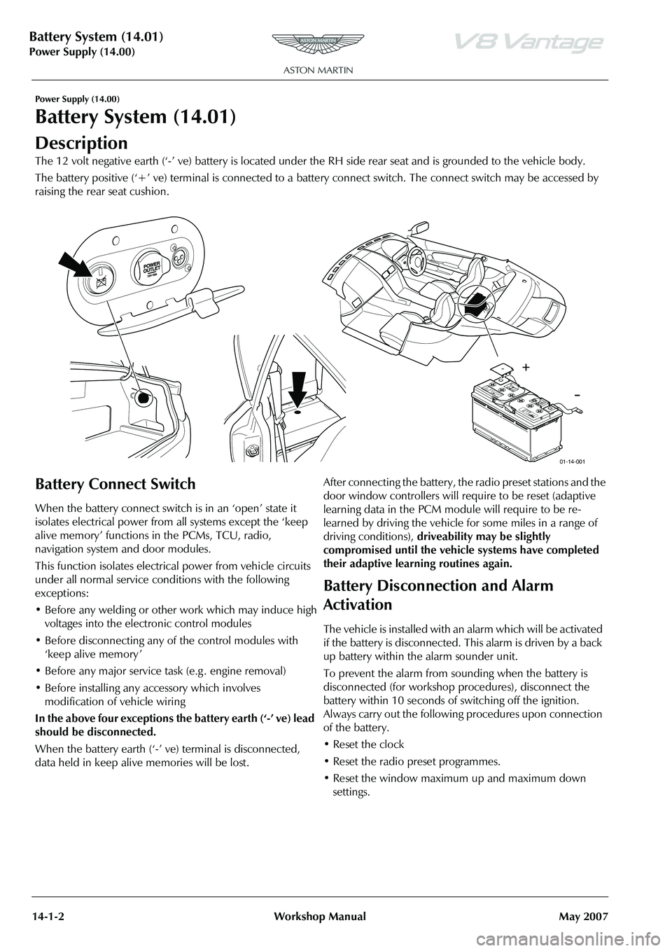
The 12 volt negative earth (‘-’ ve) battery is located under the RH side rear seat and is grounded to the vehicle body.
The battery positive (‘+’ ve) terminal is connected to a battery connect switch. The connect switch may be accessed by
raising the rear seat cushion.
Battery Connect Switch
When the battery connect switch is in an ‘open’ state it
isolates electrical power from all systems except the ‘keep
alive memory’ functions in the PCMs, TCU, radio,
navigation system and door modules.
This function isolates electri cal power from vehicle circuits
under all normal service conditions with the following
exceptions:
• Before any welding or other work which may induce high voltages into the electronic control modules
• Before disconnecting any of the control modules with ‘keep alive memory ’
• Before any major service task (e.g . engine removal)
• Before installing any accessory which involves modification of vehicle wiring
In the above four exceptions the battery earth (‘-’ ve) lead
should be disconnected.
When the battery earth (‘-’ ve) terminal is disconnected,
data held in keep alive memories will be lost. After connecting the battery, the radio preset stations and the
door window controllers will require to be reset (adaptive
learning data in the PCM module will require to be re-
learned by driving the vehicle for some miles in a range of
driving conditions),
driveability may be slightly
compromised until the vehicle systems have completed
their adaptive learning routines again.
Battery Disconnection and Alarm
Activation
The vehicle is installed with an alarm which will be activated
if the battery is disconnected. This alarm is driven by a back
up battery within the alarm sounder unit.
To prevent the alarm from so unding when the battery is
disconnected (for workshop procedures), disconnect the
battery within 10 seconds of switching off the ignition.
Always carry out the following procedures upon connection
of the battery.
• Reset the clock
• Reset the radio preset programmes.
• Reset the window maximum up and maximum down settings.
Pb
A
ST O
N
M A
R
TI
N
S H I
E L
D
E YE
S
NO S
U L
F U R
IC
A C I
DF
LU
SH
E
YES
I M
MED IA T
E LY
W IT
H
W A
T
E R
G ET
M ED
IC
AL
H ELP
F A
STSPA
R
KS
F LA
M
ES
S M
OKIN
GD AN G ER / P
OIS
ONEXP L
O S
IV E
G ASE
SC AN
C A
U SE C
A
N C A
U SE
B L
IN DN
ESS
O R
S E
V ER E
B U RNS
B
LI
NDN
ES S
O R
IN JU R
YK EEP
O UT
O F T
HE R
EA C
H O F C H
IL DR
EN D O N
OT
TI P: K EEP
V E
N T C A
PS
T IG HT
A N D L E
VE L!
1
2 V
1
2 V 9
0A
h
9
0A
h
M IN S
M
IN S
( S
AE
)
(
S
AE
)RC
RC6
80 A
M
PS
6
80 A
M
PS2R
83-1
065 5-A
A
2
R
83-1
065 5-A
A170
1 70
01-14-001
Page 692 of 947
Wiring and Circuit Protection (18.01)
Electric Distribution/Electronic Control (18.00)
May 2007 Workshop Manual 18-1-3
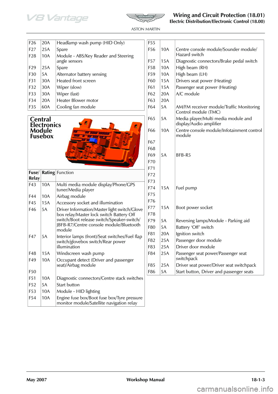
F26 20A Headlamp wash pump (HID Only)
F27 25A Spare
F28 10A Module - ABS/Key Reader and Steering angle sensors
F29 25A Spare
F30 5A Alternator battery sensing
F31 30A Heated front screen
F32 30A Wiper (slow)
F33 30A Wiper (fast)
F34 20A Heater Blower motor
F35 60A Cooling fan module
Central
Electronics
Module
Fusebox
Fuse/
RelayRatingFunction
F43 10A Multi media module display/Phone/GPS tuner/Media player
F44 10A Airbag module
F45 15A Accessory socket and illumination
F46 5A Driver Information/Master light switch/Glove box relay/Master lock switch Battery Off
switch/Boot release switch/Speaker-switch/
JBFB-R7/Centre console module/Bluetooth
module
F47 5A Interior lamps (front)/Seat switches/Fuel flap switch/glovebox switch/Rear power
illumination
F48 15A Windscreen wash pump
F49 10A Occupant detect (Driver and passenger seat)/Airbag module
F50
F51 10A Diagnostic connectors/Centre stack switches
F52 5A Start button
F53 10A Module - HID lighting
F54 10A Engine fuse box/Boot fuse box/Tyre pressure monitor module/Satellite navigation relay
F55
F56 10A Centre console module/Sounder module/
Hazard switch
F57 15A Diagnostic connectors/Brake pedal switch
F58 10A High beam (RH)
F59 10A High beam (LH)
F60 15A Drivers seat power (Heating)
F61 15A Passenger seat power (Heating)
F62 20A A/C module
F63 20A
F64 5A AM/FM receiver module/Traffic Monitoring Control module (TMC)
F65 5A Media player/Multi media module and display/Audio amplifier
F66 10A Centre console module/Infotainment control module
F67
F68
F69 5A BFB-R5
F70
F71
F72
F73
F74 15A Fuel pump
F75
F76
F77 15A Boot power socket
F78
F79 5A Reversing lamps/Module - Parking aid
F80 5A Battery ‘Off’ switch
F81 20A Ignition switch
F82 25A Passenger door module
F83 25A Driver door module
F84 25A Passenger seat power/Passenger seat switchpack
F85 25A Driver seat power/Driver seat switchpack
F86 5A Start button, Driver and passenger seats