instrument panel ASTON MARTIN V8 VANTAGE 2010 Owner's Manual
[x] Cancel search | Manufacturer: ASTON MARTIN, Model Year: 2010, Model line: V8 VANTAGE, Model: ASTON MARTIN V8 VANTAGE 2010Pages: 947, PDF Size: 43.21 MB
Page 106 of 947

Instrument Panel (IP) (01.12)
Body System (01.00)1-9-18 Workshop Manual Issue 5, January 2010
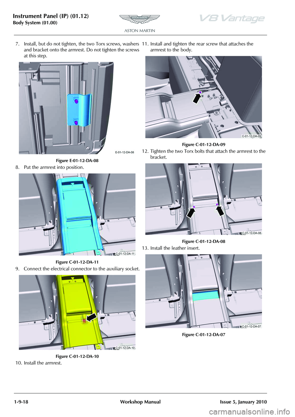
7. Install, but do not tighten, the two Torx screws, washers and bracket onto the armrest. Do not tighten the screws
at this step.
Figure E-01-12-DA-08
8. Put the armrest into position.
Figure C-01-12-DA-11
9. Connect the electrical connector to the auxiliary socket.
Figure C-01-12-DA-10
10. Install the armrest. 11. Install and tighten the rear screw that attaches the
armrest to the body.
Figure C-01-12-DA-09
12. Tighten the two Torx bolts that attach the armrest to the bracket.
Figure C-01-12-DA-08
13. Install the leather insert.
Figure C-01-12-DA-07
Page 107 of 947

Instrument Panel (IP) (01.12)
Body System (01.00)
Issue 5, January 2010 Workshop Manual 1-9-19
14. Install and tighten the two Torx bolts that attach the armrest to the body.
Figure C-01-12-DA-06
15. Install the rubber mat into the cup holder.
Figure C-01-12-DA-05
16. Install the rear finisher.
Figure C-01-12-DA-04
17. Install and tighten the five screws that attach the rear finisher to the body.
Figure C-01-12-DA-03
18. Install the rear infill panel.
Figure C-01-12-DA-02
19. Operate the front seats to their initial positions.
Centre Console Panel - Remove and
Install (Roadster Only)
Removal
1. Operate the front seats to their fully forward positions.
2. Disconnect the battery.
Repair Operation Time (ROT)
Page 108 of 947

Instrument Panel (IP) (01.12)
Body System (01.00)1-9-20 Workshop Manual Issue 5, January 2010
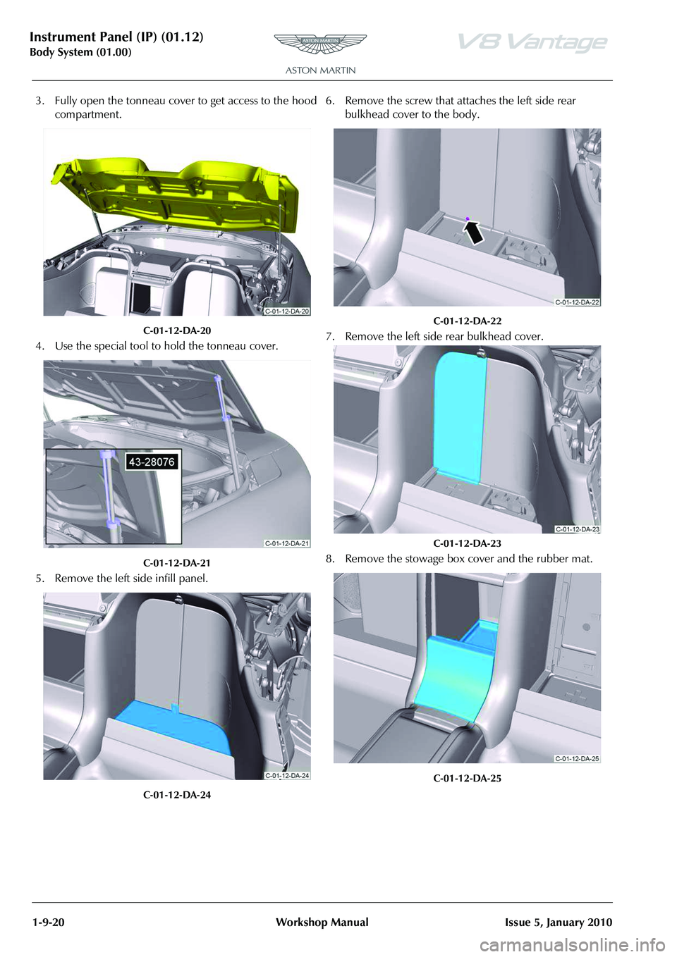
3. Fully open the tonneau cover to get access to the hood compartment.
C-01-12-DA-20
4. Use the special tool to hold the tonneau cover.
C-01-12-DA-21
5. Remove the left side infill panel.
C-01-12-DA-24
6. Remove the screw that attaches the left side rear bulkhead cover to the body.
C-01-12-DA-22
7. Remove the left side rear bulkhead cover.
C-01-12-DA-23
8. Remove the stowage box cover and the rubber mat.
C-01-12-DA-25
Page 109 of 947

Instrument Panel (IP) (01.12)
Body System (01.00)
Issue 5, January 2010 Workshop Manual 1-9-21
9. Remove the two screws that attach the left side cover panel for the centre console to the body.
C-01-12-DA-26
10. Remove the two nuts that attach the left side cover panel for the centre console to the body.
C-01-12-DA-27
11. Remove the left side cover panel for the centre console.
C-01-12-DA-28
12. Remove the right side infill panel.
C-01-12-DA-29
13. Remove the screw that attaches the right side rear bulkhead cover to the body.
C-01-12-DA-30
14. Remove the right side rear bulkhead cover.
C-01-12-DA-31
Page 110 of 947

Instrument Panel (IP) (01.12)
Body System (01.00)1-9-22 Workshop Manual Issue 5, January 2010
15. Remove the two screws that attach the right side cover panel for the centre console to the body.
C-01-12-DA-32
16. Remove the two nuts that attach the right side cover panel for the centre console to the body.
C-01-12-DA-33
17. Remove the right side cover panel for the centre console.
C-01-12-DA-34
18. Remove the four Torx screws and the four nuts that attach the stowage compartment cover to the body.
C-01-12-DA-35
19. Remove the stowage compartment cover.
C-01-12-DA-36
20. Remove the screw that attaches the stowage compartment to the body.
C-01-12-DA-37
Page 111 of 947

Instrument Panel (IP) (01.12)
Body System (01.00)
Issue 5, January 2010 Workshop Manual 1-9-23
21. Remove the four Torx screws that attach the stowage compartment to the body.
C-01-12-DA-38
22. Remove the two screws that attach the stowage compartment to the body.
C-01-12-DA-39
23. Remove the rubber mat from the cup holder.
C-01-12-DA-05
24. Remove the two Torx screws that attach the armrest to the bracket.
C-01-12-DA-06
25. Remove the leather insert.
C-01-12-DA-07
26. Remove the two Torx screws that attach the armrest to the body.
C-01-12-DA-08
Note: The bracket an d washers will fall from the armrest in
the step that follows.
Page 112 of 947

Instrument Panel (IP) (01.12)
Body System (01.00)1-9-24 Workshop Manual Issue 5, January 2010
27. Move the stowage box and remove the armrest.
C-01-12-DA-40
28. Remove the two screws that attach the centre console panel to the body.
C-01-12-DA-13
29. Push the gear knob down and turn it counterclockwise.
C-01-12-DA-14
30. Remove the gear knob. 31. Release the centre console panel from the body.
C-01-12-DA-17
32. Disconnect the electrical
connector from each of the
four switches.
C-01-12-DA-18
33. Remove the centre console panel.
Install
1. Connect the four electrical connector to each of the four switches (refer to Figure C-01-12-DA-18).
2. Put the centre console panel into position.
C-01-12-DA-19
3. Install the centre console panel.
4. Install the gearknob.
Page 113 of 947

Instrument Panel (IP) (01.12)
Body System (01.00)
Issue 5, January 2010 Workshop Manual 1-9-25
5. Push the gearknob down and turn it clockwise.
C-01-12-DA-15
6. Install and tighten the two screws that attach the centre console panel to the body.
C-01-12-DA-13
7. Install but do not tighten, the two Torx screws, washers and bracket to the armrest.
E-01-12-DA-08
8. Move the stowage box and install the armrest.
C-01-12-DA-40
9. Tighten the two Torx scrws th at attach the armrest to the
bracket.
C-01-12-DA-06
10. Install and tighten the two Torx screws that attach the armrest to the body.
C-01-12-DA-08
Page 114 of 947

Instrument Panel (IP) (01.12)
Body System (01.00)1-9-26 Workshop Manual Issue 5, January 2010
11. Install the leather insert.
C-01-12-DA-07
12. Install the rubber mat into the cupholder.
C-01-12-DA-05
13. Install and tighten the two screws that attach the stowage compartment to the body.
C-01-12-DA-39
14. Install and tighten the four Torx screws that attach the stowage compartment to the body.
C-01-12-DA-38
15. Install and tighten the screw that attaches the stowage compartment to the body.
C-01-12-DA-37
16. Install the stowage compartment cover.
C-01-12-DA-36
Page 115 of 947

Instrument Panel (IP) (01.12)
Body System (01.00)
Issue 5, January 2010 Workshop Manual 1-9-27
17. Install and tighten the four Torx screws and the four nuts that attach the stowage compartment cover to the body.
C-01-12-DA-35
18. Install the right side cover panel for the centre console.
C-01-12-DA-34
19. Install and tighten the two nuts that attach the right side cover panel for the centre console to the body.
C-01-12-DA-33
20. Install and tighten the two screws that attach the right side cover panel for the centre console to the body.
C-01-12-DA-32
21. Install the right side rear bulkhead cover.
C-01-12-DA-31
22. Install and tighten the screw that attaches the right side rear bulkhead cover to the body.
C-01-12-DA-30