wheel ASTON MARTIN V8 VANTAGE 2010 Owner's Manual
[x] Cancel search | Manufacturer: ASTON MARTIN, Model Year: 2010, Model line: V8 VANTAGE, Model: ASTON MARTIN V8 VANTAGE 2010Pages: 947, PDF Size: 43.21 MB
Page 210 of 947

Bumpers (01.19)
Body System (01.00)1-13-2 Workshop Manual May 2007
Specifications
Maintenance
Front Bumper Cover - Renew
Removal
1. Raise vehicle on ramp.
2. Remove front number plate and plinth (see Workshop Manual procedure 01.19.BD Licence Plate - Plinth
Assembly - Front - Renew).
3. Remove valance (see Workshop Manual procedure 01.19.AF Panel - Front Valance - Renew).
4. Remove screws (x2) securing front of undertray to bumper (see Figure 1).
5. Remove screws (x5) LH front wheel arch liner to bumper.
6. Remove screws (x5) RH front wheel arch liner to bumper.
7. Remove bolts (x3 securing LH air box to mounting brackets.
8. Remove bolts (x3 securing RH air box to mounting brackets. 9. Remove bolts (x6) securing bumper to front wing (see
Figure 2)
.
10. With assistance, release bumper from clips (x2) and
remove bumper (see Figure 3).
11. Remove mesh (clips x8).
Installation
1. Install mesh (clips x8).
2. With assistance position bumper and secure in clips (x2).
3. Install bolts (x6) bumper to front wing.
4. Install bolts (x3 securing RH air box to mounting brackets.
5. Install bolts (x3 securing LH air box to mounting brackets.
6. Install screws (x5) LH front wheel arch liner to bumper.
7. Install screws (x5) RH front wheel arch liner to bumper.
8. Install screws (x2) securing front undertray to bumper.
Torque Figures
DescriptionNm
Front Bumper to bumper bracket 4-5
Rear Bumper to Bumper Bracket 2-3
Repair Operation Time (ROT)
01-19-005
Figure 2
Figure 3
Remove Bolts x6
Front Bumper
01-19-001
01-19-004
Page 211 of 947
Bumpers (01.19)
Body System (01.00)
May 2007 Workshop Manual 1-13-3
9. Install number plate and plinth (see Workshop Manual procedure 01.19.BD Licence Plate - Plinth Assembly -
Front - Renew).
10. Install valance (see Workshop Manual procedure 01.19.AF Panel - Front Valance - Renew).
11. Lower vehicle on ramp.
Rear Bumper Cover - Renew
Removal
1. Raise vehicle on ramp.
2. Remove number plate.
3. Remove LH rear lamp assembly (see Workshop Manual procedure 17.03.AB Lamp Assembly (Rear) - LH
Renew).
4. Remove RH rear lamp assembly (see Workshop Manual procedure 17.03.BB XREF: 280 Lamp Assembly (Rear) -
RH Renew).
5. Remove wheel arch liner LH (see Workshop Manual procedure 01.02.JB Wheel Arch Liner - Rear - RH -
Renew).
6. Remove wheel arch liner RH (see Workshop Manual procedure 01.02.HB Wheel Arch Liner - Rear - LH -
Renew).
7. Remove tyre mobility kit from the rack.
8. Remove torx bolts located behind carpets to rear wings (x2).
9. Remove bolts (x2) in rear light recess.
10. Remove bolts securing bumper to wheel arch (6).
11. Remove bolts (x4) securing bumper to brackets.
12. With assistance Release bumper from body.
13. Release fir trees securing harness to bumper (x6).
14. Release remaining harness clips from bumper (x6).
15. Disconnect multiplugs to parking aid sensors (x2).
16. Disconnect multiplugs to license plate lamps (x2).
17. Remove nuts (x6) securing exhaust finishers to bumper.
18. Remove number plate light assembly (clips x5).
19. Remove parking aid sensors (x2)
20. Remove screw retaining clips (x13)
Installation
1. Install screw retaining clips x13.
2. Install parking aid sensors x2.
3. Install number pl ate light assembly
4. Install exhaust finishers to bumper.
5. With assistance position bumper to body.
6. Connect multiplugs to license plate lamps X2.
7. Connect multiplug to parking aid sensors.
8. Secure harness to bumper (f ir trees x6 and clips x6)
9. Install bumper bolts to brackets and body (x10). 10. Install tyre mobility kit to rack.
11. Install number plate.
12. Install RH rear lamp asse
mbly (see Workshop Manual
procedure 17.03.BB Lamp Assembly (Rear) - RH
Renew).
13. Install LH rear lamp assembly (see Workshop Manual procedure 17.03.AB Lamp Assembly (Rear) - LH
Renew).
14. Install wheel arch liner LH (see Workshop Manual procedure 01.02.JB Wheel Arch Liner - Rear - RH -
Renew).
15. Install RH wheel arch li ner (see Workshop Manual
procedure 01.02.HB Wheel Arch Liner - Rear - RH -
Renew).
16. Lower vehicle on ramp.
Repair Operation Time (ROT)
Page 215 of 947
Restraining Devices (01.20)
Body System (01.00)
May 2007 Workshop Manual 1-14-3
Airbag System
The airbag system is designed to provide increased collision
protection for front seat occu pants in addition to that
provided by the safety belt system. Safety belt use is
necessary to obtain the best occupant protection and to
receive the full advantages of the airbag system.
This vehicle is equipped with dr iver, passenger, side impact
airbags and seat belt pretensioners, which are electrically
controlled an RCM (Restraints Control Module).
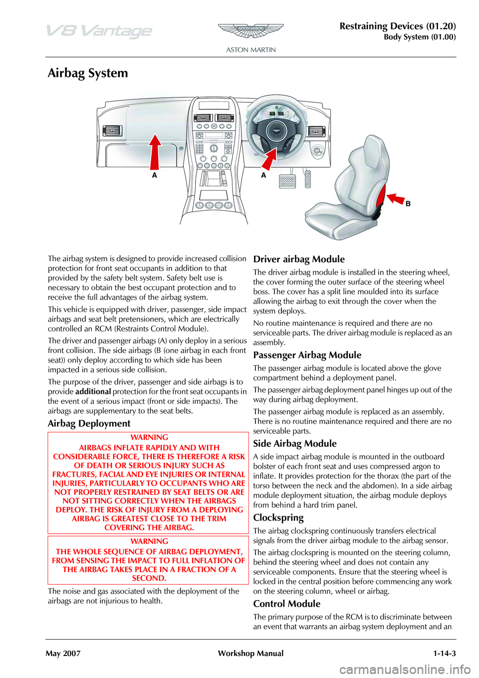
The driver and passenger airbags (A) only deploy in a serious
front collision. The side airbags (B (one airbag in each front
seat)) only deploy according to which side has been
impacted in a serious side collision.
The purpose of the driver, passenger and side airbags is to
provide additional protection for the front seat occupants in
the event of a serious impact (front or side impacts). The
airbags are supplementary to the seat belts.
Airbag Deployment
The noise and gas associated with the deployment of the
airbags are not injurious to health.
Driver airbag Module
The driver airbag module is installed in the steering wheel,
the cover forming the outer surface of the steering wheel
boss. The cover has a split line moulded into its surface
allowing the airbag to exit through the cover when the
system deploys.
No routine maintenance is required and there are no
serviceable parts. The driver airbag module is replaced as an
assembly.
Passenger Airbag Module
The passenger airbag module is located above the glove
compartment behind a deployment panel.
The passenger airbag deployment panel hinges up out of the
way during airbag deployment.
The passenger airbag module is replaced as an assembly.
There is no routine maintenance required and there are no
serviceable parts.
Side Airbag Module
A side impact airbag module is mounted in the outboard
bolster of each front seat and uses compressed argon to
inflate. It provides protection for the thorax (the part of the
torso between the neck and the abdomen). In a side airbag
module deployment situation, the airbag module deploys
from behind a hard trim panel.
Clockspring
The airbag clockspring continuously transfers electrical
signals from the driver airbag module to the airbag sensor.
The airbag clockspring is mounted on the steering column,
behind the steering wheel and does not contain any
serviceable components. Ensure that the steering wheel is
locked in the central position before commencing any work
on the steering column, wheel or airbag.
Control Module
The primary purpose of the RCM is to discriminate between
an event that warrants an airbag system deployment and an
R P
N
D
WAR NI N G
AIRBAGS INFLATE RAPIDLY AND WITH
CONSIDERABLE FORCE, THERE IS THEREFORE A RISK OF DEATH OR SERIOUS INJURY SUCH AS
FRACTURES, FACIAL AND EY E INJURIES OR INTERNAL
INJURIES, PARTICULARLY TO OCCUPANTS WHO ARE NOT PROPERLY RESTRAINED BY SEAT BELTS OR ARE NOT SITTING CORRECTLY WHEN THE AIRBAGS
DEPLOY. THE RISK OF IN JURY FROM A DEPLOYING
AIRBAG IS GREATEST CLOSE TO THE TRIM COVERING THE AIRBAG.
WAR NI N G
THE WHOLE SEQUENCE OF AIRBAG DEPLOYMENT,
FROM SENSING THE IMPACT TO FULL INFLATION OF THE AIRBAG TAKES PLACE IN A FRACTION OF A SECOND.
Page 216 of 947
Restraining Devices (01.20)
Body System (01.00)1-14-4 Workshop Manual May 2007
event that does not. The RCM governs the operation of the
whole system and performs continual system diagnostics.
Information on the severity of an impact is received from the
impact sensors.
Variations in the deployment of the front airbag modules are
dependent on the status of the front safety belt buckles.
Dual Inflation Technology
When activated, the airbags will deploy at either a normal or
reduced level of inflation, depending on crash severity.
Various sensors determine the direction and severity of an
impact. The system analyses this information then deploys
the appropriate airbags.
Impact Sensors
Side Impact - Side impact sensors are mounted to the base
of each B-pillar and within each door. In the event of a side
impact, the RCM processes the impact data sent by the side
impact sensor against stored data. The RCM will deploy the
side airbag on the side the deployment request was initiated
and the seat belt pretensioner.
Front Impact - Front impact sensors (x2) are located under
the grill opening panel.
The SRS module processes the impact data sent by the front
impact sensor against stored data, and deploys the front
airbags, and the seat belt pretensioners.
Passenger Airbag Deactivation
The passenger airbag can be deactivated using the PAD
(Passenger Airbag Deactivation) switch. Switching the
passenger airbag off allows children under the age of 12 to
be carried safely in the passenger seat. The PAD switch is
located at the passenger end of the instrument panel and is
accessible when the pa ssenger door is open.
Maintenance
Driver’s Airbag Module - Renew
Removal
1. Disconnect vehicle battery.
2. Allow a two minute power down period to de-activate
airbag system.
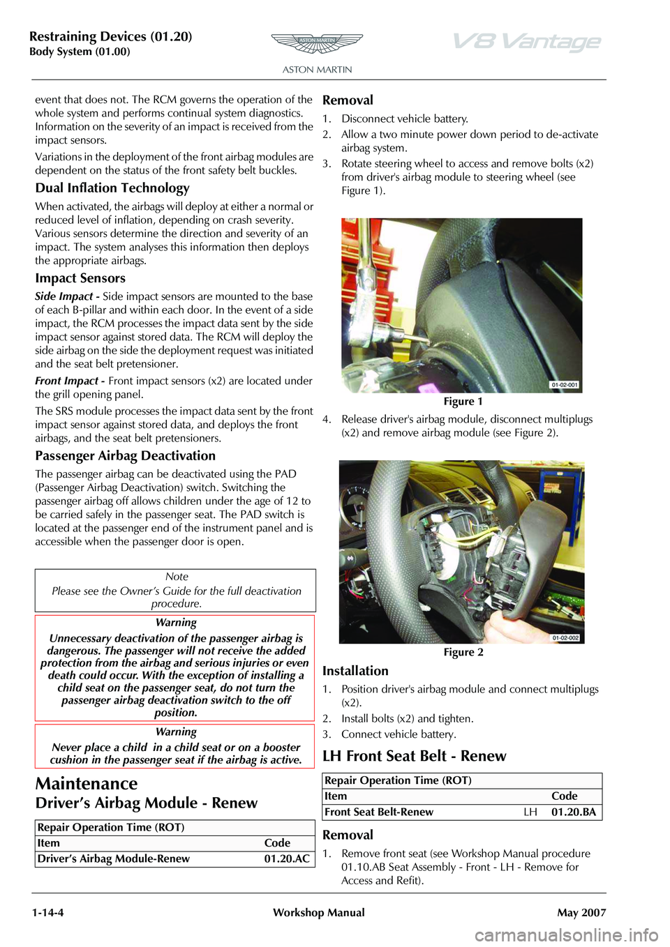
3. Rotate steering wheel to access and remove bolts (x2) from driver's airbag module to steering wheel (see
Figure 1).
4. Release driver's airbag mo dule, disconnect multiplugs
(x2) and remove airbag module (see Figure 2).
Installation
1. Position driver's airbag mo dule and connect multiplugs
(x2).
2. Install bolts (x2) and tighten.
3. Connect vehicle battery.
LH Front Seat Belt - Renew
Removal
1. Remove front seat (see Workshop Manual procedure 01.10.AB Seat Assembly - Front - LH - Remove for
Access and Refit).
Note
Please see the Owner’s Guid e for the full deactivation
procedure.
Warning
Unnecessary deactivation of the passenger airbag is
dangerous. The passenger will not receive the added
protection from the airbag and serious injuries or even
death could occur. With the exception of installing a child seat on the passenge r seat, do not turn the
passenger airbag deactiva tion switch to the off
position.
Warning
Never place a child in a child seat or on a booster
cushion in the passenger seat if the airbag is active.
Repair Operation Time (ROT)
Figure 1
Figure 2
Repair Operation Time (ROT)
ItemCode
Front Seat Belt-Renew LH01.20.BA
Page 224 of 947
Subframes (02.03)
Frame and Mounting (02.00)
2-1-2 Workshop Manual May 2007
Frame and Mounting (02.00)
Subframes (02.03)
Specifications
Maintenance
Front Subframe-Renew
Removal
1. Switch battery isolation switch ‘OFF’.
2. Raise vehicle on ramp.
3. Remove RH wheel arch liner (see Workshop Manual procedure 01.02.GB Wheel Arch Liner - Front - RH -
Renew).
4. Remove LH wheel arch liner (see Workshop Manual procedure 01.02.FB Wheel Arch Liner - Front - LH -
Renew)
5. Remove road wheel/s.
6. Remove front spring/damper assemblies (see Workshop Manual procedure 04.03.AA Spring and Damper
Assembly - Front Pair - Renew).
7. Remove nuts (x2) from track rod ends to vertical link.
8. Using special tool 204-523, release track rod end from vertical link.
9. Disconnect ABS sensor multiplugs then release sensor harness clips (x6) from upper suspension arm and
vertical link.
10. Disconnect brake pad wear sensor multiplug then release sensor harness clips (x2) from upper suspension
arms. 11. Remove Allen bolts (x4) from brake callipers to vertical
link and tie callipers aside.
12. Remove Torx screws (x4) from brake disc to hub and remove brake disc.
13. Remove anti-roll bar links nuts (x2) and washers (x2).
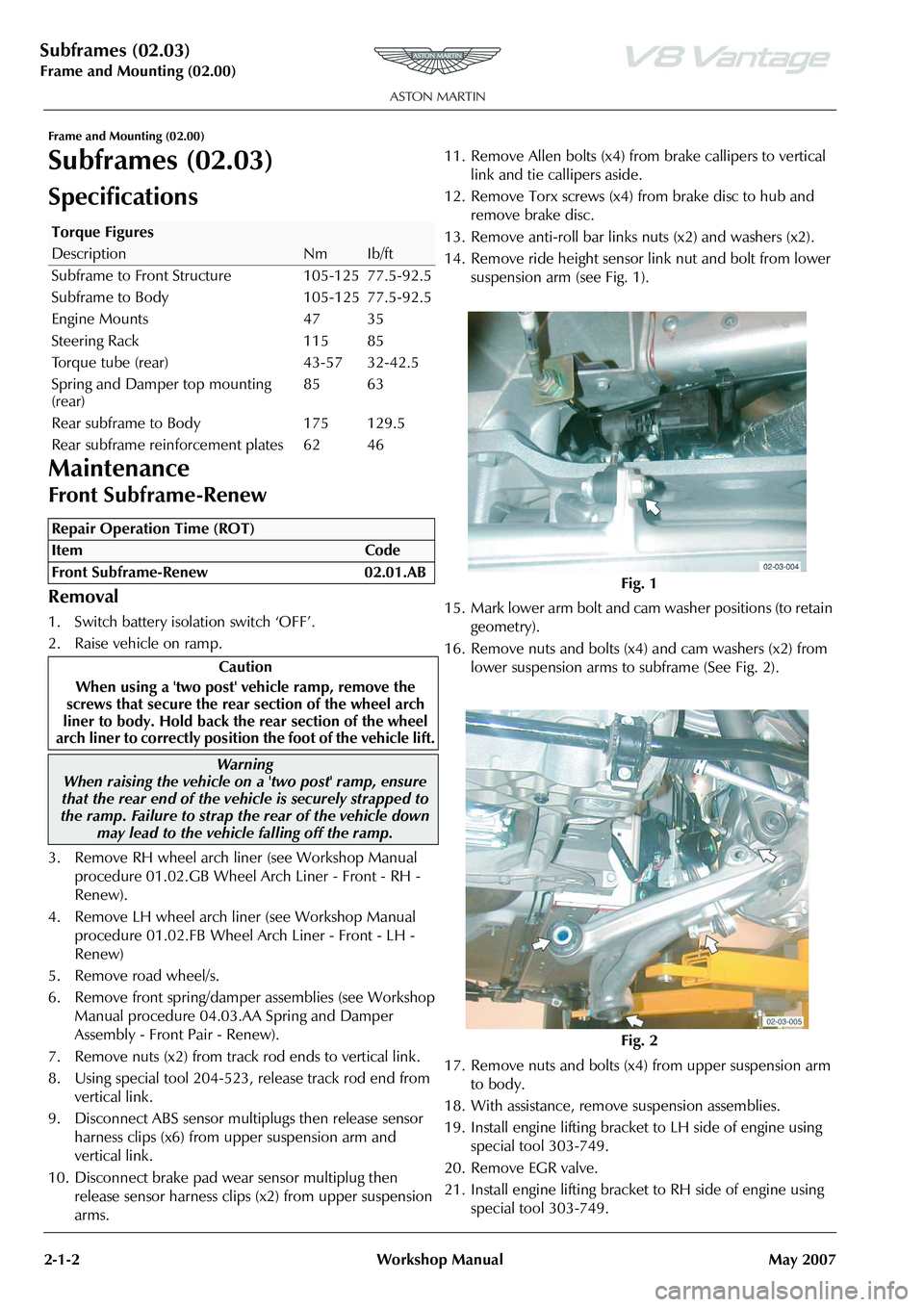
14. Remove ride height sensor link nut and bolt from lower
suspension arm (see Fig. 1).
15. Mark lower arm bolt and cam washer positions (to retain
geometry).
16. Remove nuts and bolts (x4) and cam washers (x2) from lower suspension arms to subframe (See Fig. 2).
17. Remove nuts and bolts (x4) from upper suspension arm to body.
18. With assistance, remove suspension assemblies.
19. Install engine lifting bracket to LH side of engine using special tool 303-749.
20. Remove EGR valve.
21. Install engine lifting bracket to RH side of engine using special tool 303-749.
Torque Figures
DescriptionNmIb/ft
Subframe to Front Structure 105-125 77.5-92.5
Subframe to Body 105-125 77.5-92.5
Engine Mounts 47 35
Steering Rack 115 85
Torque tube (rear) 43-57 32-42.5
Spring and Damper top mounting
(rear) 85 63
Rear subframe to Body 175 129.5
Rear subframe reinforcement plates 62 46
Repair Operation Time (ROT)
Warning
When raising the vehicle on a 'two post' ramp, ensure
that the rear end of the vehi cle is securely strapped to
the ramp. Failure to strap th e rear of the vehicle down
may lead to the vehicl e falling off the ramp.
Fig. 1
Fig. 2
Page 225 of 947
Subframes (02.03)
Frame and Mounting (02.00)
May 2007 Workshop Manual 2-1-3
22. Install cross brace support brackets 303-021-02 (x6).
23. Support engine using special tool SPX M553D.
24. Remove undertray (see Workshop Manual procedure 01.02.NB Undertray - Front - Renew).
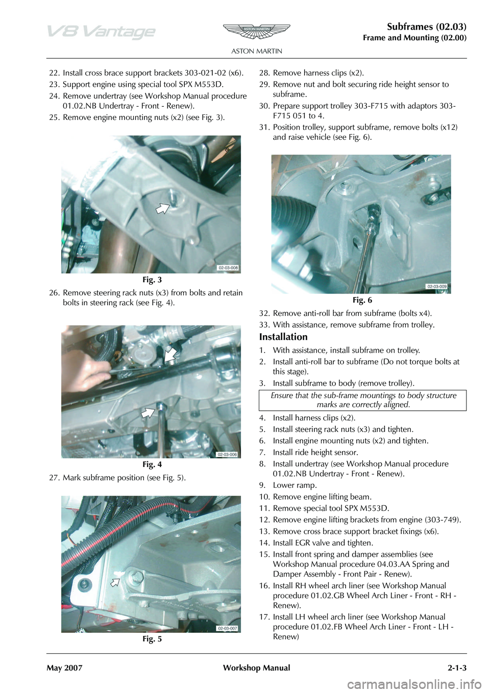
25. Remove engine mounting nuts (x2) (see Fig. 3).
26. Remove steering rack nuts (x3) from bolts and retain bolts in steering rack (see Fig. 4).
27. Mark subframe position (see Fig. 5). 28. Remove harness clips (x2).
29. Remove nut and bolt securi
ng ride height sensor to
subframe.
30. Prepare support trolley 30 3-F715 with adaptors 303-
F715 051 to 4.
31. Position trolley, support subframe, remove bolts (x12)
and raise vehicle (see Fig. 6).
32. Remove anti-roll bar from subframe (bolts x4).
33. With assistance, remove subframe from trolley.
Installation
1. With assistance, install subframe on trolley.
2. Install anti-roll bar to subframe (Do not torque bolts at this stage).
3. Install subframe to body (remove trolley).
4. Install harness clips (x2).
5. Install steering rack nuts (x3) and tighten.
6. Install engine mounting nuts (x2) and tighten.
7. Install ride height sensor.
8. Install undertray (see Workshop Manual procedure 01.02.NB Undertray - Front - Renew).
9. Lower ramp.
10. Remove engine lifting beam.
11. Remove special tool SPX M553D.
12. Remove engine lifting brack ets from engine (303-749).
13. Remove cross brace suppo rt bracket fixings (x6).
14. Install EGR valve and tighten.
15. Install front spring and damper assemblies (see Workshop Manual procedure 04.03.AA Spring and
Damper Assembly - Front Pair - Renew).
16. Install RH wheel arch li ner (see Workshop Manual
procedure 01.02.GB Wheel Arch Liner - Front - RH -
Renew).
17. Install LH wheel arch liner (see Workshop Manual procedure 01.02.FB Wheel Arch Liner - Front - LH -
Renew)
Fig. 3
Fig. 4
Fig. 5
Fig. 6
Ensure that the sub-frame mo untings to body structure
marks are correctly aligned.
Page 226 of 947
Subframes (02.03)
Frame and Mounting (02.00)
2-1-4 Workshop Manual May 2007
18. With assistance, install suspension assemblies, lower suspension arms, nuts and bolts and cam washers
(x2)(do not torque tighten at this stage).
19. Install upper suspension arms to body (do not torque tighten at this stage).
20. Install ride height sensor link to lower suspension arm and tighten.
21. Install and tighten nuts (x2) from track rod ends to vertical link.
22. Install anti-roll bar to links nuts and washers (x2) and tighten.
23. Clean and install brake discs and install and tighten Torx screws (x4)).
24. Install brake callipers and to rque tighten Allen bolts (x4).
25. Connect brake pad wear sensor multiplug and secure harness clips (x4) in upper suspension arms.
26. Connect ABS sensor multiplugs and secure harness clips (x6) in upper suspension arms and vertical links.
27. Install road wheel/s.
28. Lower vehicle on ramp.
29. Torque tighten suspension nuts and bolts.
30. Battery isolation switch ‘ON’.
31. 4 wheel alignment check and adjust (See Workshop Manual procedure 04.00.AD 4 Wheel Alignment -
Check and Adjust).
Front Subframe-Remove/Refit
Removal
1. Switch battery isolation switch ‘OFF’.
2. Raise vehicle on ramp.
3. Remove road wheel(s).
4. Remove RH wheel arch liner (See Workshop Manual procedure 01.02.GB Wheel Arch Liner - Front - RH -
Renew).
5. Remove LH wheel arch liner (See Workshop Manual procedure 01.02.FB Wheel Arch Liner - Front - LH -
Renew). 6. Remove front spring and damper assemblies (See
Workshop Manual proced ure 04.03.AA Spring &
Damper Assembly - Front Pair - Renew).
7. Remove nuts (x2) from track rod ends to vertical link.
8. Using special tool 204 - 52, release track rod end from vertical link.
9. Disconnect ABS sensor mu ltiplug and release sensor
harness clips (x6) from upper suspension arm and
vertical link.
10. Disconnect brake pad wear sensor multiplug and release sensor harness clips (x4) from upper suspension arm.
11. Remove Allen bolts (x4) from brake callipers to vertical link and tie callipers aside.
12. Remove Torx screws (x4) from brake disc to hub and remove brake disc.
13. Remove anti-roll bar links nuts (x2) and washers (x2).
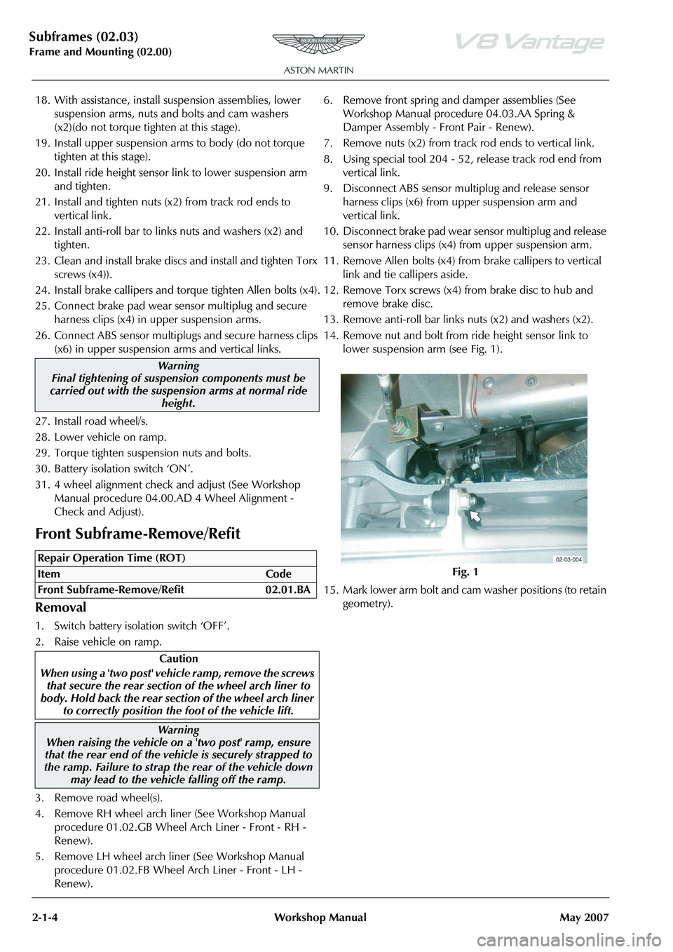
14. Remove nut and bolt from ride height sensor link to lower suspension arm (see Fig. 1).
15. Mark lower arm bolt and cam washer positions (to retain
geometry).
Warning
Final tightening of suspension components must be
carried out with the suspension arms at normal ride
height.
Repair Operation Time (ROT)
Warning
When raising the vehicle on a 'two post' ramp, ensure
that the rear end of the vehi cle is securely strapped to
the ramp. Failure to strap th e rear of the vehicle down
may lead to the vehicl e falling off the ramp.
Fig. 1
Page 228 of 947
Subframes (02.03)
Frame and Mounting (02.00)
2-1-6 Workshop Manual May 2007
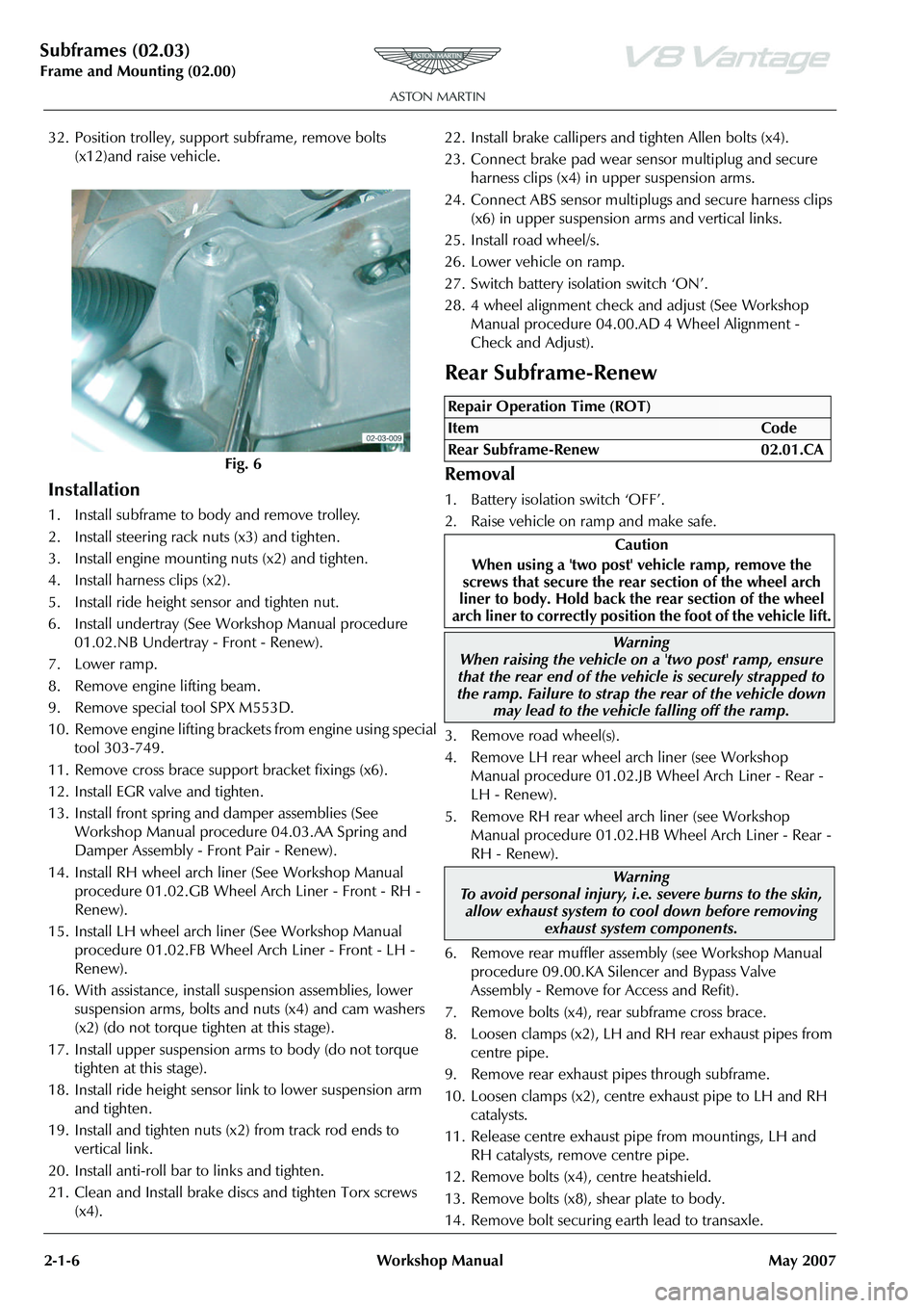
32. Position trolley, support subframe, remove bolts (x12)and raise vehicle.
Installation
1. Install subframe to body and remove trolley.
2. Install steering rack nuts (x3) and tighten.
3. Install engine mounting nuts (x2) and tighten.
4. Install harness clips (x2).
5. Install ride height sensor and tighten nut.
6. Install undertray (See Workshop Manual procedure 01.02.NB Undertray - Front - Renew).
7. Lower ramp.
8. Remove engine lifting beam.
9. Remove special tool SPX M553D.
10. Remove engine lifting bracket s from engine using special
tool 303-749.
11. Remove cross brace support bracket fixings (x6).
12. Install EGR valve and tighten.
13. Install front spring and damper assemblies (See Workshop Manual procedure 04.03.AA Spring and
Damper Assembly - Front Pair - Renew).
14. Install RH wheel arch liner (See Workshop Manual procedure 01.02.GB Wheel Arch Liner - Front - RH -
Renew).
15. Install LH wheel arch liner (See Workshop Manual procedure 01.02.FB Wheel Arch Liner - Front - LH -
Renew).
16. With assistance, install suspension assemblies, lower suspension arms, bolts and nuts (x4) and cam washers
(x2) (do not torque tighten at this stage).
17. Install upper suspension arms to body (do not torque tighten at this stage).
18. Install ride height sensor link to lower suspension arm and tighten.
19. Install and tighten nuts (x2) from track rod ends to vertical link.
20. Install anti-roll bar to links and tighten.
21. Clean and Install brake discs and tighten Torx screws (x4). 22. Install brake callipers and tighten Allen bolts (x4).
23. Connect brake pad wear se
nsor multiplug and secure
harness clips (x4) in upper suspension arms.
24. Connect ABS sensor multiplu gs and secure harness clips
(x6) in upper suspension arms and vertical links.
25. Install road wheel/s.
26. Lower vehicle on ramp.
27. Switch battery isolation switch ‘ON’.
28. 4 wheel alignment check and adjust (See Workshop Manual procedure 04.00.AD 4 Wheel Alignment -
Check and Adjust).
Rear Subframe-Renew
Removal
1. Battery isolation switch ‘OFF’.
2. Raise vehicle on ramp and make safe.
3. Remove road wheel(s).
4. Remove LH rear wheel arch liner (see Workshop Manual procedure 01.02.JB Wheel Arch Liner - Rear -
LH - Renew).
5. Remove RH rear wheel arch liner (see Workshop Manual procedure 01.02.HB Wheel Arch Liner - Rear -
RH - Renew).
6. Remove rear muffler asse mbly (see Workshop Manual
procedure 09.00.KA Silencer and Bypass Valve
Assembly - Remove for Access and Refit).
7. Remove bolts (x4), rear subframe cross brace.
8. Loosen clamps (x2), LH and RH rear exhaust pipes from
centre pipe.
9. Remove rear exhaust pipes through subframe.
10. Loosen clamps (x2), centre exhaust pipe to LH and RH
catalysts.
11. Release centre exhaust pipe from mountings, LH and RH catalysts, remove centre pipe.
12. Remove bolts (x4), centre heatshield.
13. Remove bolts (x8), shear plate to body.
14. Remove bolt securing earth lead to transaxle.
Fig. 6
Repair Operation Time (ROT)
ItemCode
Rear Subframe-Renew 02.01.CA
Caution
When using a 'two post' vehicle ramp, remove the
screws that secure the rear section of the wheel arch
liner to body. Hold back the rear section of the wheel
arch liner to correctly position the foot of the vehicle lift.
Warning
When raising the vehicle on a 'two post' ramp, ensure
that the rear end of the vehi cle is securely strapped to
the ramp. Failure to strap th e rear of the vehicle down
may lead to the vehicl e falling off the ramp.
Warning
To avoid personal injury, i.e. severe burns to the skin, allow exhaust system to cool down before removing
exhaust system components.
Page 229 of 947
Subframes (02.03)
Frame and Mounting (02.00)
May 2007 Workshop Manual 2-1-7
15. Use tool (206-103) and release each handbrake cable from mounting brackets, re lease inner cable eyelets
from calliper levers.
16. Remove bolts (x2) and nuts (x2), handbrake cables to subframe.
17. Use tool (206-103) and release handbrake cables from subframe brackets.
18. Release handbrake cable from clip, tie handbrake cable aside.
19. Loosen and disconnect each brake pipe from body bracket. Plug brake pipes
.
20. Remove bolt, fuel filler pipe to damper mounting.
21. Remove nut securing fuel fi ller pipe to body, tie filler
pipe aside.
22. Remove bolts (x4 each side), securing spring/damper assemblies.
23. Position drain tray to collect oil spillage.
24. Loosen and disconnect unions (x2), transaxle oil cooler.
Plug pipe connections.
25. Remove drain tray.
26. Disconnect multiplug, release harness clips (x2), transaxle harness, RH rear wheel arch.
27. Mark subframe position to body.
28. Position subframe trolley (303-F715), under subframe.
29. Lower vehicle until subfra me rests on support trolley.
30. Remove bolts (x6), securing subframe to body.
31. Raise vehicle to gain access to gear selector cables.
32. Using (308-642), release se lector cables (x2) from ball
joints, release selector cables from bracket.
33. Remove torque tube to transaxle bolts (x8).
34. Move subframe support trolley rearwards to give a clearance between torque tube and transaxle.
35. Carefully raise vehicle from subframe.
Installation
1. Clean transaxle and mating face on torque tube.
2. Position subframe assembly underneath vehicle.
3. Lower vehicle to align transaxle to propshaft splines.
4. Move subframe assembly forward, engage propshaft splines, locating dowels, transaxle to torque tube.
5. Install bolts (x8), torque tube to transaxle, torque tighten bolts.
6. Install gear selector cables on levers and in bracket.
7. Lower vehicle onto subframe mountings, align to marks, install and torque tighten bolts (x6).
8. Position spring/damper assemblies, install bolts (x8).
9. Position fuel filler pipe, install and torque tighten bolt.
10. Position fuel filler pipe to body, install and tighten nut to correct torque.
11. Position handbrake cables to subframe, install bolts (x4), torque bolts. 12. Install handbrake cables to callipers.
13. Remove plugs, install brake pipes.
14. Remove plugs, install transaxle oil cooler pipes, tighten
unions to correct torque.
15. Position earth lead to transaxle, install and torque tighten bolt.
16. Install transaxle harness multiplug, secure harness clips (x2).
17. Install shear plate, install and torque tighten bolts (x8).
18. Install heat shield, install and torque tighten bolts (x4).
19. Clean exhaust pipe connections, apply exhaust sealant to connections.
20. Install centre pipe to mountings and catalysts, torque tighten clamp nuts.
21. Install rear exhaust pipes to centre pipe, torque tighten clamp nuts.
22. Position subframe cross brace, install and torque bolts.
23. Install rear muffler (see Workshop Manual procedure 09.00.KA Silencer and Bypass Valve Assembly - Remove
for Access and Refit).
24. Install LH rear wheel arch liner (see Workshop Manual procedure 01.02.JB Wheel Arch Liner - Rear - LH -
Renew).
25. Install RH rear wheel arch liner (see Workshop Manual procedure 01.02.HB Wheel Arch Liner - Rear - RH -
Renew).
26. Bleed brake system (see Workshop Manual procedure 06.07.DD Brake Hydraulic System - Flush/Refill/Bleed
27. Adjust handbrake (see Wo rkshop Manual procedure
06.05.DC Handbrake Cable Assembly - Adjust).
28. Install road Wheel(s).
29. Lower vehicle on ramp and remove safety equipment.
Rear Subframe-Remove/Refit
Removal
1. Disconnect vehicle battery.
2. Remove rear subframe asse mbly (see Workshop Manual
procedure 02.01.CA Subframe Assembly - Rear -
Remove for Access and Refit).
3. Mark driveshafts to transaxle flanges for assembly purposes.
4. Remove and discard Allen bolts (x12), collect plates (x6), driveshaft flanges to transaxle.
5. Attach slings to transaxle, connect suitable hoist and
take weight of transaxle.
6. Remove nuts (x2). hydramounts to subframe.
7. With assistance, raise and remove transaxle from subframe.
Caution
Always plug pipe connections to prevent ingress of dirt.
Repair Operation Time (ROT)
Page 230 of 947
Subframes (02.03)
Frame and Mounting (02.00)
2-1-8 Workshop Manual May 2007
8. Remove bolts (x2), remove both spring/damper assemblies.
9. Remove nuts (x2), anti-roll bar links to lower suspension
arms.
10. Remove bolts (x4). anti-roll bar to subframe. Remove anti-roll bar.
11. Disconnect ABS sensor mult iplugs (x2), release sensor
harness clips (x4) from both toe control arms.
12. Disconnect brake pad wear sensor multiplugs (x2). Release connectors (x2) from subframe.
13. Loosen and disconnect brake pipe unions (x2) from subframe brackets. Pl ug pipe connections.
14. Disconnect multiplug fr om ride height sensor.
15. Remove nut/bolt securing ride height sensor link to
upper suspension arm.
16. Remove bolts (x2), ride height sensor to subframe. Remove sensor.
17. Remove nuts/bolts (x2) and cam washers (x2), toe control arms to subframe.
18. Remove bolts (x2), nuts/bolts (x2) and cam washers (x2),
securing lower suspension arms to subframe
19. Remove nuts/bolts (x4), upper suspension arms to subframe.
20. With assistance, remove suspension assemblies from subframe.
21. Remove heatshield clips (x2) from rear of subframe.
22. Release clips (x23), ha rness to subframe, remove
harness.
23. Release brake pipes from cl ips (x7), remove pipes (x2).
24. Remove brake pipe clips (x5) from subframe.
Installation
1. Clean suspension components and brake pipes.
2. Instal brake pipe clips (x5) in subframe.
3. Install brake pipes (x2) in clips (x7).
4. Install harness and secure with clips (x23).
5. Install heatshield clips (x2).
6. With assistance, install suspension assemblies in subframe.
7. Install bolts/nuts (x4), upper suspension arm to subframe. Do not torque tighten at this stage.
8. Install bolts (x2), bolts/nuts (x2) and cam washers (x2) securing lower suspension arm to subframe. Do not
torque tighten at this stage.
9. Position toe control arm, install bolts (x2, cam washers (x2 and nuts (x2). Do not torque tighten at this stage.
10. Install ride height sensor, in stall and torque tighten bolts
(x2).
11. Align ride height sensor li nk to upper suspension arm,
install bolt/nut, tighten to correct torque.
12. Connect multiplug to ride height sensor. 13. Remove pipe plugs, install and torque tighten brake
pipe unions.
14. Connect brake pad wear sensor multiplugs, install in subframe brackets.
15. Connect ABS sensor multiplugs (x2), install harness clips (x4), in toe control arms.
16. Install anti-roll bar, install bolts (x4). Do not torque tighten at this stage.
17. Align anti-roll bar links to lower suspension arms. Install nuts (x2), do not torque tighten at this stage.
18. Install spring/damper assemblies (x2). Install bolts (x2), do not torque tighten at this stage
19. With assistance, install transaxle in subframe. Install and torque tighten hydramount nuts (x2).
20. Lower hoist, remove slings.
21. Align driveshafts to transaxle flanges, install plates (x6), new Allen bolts (x12) and tighten to correct torque.
22. Install rear subframe asse mbly (see Workshop Manual
procedure 02.01.CA Subframe Assembly - Rear -
Remove for Access and Refit).
23. Connect vehicle battery.
24. 4 wheel alignment check/adjust (see Workshop Manual procedure 04.00.AD 4 Wheel Alignment - Check and
Adjust).
25. Final torque tighten all suspension nuts/bolts.
RH/LH Transmission Rear Hydromount
Isolator Assembly-Renew
Removal
1. Raise vehicle on ramp.
2. Remove rear exhaust silenc er (see Workshop Manual
procedure 09.00.KA Silencer and Bypass Valve
Assembly - Remove for Access and Refit).
3. Remove bolts (x4) from subframe cross brace.
4. Loosen clamp nut and release rear exhaust pipe from centre pipe.
5. Remove rear exhaust pipe through subframe.
6. Position hydraulic lift er to support transaxle.
Caution
Always plug pipe connections to prevent ingress of dirt.
New Allen bolts should have a thread lock coating.
Caution
Final tightening of suspension components must be
carried out with the suspensi on arms at normal ride
height.
Repair Operation Time (ROT)
ItemCode
Transmission Rear Hydromount
Isolator Assembly-Renew RH
02.03.BC
Transmission Rear Hydromount
Isolator Assembly-Renew LH
02.03.BD
Warning
To avoid personal injury, i.e. severe burns to the skin, allow exhaust system to cool down before removing
exhaust system components.