wheel ASTON MARTIN V8 VANTAGE 2010 Repair Manual
[x] Cancel search | Manufacturer: ASTON MARTIN, Model Year: 2010, Model line: V8 VANTAGE, Model: ASTON MARTIN V8 VANTAGE 2010Pages: 947, PDF Size: 43.21 MB
Page 407 of 947
Power Conversion (03.11)
Engine (03.00)
May 2007 Workshop Manual 3-11-35
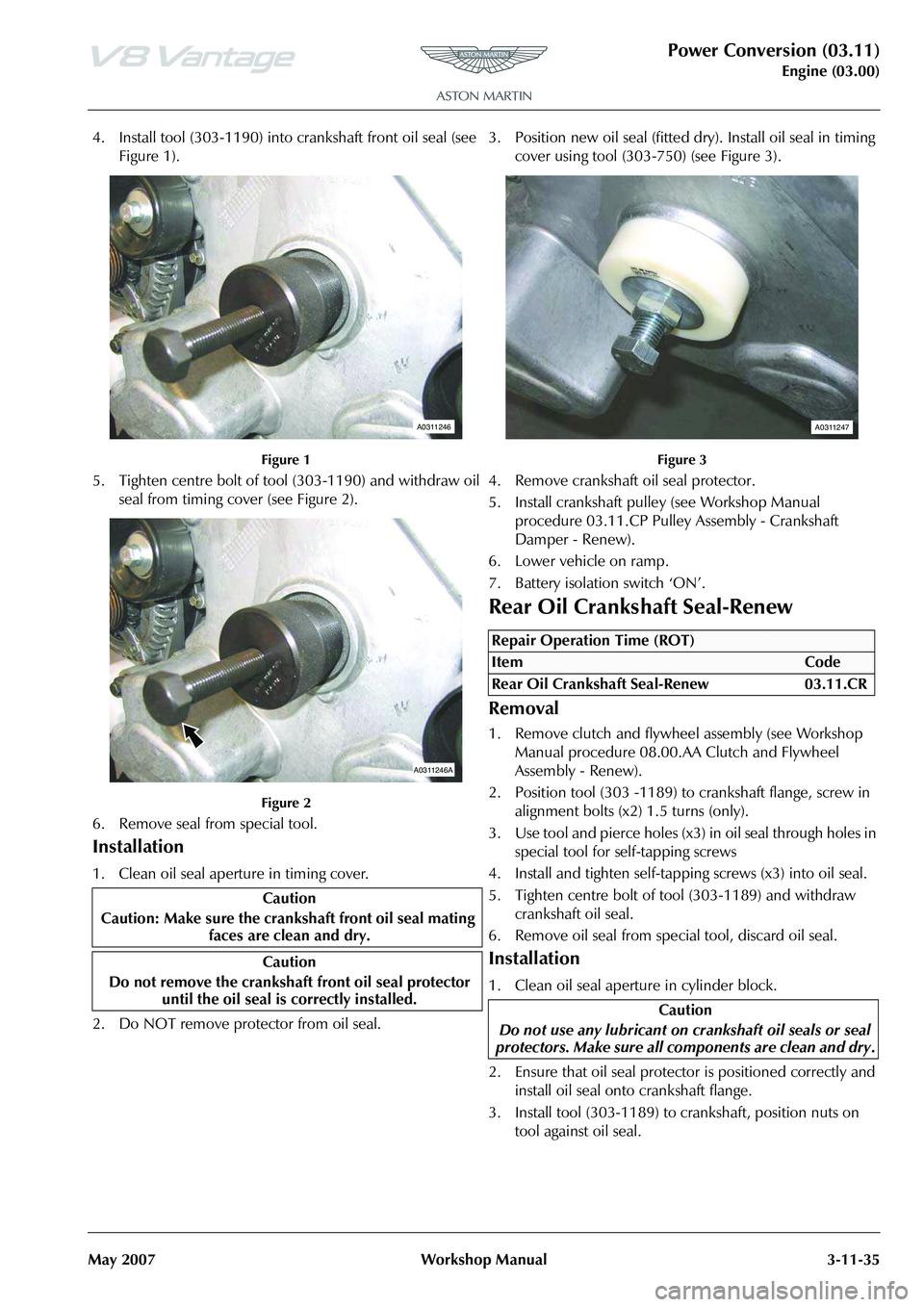
4. Install tool (303-1190) into crankshaft front oil seal (see
Figure 1).
Figure 1
5. Tighten centre bolt of tool (303-1190) and withdraw oil seal from timing cover (see Figure 2).
Figure 2
6. Remove seal from special tool.
Installation
1. Clean oil seal aperture in timing cover.
2. Do NOT remove protector from oil seal. 3. Position new oil seal (fitted dry). Install oil seal in timing
cover using tool (303-750) (see Figure 3).
Figure 3
4. Remove crankshaft oil seal protector.
5. Install crankshaft pulley (see Workshop Manual procedure 03.11.CP Pulley Assembly - Crankshaft
Damper - Renew).
6. Lower vehicle on ramp.
7. Battery isolation switch ‘ON’.
Rear Oil Crankshaft Seal-Renew
Removal
1. Remove clutch and flywheel assembly (see Workshop Manual procedure 08.00.AA Clutch and Flywheel
Assembly - Renew).
2. Position tool (303 -1189) to crankshaft flange, screw in alignment bolts (x2) 1.5 turns (only).
3. Use tool and pierce holes (x3) in oil seal through holes in special tool for self-tapping screws
4. Install and tighten self-tapping screws (x3) into oil seal.
5. Tighten centre bolt of tool (303-1189) and withdraw crankshaft oil seal.
6. Remove oil seal from spec ial tool, discard oil seal.
Installation
1. Clean oil seal aperture in cylinder block.
2. Ensure that oil seal protecto r is positioned correctly and
install oil seal onto crankshaft flange.
3. Install tool (303-1189) to crankshaft, position nuts on
tool against oil seal.
Caution
Caution: Make sure the cranks haft front oil seal mating
faces are clean and dry.
Caution
Do not remove the crankshaft front oil seal protector
until the oil seal is correctly installed.
A0311246
A0311246A
Repair Operation Time (ROT)
A0311247
Page 408 of 947
Power Conversion (03.11)
Engine (03.00)3-11-36 Workshop Manual May 2007
4. Ensure that oil seal and special are parallel to rear of
engine.
5. To install oil seal, tighten nuts alternately on tool (303- 1189) until oil seal correctly seated.
6. Remove special tool from crankshaft.
7. Check that the oil seal is located correctly.
8. Install clutch and flywheel assembly (see Workshop Manual procedure 08.00.AA Clutch and Flywheel
Assembly - Renew).
Cylinder Block-Renew
Removal
1. Remove cylinder head gasket - engine set (see Workshop Manual procedure 03.01.HW Gasket -
Cylinder Head - Engine Set - Renew With Engine
Removed).
2. Remove crankshaft assembly.
3. Remove pistons and connecting rod assemblies from cylinder block.
4. Remove Torx screws (x4) securing engine oil cooling
valves to cylinder block.
5. Remove engine oil cooling valves (x4).
6. Remove bolts (x5) securing water pump to cylinder block. Remove water pump, discard gasket.
7. Remove cylinder block valley cover.
Installation
1. Clean cylinder block valley cover and mating face on cylinder block.
2. Install cylinder block valley cover.
3. Clean engine oil cooling valves.
4. Install engine oil cooling valves in cylinder block.
5. Install and torque tighten Torx screws (x4).
6. Clean connecting rods and piston assemblies.
7. Correctly position ring gaps on pistons prior to installation.
8. Remove connecting rod bearing caps.
9. Install bearings in connecting rods and bearing caps.
10. Lubricate cylinder bores, pistons and rings with clean engine oil.
11. Install special tools (303-535) to the connecting rod to prevent damage to crankshaft journal.
12. Install crankshaft assembly.
13. Install new gasket, water pump, install and torque tighten bolts (x5). 14. Install cylinder head gasket - engine set (see Workshop
Manual procedure 03.01.HW Gasket - Cylinder Head -
Engine Set - Renew Wi th Engine Removed).
Crankshaft Damper Pulley Assembly-
Renew (with Engine Removed)
Removal
1. Remove engine assembly (see Workshop Manual
procedure 03.00.AA Engine Assembly - Renew).
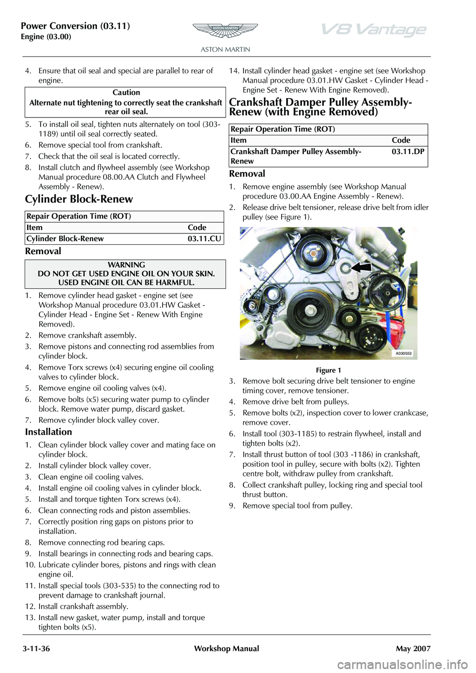
2. Release drive belt tensioner, release drive belt from idler pulley (see Figure 1).
Figure 1
3. Remove bolt securing drive belt tensioner to engine timing cover, remove tensioner.
4. Remove drive belt from pulleys.
5. Remove bolts (x2), inspection cover to lower crankcase, remove cover.
6. Install tool (303-1185) to restrain flywheel, install and tighten bolts (x2).
7. Install thrust button of tool (303 -1186) in crankshaft,
position tool in pulley, secure with bolts (x2). Tighten
centre bolt, withdraw pulley from crankshaft.
8. Collect crankshaft pulley, locking ring and special tool thrust button.
9. Remove special tool from pulley.
Caution
Alternate nut tightening to correctly seat the crankshaft rear oil seal.
Repair Operation Time (ROT)
WAR NI NG
DO NOT GET USED ENGINE OIL ON YOUR SKIN.
USED ENGINE OIL CAN BE HARMFUL.
Repair Operation Time (ROT)
ItemCode
Crankshaft Damper Pulley Assembly-
Renew 03.11.DP
A030553
Page 410 of 947

Power Conversion (03.11)
Engine (03.00)3-11-38 Workshop Manual May 2007
3. Position new oil seal (fitted dry). Install oil seal in timing
cover using tool (303-750) (see Figure 3).
Figure 3
4. Remove crankshaft oil seal protector.
5. Install crankshaft pulle y (see Workshop Manual
procedure 03.11.DP Pulley Assembly - Crankshaft
Damper - Renew With Engine Removed).
Crankshaft Rear Oil Seal-Renew (with
Engine Removed
)
Removal
1. Remove engine assembly (see Workshop Manual
procedure 03.00.AA Engi ne Assembly - Renew).
2. Remove bolts (x2), inspection cover to lower crankcase, remove cover.
3. Install tool (303-1185) to restrain flywheel, install and tighten bolts (x2).
4. Remove bolts (x6), clutch cover to flywheel.
5. Release clutch cover from dowels (x3), remove clutch cover, collect drive plate.
6. Remove and discard bolts (x8), flywheel to crankshaft flange.
7. Remove bolts (x2), collect tool (303-1185).
8. Release flywheel from dowel, remove flywheel.
9. Position tool (303-1189) to crankshaft flange, screw in
alignment bolts (x2) 1.5 turns (only).
10. Use tool and pierce holes (x3) in oil seal through holes in special tool for self-tapping screws
11. Install and tighten self-tapping screws (x3) into oil seal.
12. Tighten centre bolt of tool (303-1189) and withdraw crankshaft oil seal.
13. Remove oil seal from special tool, discard oil seal.
Installation
1. Clean oil seal aperture in cylinder block.
2. Ensure that oil seal protector is positioned correctly and install oil seal onto crankshaft flange.
3. Install tool (303-1189) to crankshaft, position nuts on
tool against oil seal.
4. Ensure that oil seal and special are parallel to rear of engine.
5. To install oil seal, tighten nuts alternately on tool (303- 1189) until oil seal correctly seated.
6. Remove special tool from crankshaft.
7. Check that the oil seal is located correctly.
8. Clean flywheel and mating face on crankshaft.
9. Install flywheel, align to dowel on crankshaft flange.
10. Install new bolts (x8), install tool (303-1185) to restrain flywheel. Torque tighten bolts (x8) in the correct
sequence.
11. Clean clutch cover and drive plate.
12. Install clutch assembly on flywheel, align to dowels (x3).
13. Install bolts (x6), install clutch alignment tool, evenly torque tighten bolts (x6) in a diagonal sequence.
Remove clutch alignment tool.
14. Remove bolts (x2), collect tool (303-1185).
15. Install inspection cover, install and torque tighten bolts (x2).
16. Install engine assembly (see Workshop Manual procedure 03.00.AA Engine Assembly - Renew).
Repair Operation Time (ROT)
A0311247
Caution
Do not use any lubricant on cr ankshaft oil seals or seal
protectors. Make sure all co mponents are clean and dry
Caution
Alternate nut tightening to correctly seat the crankshaft rear oil seal.
Page 411 of 947
Air Charging (03.12)
Engine (03.00)
Issue 4, November 2008 Workshop Manual 3-12-1
Engine (03.00)
Air Charging (03.12)
Maintenance
Remove
1. Raise the vehicle and make it safe.
2. Remove the front road wheel at the side of the air filter
to be removed.
3. Apply protective tape to the wheelarch area of the front wing to prevent damage.
4. Remove the front outside screw that attaches the valance.
Repair Operation Time (ROT)
Repair Operation Time (ROT)
Page 412 of 947

Air Charging (03.12)
Engine (03.00)3-12-2 Workshop ManualIssue 4, November 2008
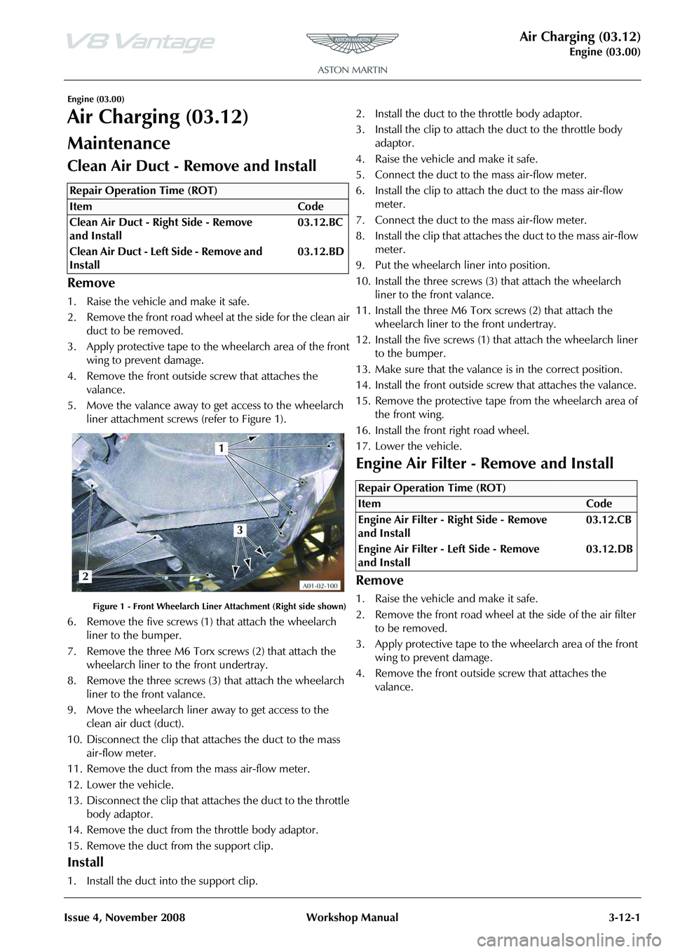
5. Move the valance away to get access to the wheelarch
liner attachment screws (refer to Figure 1).
Figure 1 - Front Wheelarch Liner Attachment (Right side shown)
6. Remove the five screws (1) that attach the wheelarch liner to the bumper.
7. Remove the three M6 Torx screws (2) that attach the wheelarch liner to the front undertray.
8. Remove the three screws (3) that attach the wheelarch liner to the front valance.
9. Move the wheelarch liner away to get access to the air filter box.
10. Remove the seven self-tapping screws that attach the base of the air cleaner.
11. Remove the the base of the air cleaner.
12. Remove the air filter element.
Installation
1. Clean the air cleaner box and base.
2. Install the air filter element.
3. Remove the the base of the air cleaner.
4. Install the seven self-tapping screws that attach the base of the air cleaner.
5. Put the wheelarch liner back into position.
6. Install the three screws (3) that attach the wheelarch liner to the front valance (refer to Figure 1).
7. Install the three M6 Torx screws (2) that attach the wheelarch liner to the front undertray.
8. Install the five screws (1) that attach the wheelarch liner to the bumper.
9. Make sure that the valance is in the correct position.
10. Install the front outside screw that attaches the valance.
11. Remove the protective tape from the wheelarch.
12. Install the front road wheel.
13. Lower the vehicle.
Engine Air Cleaner Assembly - Remove
and Install
Remove
1. Raise the vehicle and make it safe.
2. Remove the front road wheel at the side for the air filter box to be removed.
3. Apply protective tape to the wheelarch area of the front wing to prevent damage.
4. Remove the front outside screw that attaches the valance.
5. Move the valance away to get access to the wheelarch liner attachment screws (refer to Figure 1).
Figure 1 - Front Wheelarch Liner Attachment (Right side shown)
6. Remove the five screws (1) that attach the wheelarch liner to the bumper.
7. Remove the three M6 Torx screws (2) that attach the wheelarch liner to the front undertray.
8. Remove the three screws (3) that attach the wheelarch liner to the front valance.
9. Move the wheelarch liner away to get access to the air filter box.
10. Remove the self-tapping screw that attaches the mass air-flow meter to the air filter box.
11. Disconnect the mass air-flow meter from the air filter box.
12. Disconnect the air inlet duct from the air filter box .
13. Remove the three M6 screws that attach the air filter box.
14. Remove the air filter box.
Install
1. Put the air filter box in position.
2. Install the three M6 screws that attach the air box.
3. Connect the air inlet duct to the air filter box.
4. Connect the mass air-flow meter to the air filter box
Repair Operation Time (ROT)
ItemCode
Engine Air Cleaner Assembly - Right
Side - Remove and Install 03.12.DJ
Engine Air Cleaner Assembly - Left Side
- Remove and Install 03.12.DH
Page 413 of 947

Air Charging (03.12)
Engine (03.00)
Issue 4, November 2008 Workshop Manual 3-12-3
5. Install the self-tapping screw that attaches the mass air-
flow meter to the air filter box.
6. Put the wheelarch liner back into position.
7. Install the three screws (3) that attach the wheelarch liner to the front valance (refer to Figure 1).
8. Install the three M6 Torx screws (2) that attach the wheelarch liner to the front undertray.
9. Install the five screws (1) th at attach the wheelarch liner
to the bumper.
10. Make sure that the valance is in the correct position.
11. Install the front outside screw that attaches the valance.
12. Remove the protective tape from the wheelarch.
13. Install the front road wheel.
14. Lower the vehicle.
Page 419 of 947
Engine Management System (03.14)
Engine (03.00)
Issue 5, Janauary 2010 Workshop Manual 3-14-3
Removal
1. Raise vehicle on ramp.
2. Remove rear exhaust silencer (refer to Workshop Manual procedure 09.00.KA Silencer and Bypass Valve
Assembly - Remove for Access and Refit).
3. Disconnect multiplugs (x2), HEGO sensors.
4. Secure sufficient lengths of string to HEGO sensor multiplugs for assembly purposes.
5. Loosen LH and RH clamp nuts, catalysts to centre pipes.
6. With assistance, manoeuvre exhaust centre pipe assembly rearwards to release from catalysts.
7. Remove nuts (x3), catalyst to exhaust manifold.
8. Release and support weight of LH catalyst from exhaust manifold.
9. Manoeuvre HEGO sensor leads and remove cable tie. Release HEGO sensor leads from behind heat shield.
Remove string from HEGO multiplugs.
10. Remove catalyst assembly.
11. Remove and discard gasket.
12. Remove HEGO sensors from catalyst.
Installation
1. Clean catalyst, mating joint faces and HEGO sensors.
2. Install and tighten HEGO sensor to catalyst.
3. Apply proprietary exhaust se alant around clamp joints.
4. Install new gasket to exhaust manifold.
5. Position catalyst, secure string (x2) to HEGO multiplugs, feed sensor leads behind heat shield. Install catalyst to
exhaust manifold.
6. Instal land tighten nuts (x3), catalyst to exhaust manifold.
7. Align centre pipe assembly to catalyst, tighten clamp
nuts to.
8. Remove string (x2), conne ct multiplugs (x2), HEGO
sensors.
9. Install rear exhaust silencer (refer to Workshop Manual procedure 09.00.KA Silencer and Bypass Valve
Assembly - Remove for Access and Refit).
10. Lower vehicle on ramp.
Left Side Powertrain Control Module
(PCM) (Coupe Only) - Remove and
Install
Remove
1. Disconnect the ba ttery ground cable.
2. Remove the wheel and tyre. (refer to Workshop Manual procedure 04.04.EC - Wheel and Tyre)
3. Remove the six rear screws that attach the wheel-arch liner to the body.
4. Remove the rear screw that attaches the wheel-arch liner to the body.
5. Turn the steering fully to the right.
6. Move the wheel arch liner to get access to the Powertrain Control Module (PCM).
7. Disconnect the electrical connector from the direction
indicator.
8. Release the four fi r-tree clips that attach the wiring
harness for the direction indi cator and the screen wash
system.
9. Release the two fir tree clips that attach the wiring harness for the PCM.
10. Remove the three bolts that attach the PCM bottom bracket and PCM to the PCM top bracket.
11. Disconnect the three electrical connectors from the PCM.
12. Remove the PCM.
Install
1. Put the PCM in position.
2. Connect the three electrical connectors to the PCM.
3. Align the PCM to the top bracket.
4. Align the bottom bracket to the PCM.
5. Install and tighten the three bolts that attach the PCM bottom bracket and PCM to the PCM top bracket.
6. Install the two fir tree clips that attach the wiring harness for the PCM.
7. Attach the four fir-tree cl ips that attach the wiring
harness for the direction indi cator and the screen wash
system.
8. Connect the electrical connector to the direction indicator.
9. Put the wheel-arch liner into the correct position.
10. Install and tighten the rear screw that attaches the wheel-arch liner to the body.
11. Install and tighten the six rear screws that attach the wheel-arch liner to the body.
12. Move the steering to the centre position.
13. Connect the battery ground cable.
14. Install the wheel and tyre. (04.04.EC - Wheel and Tyre)
15. Connect AMDS.
16. Use AMDS to do a test of the PCM. (00.06.AD - AMDS Operation Check)
WA R N I N G
THE EXHAUST SYSTEM WILL BE VERY HOT AFTER OPERATION. LET THE EXHAUST SYSTEM COOL
BEFORE YOU DO WORK. IF YOU DO NOT, SEVERE
INJURY CAN OCCUR
Repair Operation Time (ROT)
Page 420 of 947

Engine Management System (03.14)
Engine (03.00)3-14-4 Workshop Manual Issue 5, Janauary 2010
Left Side Powertrain Control Module
(PCM) (Roadster Only) - Remove and
Install
Remove
1. Disconnect the battery ground cable.
2. Lift the vehicle on a four-post lift.
3. Remove the centre undertray. (refer to Workshop Manual procedure 01.02.MB - Centre Undertray)
4. Lower the vehicle.
5. Lift the vehicle on a two-post lift.
6. Remove the wheel and tyre. (refer to Workshop Manual procedure 04.04.EC - Wheel and Tyre)
7. Remove the six rear screws that attach the wheel-arch liner to the body.
8. Remove the rear screw that attaches the wheel-arch liner to the body.
9. Turn the steering fully to the right.
10. Move the wheel-arch liner to get access to the Powertrain Control Module (PCM).
11. Disconnect the electrical connector from the direction indicator.
12. Release the four fir tree cl ips that attach the wiring
harness for the direction indicator and the screen wash
system.
13. Release the two fir tree clips that attach the wiring harness for the PCM.
14. Remove the three screws that attach the PCM bottom bracket and PCM to the PCM top bracket.
15. Disconnect the three elec trical connectors from the
PCM.
16. Remove the PCM.
Install
1. Put the PCM in position.
2. Connect the three electrical connectors to the PCM.
3. Align the PCM with the top bracket.
4. Align the bottom bracket with the PCM.
5. Install and tighten the three screws that attach the PCM bottom bracket and PCM to the PCM top bracket.
6. Install the two fir tree clips that attach the wiring harness for the PCM.
7. Attach the four fir tree clips that attach the wiring harness for the indicator and the screen wash system.
8. Connect the electrical connector to the indicator.
9. Put the wheel-arch liner into the correct position.
10. Install and tighten the rear screw that attaches the wheel-arch liner to the body. 11. Install and tighten the six rear screws that attach the
wheel-arch liner to the body.
12. Install the centre undertray. (refer to Workshop Manual procedure 01.02.MB - Centre Undertray)
13. Install the wheel and tyre. (refer to Workshop Manual procedure 04.04.EC - Wheel and Tyre)
14. Move the steering to the centre position.
15. Connect the battery ground cable.
Repair Operation Time (ROT)
Page 425 of 947
Issue 6, May 2010 Workshop Manual 1-1-1
Suspension (04.00)
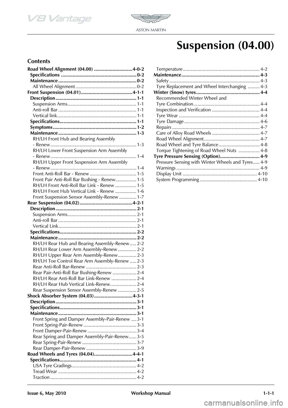
Contents
Road Wheel Alignment (04.00) ............................. 4-0-2Specifications ......................................................... 0-2
Maintenance ........................................................... 0-2All Wheel Alignment .............................................. 0-2
Front Suspension (04.01)....................................... 4-1-1 Description ............................................................. 1-1Suspension Arms .................................................... 1-1
Anti-roll Bar ........................................................... 1-1
Vertical link............................................................ 1-1
Specifications.......................................................... 1-1
Symptoms ............................................................... 1-2
Maintenance ........................................................... 1-3 RH/LH Front Hub and Bearing Assembly
- Renew ................................................................. 1-3
RH/LH Lower Front Suspension Arm Assembly
- Renew ................................................................. 1-4
RH/LH Upper Front Suspension Arm Assembly
- Renew ................................................................. 1-4
Front Anti-Roll Bar - Renew ................................... 1-5
Front Pair Anti-Roll Bar Bushing - Renew................ 1-5
RH/LH Front Anti-Roll Bar Link - Renew ................ 1-5
RH/LH Front Hub Vertical Link - Renew ................ 1-6
Front Suspension Sensor Assembly-Renew ............. 1-7
Rear Suspension (04.02) ........................................ 4-2-1 Description ............................................................. 2-1Suspension Arms .................................................... 2-1
Anti-roll Bar ........................................................... 2-1
Vertical Link........................................................... 2-1
Specifications.......................................................... 2-2
Maintenance ........................................................... 2-2 RH/LH Rear Hub and Bearin g Assembly-Renew ..... 2-2
RH/LH Rear Lower Arm Assembly-Renew .............. 2-2
RH/LH Upper Rear Arm Assembly-Renew .............. 2-3
RH/LH Toe Control Rear Arm Assembly-Renew ..... 2-3
Rear Anti-Roll Bar-Renew ...................................... 2-3
Rear Pair-Anti-Roll Bar Bushing-Renew .................. 2-4
RH/LH Rear Anti-Roll Bar Link-Renew ................... 2-4
RH/LH Rear Hub Vertical Link-Renew.................... 2-4
Rear Suspension Sensor Assembly-Renew .............. 2-5
Shock Absorber System (04.03) ............................. 4-3-1 Description ............................................................. 3-1
Specifications.......................................................... 3-1
Maintenance ........................................................... 3-1Front Spring and Damper Assembly-Pair-Renew .... 3-1
Front Spring-Pair-Renew ........................................ 3-3
Front Damper-Pair-Renew ..................................... 3-4
Rear Spring and Damper Assembly-Pair-Renew...... 3-5
Rear Spring-Pair-Renew ......................................... 3-7
Rear Damper-Pair-Renew ...................................... 3-9
Road Wheels and Tyres (04.04)............................. 4-4-1 Specifications.......................................................... 4-1USA Tyre Gradings................................................. 4-2
Tread Wear ........................................................... 4-2
Traction ................................................................. 4-2 Temperature .......................................................... 4-2
Maintenance ........................................................... 4-3 Safety .................................................................... 4-3
Tyre Replacement and Wheel Interchanging ......... 4-3
Winter (Snow) tyres ................................................ 4-4 Recommended Winter Wheel and
Tyre Combination .................................................. 4-4
Inspection and Verification . ................................... 4-4
Tyre Wear ............................................................. 4-4
Tyre Damage ......................................................... 4-6
Repairs .................................................................. 4-7
Care of Alloy Road Wheels .................................... 4-7
Road Wheel Alignment .......................................... 4-7
Road Wheel and Tyre Balance ............................... 4-8
Torque Tightening of Road Wheel Nuts ................ 4-8
Tyre Pressure Sensing (Option).............................. 4-9 Pressure Sensing with Wint er Wheels and Tyres ..... 4-9
Warnings ............................................................... 4-9
Display Unit ........................................................ 4-10
System Programming ........................................... 4-10
Page 426 of 947
Road Wheel Alignment (04.00)
Suspension (04.00)1-1-2 Workshop Manual Issue 6, May 2010
Suspension (04.00)
Road Wheel Alignment (04.00)
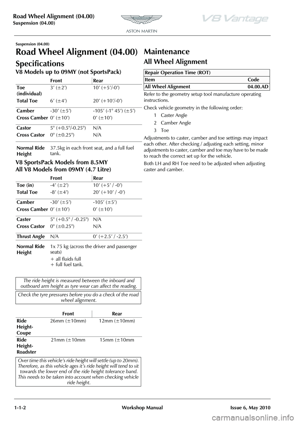
Specifications
V8 Models up to 09MY (not SportsPack)
V8 SportsPack Models from 8.5MY
All V8 Models from 09MY (4.7 Litre)
Maintenance
All Wheel Alignment
Refer to the geometry setup tool manufacture operating
instructions.
Check vehicle geometry in the following order:
1 Caster Angle
2 Camber Angle
3Toe
Adjustments to caster, camber and toe settings may impact
each other. After checking / adjusting each setting, minor
adjustments to caster, camber and toe may have to be made
to reach the correct set up for the vehicle.
Both LH and RH Toe need to be adjusted when adjusting
caster and camber.
Front Rear
Toe
(individual) 3’ (±2’) 10’ (+5’/-0’)
Total Toe 6’ (±4’) 20’ (+10’/-0’)
Camber -30’ (±5’) -105’ (-1° 45’) (±5’)
Cross Camber 0’ (±10’) 0’ (±10’)
Castor 5° (+0.5°/-0.25°) N/A
Cross Castor 0° (±0.25°) N/A
Normal Ride
Height 37.5kg in each front seat, and a full fuel
tank.
Front Rear
Toe (in) -4