Air bag ASTON MARTIN V8 VANTAGE 2010 Owner's Guide
[x] Cancel search | Manufacturer: ASTON MARTIN, Model Year: 2010, Model line: V8 VANTAGE, Model: ASTON MARTIN V8 VANTAGE 2010Pages: 947, PDF Size: 43.21 MB
Page 724 of 947
Wiring and Circuit Protection (18.01)
Electric Distribution/Electronic Control (18.00)
May 2007 Workshop Manual 18-1-35
11. Connect door harness to main harness multiplug and
secure boot.
12. Connect Crash sensor an d parking brake multiplugs.
13. Connect Fuel pump module, parking aid module (x2) and pre-tensioner multiplugs (clip to body).
14. Install earth header.
15. Install clips (x13).
16. Connect petrol tank multiplug and secure to body
17. Install harness clips (x2).
18. Pull harness from passenger compartment and secure grommet.
19. Connect crash sensor, battery disconnect switch and pre-tensioner multiplugs (clip to body x2).
20. Install battery header.
21. Install earth headers (x2).
22. Secure in-line fuse to body.
23. Secure harness to floor (bolts x4).
24. Install clips (x8).
25. Feed harness into tailgate area and secure grommet (LH).
26. Connect LH tailgate harness multiplug (clip to body).
27. Install LH harness clips (x3).
28. Connect RH tailgate ha rness multiplug (clipped to
body).
29. Feed harness into tailgate area and secure grommet (RH).
30. Install RH harness clips (x4).
31. Install nuts (x7) harness to tunnel.
32. Install earth headers (x2).
33. Connect Airbag module (x2) multiplugs.
34. Install harness clips (x3).
35. Install nuts (x3) harness to tunnel.
36. Install earth headers (x2).
37. Connect Yaw sensor multiplug.
38. Install earth headers (x2).
39. Install nuts (x3) harness to front bulkhead.
40. Install harness clips (x4).
41. Connect fuel filler flap release and interior light
multiplugs.
42. Push rear light harness through body and secure grommet.
43. Install new harness clips (x7).
44. Pull harness from interior, connect Lucar connectors (x2) to AM/FM tuner and clip service loop.
45. Connect GPS (x2) and AM/FM tuner multiplugs.
46. Install bolts (x4) and earth strap for Satellite Navigation mounting plate access.
47. Connect rear bumper harness (x2) and Subframe harness multiplugs (clipped to body x1).
48. Push harness into w/arch area and secure grommet.
49. Install wires to earth headers (x3).
50. Push rear light harness through body and fit grommet. 51. Secure harness to body (x3).
52. Connect Interior light, a
ccessory sockets (x2), battery
disconnect switch, power plug (clipped to body x4).
53. Install new harness clips (x4).
54. Feed harness from cabin th rough bulkhead into under
bonnet area and secure grommet.
55. Connect multiplugs forward harness to main harness (x3) (clip to body).
56. Connect (bolted) multiplug forward harness to main harness (clip to body).
57. Install brake booster (see Workshop Manual procedure 06.07.AB Brake Booster - RHD - Renew
58. Install footrest (bolts x4).
59. Install handbrake lever (bolts x4).
60. Install front floor carpet and a post trim panel.
61. Install multimedia module (see Workshop Manual procedure 19.07.BB Module - Multi Media - Renew).
62. Position LH and RH rear lamp assemblies and connect
multiplugs (x2).
63. Install rubber seals (x3), plain washers (x3), and star washers (x3). Install and tighten nuts (x3).
64. Position fusebox, connect main battery feed, install and torque tighten nut, install terminal cover.
65. Connect multiplugs (x2) and install fusebox in mounting bracket.
66. Install mobility kit.
67. Install tyre sealant bottle.
68. Install power amplifier (see Workshop Manual procedure 15.01.AB Power Amplifier - Renew).
69. Fit rear floor carpet - check procedure
70. Connect multiplug (x1) subwoofer.
71. Install subwoofer (nut x1 and bolt x1).
72. Install seat belt bracket (bolts x4).
73. Install speaker to LH and RH trim moulding (nuts x6).
74. Connect multiplug (x2) LH and RH speaker
75. Feed seatbelt/s through quarter trim moulding.
76. Install quarter trim moulding (bolts x2 and screw x1).
77. Install RH and LH quarter trim middle panel, secure
with clips, Install and tighten screw.
78. Install RH rear wheel arch liner (see Workshop Manual procedure 01.02.JB Wheel Arch Liner - Rear - RH -
Renew).
79. Install central electronic module (see Workshop Manual procedure 18.01.LC Module - Central Electronic -
Renew).
80. Install instrument panel (see Workshop Manual procedure 01.12.AB Instrument Panel - Facia Assembly
- Remove for Access and Refit).
81. Install front header panel (see Workshop Manual procedure 01.05.BB Panel Assembly - Header - Renew).
82. Connect vehicle battery.
Page 744 of 947
Special Tools - Pictorial Index
Appendix & Glossary
May 2007 Workshop Manual 20-1-5
205-793 (Rear Subframe Bush Installer)
310-040 (Fuel Pipe Disconnect Tool)
310-134 (Filler Neck Disconnect Tool)
310-140A (Fuel Pump Install/Remove)303-667 (Clutch Alignment)
501-108 (IP Alignment Pins)
501-073A (Airbag Simulators)
501-103 (Side Airbag and Pretensioner simulators)
Page 787 of 947

Squeaks and Rattles Repair Manual
July 2010 Page 3 of 21
Contents
Contents .................................................................................................................................3
Evaluation Drives - Squeak & Rattle Feedback Guidelines ....................................................4
Squeak and Rattle Terminology .............................................................................................5
Squeaks ........................................................................................................................................................... 5
Rattles ........................................................................................................................ ..................................... 5
NVH............................................................................................................................ .................................... 6
Steering Wheel Airbag Rattle ................................................................................................... ......................... 7
Repair: ........................................................................................................................ ................................. 7
Sat-Nav Lid Rattles ............................................................................................................ .....9
Sat-Nav Tappi ng Noise .......................................................................................................... .......................... 9
Repair ......................................................................................................................... ................................. 9
Sat-Nav Chatter ................................................................................................................ ............................. 13
Repair: ........................................................................................................................ ............................... 13
Sat-Nav Rattle (Loose in the aperture) ......................................................................................... ................... 17
Repair ......................................................................................................................... ............................... 17
Door Noises .................................................................................................................... .....21
Door Trim Panel Assembly Rattle ................................................................................................ ................... 21
Repair: ........................................................................................................................ ............................... 21
Page 791 of 947
Squeaks and Rattles Repair Manual
July 2010 Page 7 of 21
Steering Wheel Airbag Rattle
SRO: 01.20.CJ
Safe VINs: DBS - E01082, V8 Vantage - D13104, DB9 - A12179
Repair:
1. Put the Emotion Control Unit (ECU) into the docking station at position 2 to release the Electronic Steering
Column Lock (ESCL)
2. Disconnect the battery (refer to Workshop Manual procedure 14.01.CA).
WARNING:
WAIT FOR TWO MINUTES BEFORE YO U CONTINUE WITH THIS PROCEDURE. THIS IS TO MAKE SURE
THAT THERE IS NO POWER TO TH E AIRBAG SYSTEM. IF YOU DO NOT DO THIS, THE AIRBAG CAN
OPERATE SUDDENLY AND CAUSE INJURY
WARNING:
BE CAREFUL WHEN YOU HOLD AND MOVE THE AIRB AG UNIT. THE AIRBAG UNIT HAS AN EXPLOSIVE
CHARGE IN IT. IF YOU DO NOT HOLD THE UNIT CAREFULLY, THE CHARGE CAN OPERATE AND CAUSE
INJURY.
3. Turn the steering wheel to get access to the screws that attach the driver's airbag to the steering wheel.
Figure 1
4. Remove the screw that attaches the driver's airbag to the steering wheel.
Page 792 of 947
Squeaks and Rattles Repair Manual
Page 8 of 21 Issue 3
Figure 2
5. Install a bush (Part Number 9G43-33698-AA) onto th e airbag attachment screw (refer to Figures 3).
Figure 3
6. Install the screw and torque it to 9 Nm.
7. Turn the steering wheel to get access to the second airbag attachment screw.
8. Do steps 4 thru 6 again for the second airbag attachment screw.
9. Connect the battery (refer to Work shop Manual procedure 14.01.CA).
Page 903 of 947
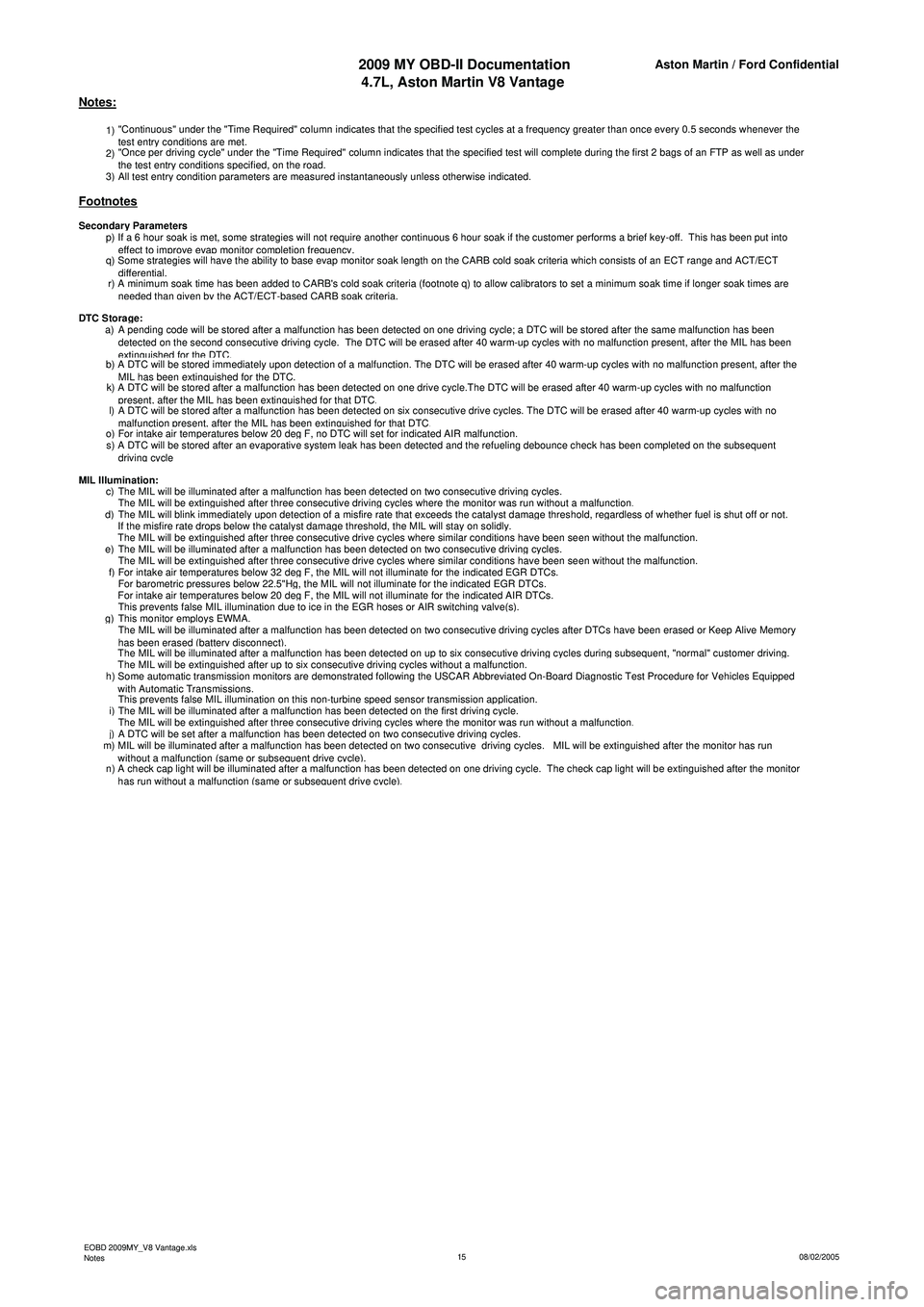
2009 MY OBD-II Documentation4.7L, Aston Martin V8 VantageAston Martin / Ford Confidential
1) "Continuous" under the "Time Required" column indicates that the specified test cycles at a frequency greater than once every 0.5 seconds whenever the
test entry conditions are met.
2) "Once per driving cycle" under the "Time Required" column indicates that the specified test will complete during the first 2 bags of an FTP as well as under
the test entr
y conditions specified, on the road.
3)All test entry condition parameters are measured instantaneously unless otherwise indicated.
p) If a 6 hour soak is met, some strategies will not require another continuous 6 hour soak if the customer performs a brief key-off. This has been put into
effect to improve evap monitor completion frequency.
q) Some strategies will have the ability to base evap monitor soak length on the CARB cold soak criteria which consists of an ECT range and ACT/ECT
differential.
r) A minimum soak time has been added to CARB's cold soak criteria (footnote q) to allow calibrators to set a minimum soak time if longer soak times are
n
eeded than given by the ACT/ECT-based CARB soak criteria.
a) A pending code will be stored after a malfunction has been detected on one driving cycle; a DTC will be stored after the same malfunction has been detected on the second consecutive driving cycle. The DTC will be erased after 40 warm-up cycles with no malfunction present, after the MIL has been
extinguished for the DTC.b) A DTC will be stored immediately upon detection of a malfunction. The DTC will be erased after 40 warm-up cycles with no malfunction present, after the MIL has been extinguished for the DTC.k) A DTC will be stored after a malfunction has been detected on one drive cycle.The DTC will be erased after 40 warm-up cycles with no malfunction present, after the MIL has been extinguished for that DTC.l) A DTC will be stored after a malfunction has been detected on six consecutive drive cycles. The DTC will be erased after 40 warm-up cycles with no malfunction present, after the MIL has been extinguished for that DTC.o)For intake air temperatures below 20 deg F, no DTC will set for indicated AIR malfunction.
s) A DTC will be stored after an evaporative system leak has been detected and the refueling debounce check has been completed on the subsequent
driving cycle
c)The MIL will be illuminated after a malfunction has been detected on two consecutive driving cycles.
The MIL will be extinguished after three consecutive driving cycles where the monitor was run without a malfunction.d)The MIL will blink immediately upon detection of a misfire rate that exceeds the catalyst damage threshold, regardless of whether fuel is shut off or not.
If the misfire rate drops below the catalyst damage threshold, the MIL will stay on solidly.
The MIL will be extinguished after three consecutive drive cycles where similar conditions have been seen without the malfunction.e)The MIL will be illuminated after a malfunction has been detected on two consecutive driving cycles.
The MIL will be extinguished after three consecutive drive cycles where similar conditions have been seen without the malfunction.f)For intake air temperatures below 32 deg F, the MIL will not illuminate for the indicated EGR DTCs.
For barometric pressures below 22.5"Hg, the MIL will not illuminate for the indicated EGR DTCs.
For intake air temperatures below 20 deg F, the MIL will not illuminate for the indicated AIR DTCs.
This prevents false MIL illumination due to ice in the EGR hoses or AIR switching valve(s).g)This monitor employs EWMA.
The MIL will be illuminated after a malfunction has been detected on two consecutive driving cycles after DTCs have been erased or Keep Alive Memory
h
as been erased (battery disconnect).
The MIL will be illuminated after a malfunction has been detected on up to six consecutive driving cycles during subsequent, "normal" customer driving.
The MIL will be extinguished after up to six consecutive driving cycles without a malfunction.
h) Some automatic transmission monitors are demonstrated following the USCAR Abbreviated On-Board Diagnostic Test Procedure for Vehicles Equipped
wi
th Automatic Transmissions.
This prevents false MIL illumination on this non-turbine speed sensor transmission application.
i)The MIL will be illuminated after a malfunction has been detected on the first driving cycle.
The MIL will be extinguished after three consecutive driving cycles where the monitor was run without a malfunction.j)A DTC will be set after a malfunction has been detected on two consecutive driving cycles.
m) MIL will be illuminated after a malfunction has been detected on two consecutive driving cycles. MIL will be extinguished after the monitor has run
wi
thout a malfunction (same or subsequent drive cycle).
n) A check cap light will be illuminated after a malfunction has been detected on one driving cycle. The check cap light will be extinguished after the monitor
h
as run without a malfunction (same or subsequent drive cycle).
MIL Illumination:
Notes:
Footnotes
Secondary Parameters
DTC Stora
ge:
EOBD 2009MY_V8 Vantage.xls
Notes 08/02/2005
15
Page 930 of 947

Aston Martin V12 Family
2009 MY V12 Family EOBDincl. V12 Vantage
Aston Martin/Ford Confidential
Notes:
1) "Continuous" under the "Time Required" column indicates that the specified test cycles at a frequency greater than once every 0.5
seconds whenever the test entr
y conditions are met.
2) "Once per driving cycle" under the "Time Required" column indicates that the specified test will complete during the first 2 bags of an
FTP as well as under the test entry conditions s
pecified
, on the road.
3
)All test entr
y condition
parameters are measured instantaneousl
y unless otherwise indicated.
Footnotes:Secondar
y Parameters:
p) If a 6 hour soak is met, some strategies will not require another continuous 6 hour soak if the customer performs a brief key-off. This
has been put into effect to im
prove eva
p monitor com
pletion fre
quenc
y.
q) Some strategies will have the ability to base evap monitor soak length on the CARB cold soak criteria which consists of an ECT range
and ACT/ECT differential.
r) A minimum soak time has been added to CARB's cold soak criteria (footnote q) to allow calibrators to set a minimum soak time if
lon
ger soak times are needed than
given b
y the ACT/ECT-based CARB soak criteria.
DTC Stora
ge:
a) A pending code will be stored after a malfunction has been detected on one driving cycle; a DTC will be stored after the same
malfunction has been detected on the second consecutive drivin
g cycle. The DTC will be erased after 40 warm-u
p cycles with no ma
b) A DTC will be stored immediately upon detection of a malfunction. The DTC will be erased after 40 warm-up cycles with no malfunction
present
, after the MIL has been extin
guished for the DTC.
k) A DTC will be stored after a malfunction has been detected on one drive cycle.The DTC will be erased after 40 warm-up cycles with no
malfunction
present
, after the MIL has been extin
guished for that DTC.
l) A DTC will be stored after a malfunction has been detected on six consecutive drive cycles. The DTC will be erased after 40 warm-up
c
ycles with no malfunction
present
, after the MIL has been extin
guished for that DTC.
o
)For intake air tem
peratures below 20 de
g F, no DTC will set for indicated AIR malfunction.
s) A pending code will be stored after a malfunction has been detected on upto the 6th trip depending on the size of the fault deviation; a
DTC will be stored after the same malfunction has been detected on a second driving cycle. The DTC will be erased after 40 warm-up
cycles with no malfunction. This monitor employs EVMA.
MIL Illumination:c)The MIL will be illuminated after a malfunction has been detected on two consecutive drivin
g cycles.
The MIL will be extin
guished after three consecutive drivin
g cycles where the monitor was run without a malfunction.
d) The MIL will blink immediately upon detection of a misfire rate that exceeds the catalyst damage threshold, regardless of whether fuel
is shut off or not.
If the misfire rate dro
ps below the catal
yst dama
ge threshold
, the MIL will sta
y on solidl
y.
The MIL will be extin
guished after three consecutive drive c
ycles where similar conditions have been seen without the malfunction.
e
)The MIL will be illuminated after a malfunction has been detected on two consecutive drivin
g cycles.
19
Page 939 of 947
Service Bulletin SB-17-0298
February 2009 Page 2 of 5
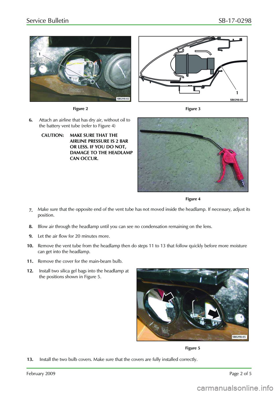
Figure 2
1
SB0298-03
Figure 3
6. Attach an airline that has dry air, without oil to
the battery vent tube (refer to Figure 4)
CAUTION: MAKE SURE THAT THE
AIRLINE PRESSURE IS 2 BAR
OR LESS. IF YOU DO NOT,
DAMAGE TO THE HEADLAMP
CAN OCCUR.
Figure 4
7. Make sure that the opposite end of the vent tube has
not moved inside the headlamp. If necessary, adjust its
position.
8. Blow air through the headlamp until you can see no condensation remaining on the lens.
9. Let the air flow for 20 minutes more.
10. Remove the vent tube from the headlamp then do st eps 11 to 13 that follow quickly before more moisture
can get into the headlamp.
11. Remove the cover for the main-beam bulb.
12. Install two silica gel bags into the headlamp at
the positions shown in Figure 5.
Figure 5
13. Install the two bulb covers. Make sure that the covers are fully installed correctly.
Page 941 of 947
Service Bulletin SB-17-0298
February 2009 Page 4 of 5
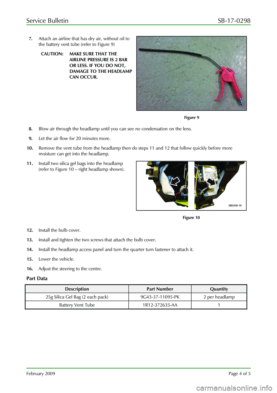
7. Attach an airline that has dry air, without oil to
the battery vent tube (refer to Figure 9)
CAUTION: MAKE SURE THAT THE
AIRLINE PRESSURE IS 2 BAR
OR LESS. IF YOU DO NOT,
DAMAGE TO THE HEADLAMP
CAN OCCUR.
Figure 9
8. Blow air through the headlamp until you can see no condensation on the lens.
9. Let the air flow for 20 minutes more.
10. Remove the vent tube from the headlamp then do steps 11 and 12 that follow quickly before more
moisture can get into the headlamp.
11. Install two silica gel bags into the headlamp
(refer to Figure 10 – right headlamp shown).
Figure 10
12. Install the bulb cover.
13. Install and tighten the two screws that attach the bulb cover.
14. Install the headlamp access panel and turn the quarter turn fastener to attach it.
15. Lower the vehicle.
16. Adjust the steering to the centre.
Part Data
Description Part Number Quantity
25g Silica Gel Bag (2 each pa ck) 9G43-37-11095-PK 2 per headlamp
Battery Vent Tube 1R12-372635-AA 1