compression ratio ASTON MARTIN V8 VANTAGE 2010 Workshop Manual
[x] Cancel search | Manufacturer: ASTON MARTIN, Model Year: 2010, Model line: V8 VANTAGE, Model: ASTON MARTIN V8 VANTAGE 2010Pages: 947, PDF Size: 43.21 MB
Page 436 of 947

Rear Suspension (04.02)
Suspension (04.00)4-2-2 Workshop Manual May 2007
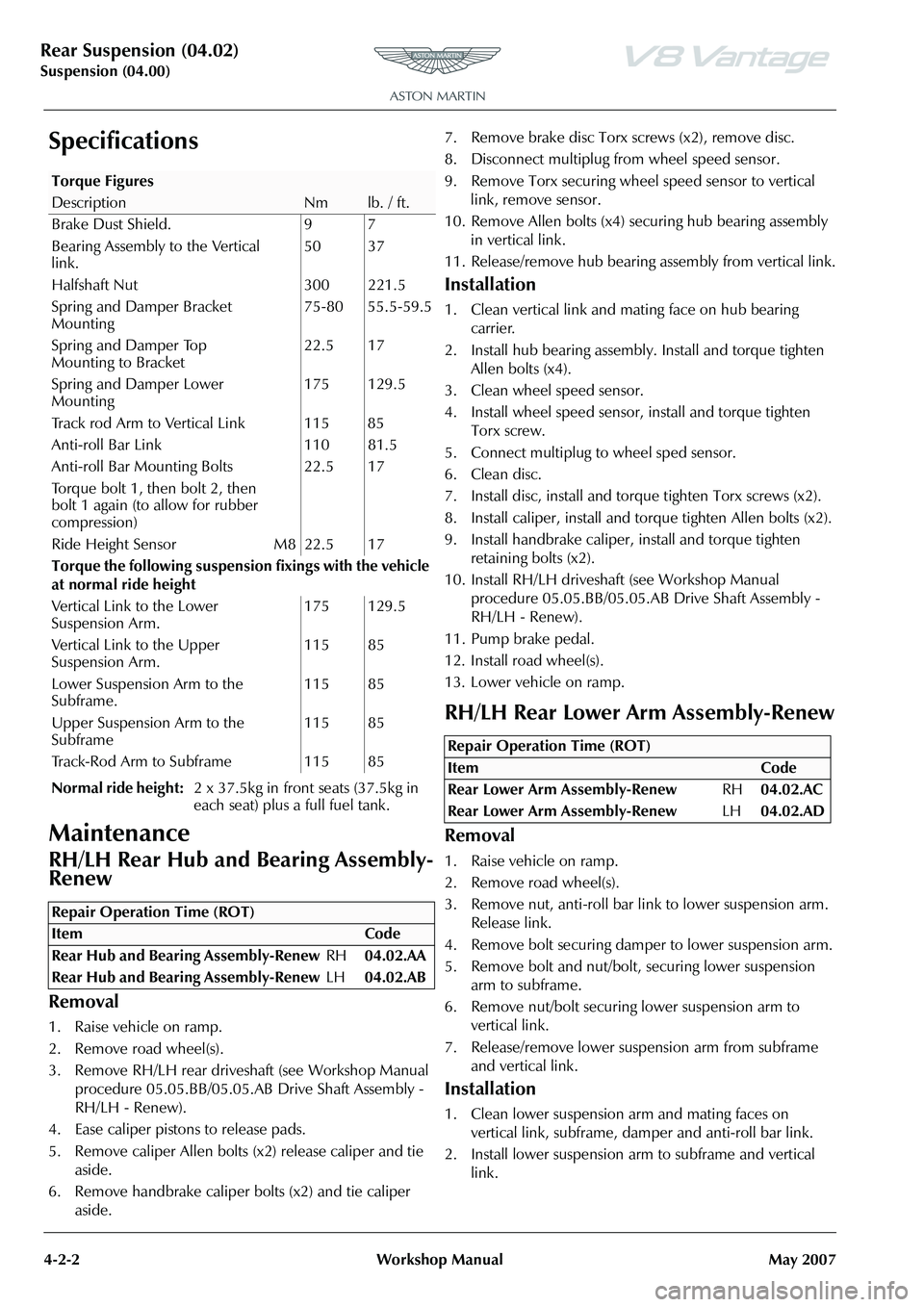
Specifications
Maintenance
RH/LH Rear Hub and Bearing Assembly-
Renew
Removal
1. Raise vehicle on ramp.
2. Remove road wheel(s).
3. Remove RH/LH rear drivesha ft (see Workshop Manual
procedure 05.05.BB/05.05.AB Drive Shaft Assembly -
RH/LH - Renew).
4. Ease caliper pistons to release pads.
5. Remove caliper Allen bolts (x2) release caliper and tie aside.
6. Remove handbrake caliper bolts (x2) and tie caliper aside. 7. Remove brake disc Torx screws (x2), remove disc.
8. Disconnect multiplug fr
om wheel speed sensor.
9. Remove Torx securing wheel speed sensor to vertical link, remove sensor.
10. Remove Allen bolts (x4) se curing hub bearing assembly
in vertical link.
11. Release/remove hub bearing a ssembly from vertical link.
Installation
1. Clean vertical link and mating face on hub bearing
carrier.
2. Install hub bearing assembly. Install and torque tighten Allen bolts (x4).
3. Clean wheel speed sensor.
4. Install wheel speed sensor, install and torque tighten Torx screw.
5. Connect multiplug to wheel sped sensor.
6. Clean disc.
7. Install disc, install and torq ue tighten Torx screws (x2).
8. Install caliper, install and torque tighten Allen bolts (x2).
9. Install handbrake caliper, install and torque tighten
retaining bolts (x2).
10. Install RH/LH driveshaft (see Workshop Manual
procedure 05.05.BB/05.05.AB Drive Shaft Assembly -
RH/LH - Renew).
11. Pump brake pedal.
12. Install road wheel(s).
13. Lower vehicle on ramp.
RH/LH Rear Lower Arm Assembly-Renew
Removal
1. Raise vehicle on ramp.
2. Remove road wheel(s).
3. Remove nut, anti-roll bar li nk to lower suspension arm.
Release link.
4. Remove bolt securing damper to lower suspension arm.
5. Remove bolt and nut/bolt, securing lower suspension arm to subframe.
6. Remove nut/bolt securing lower suspension arm to
vertical link.
7. Release/remove lower suspension arm from subframe and vertical link.
Installation
1. Clean lower suspension arm and mating faces on vertical link, subframe, damper and anti-roll bar link.
2. Install lower suspension ar m to subframe and vertical
link.
Torque Figures
DescriptionNmlb. / ft.
Brake Dust Shield. 9 7
Bearing Assembly to the Vertical
link. 50 37
Halfshaft Nut 300 221.5
Spring and Damper Bracket
Mounting 75-80 55.5-59.5
Spring and Damper Top
Mounting to Bracket 22.5 17
Spring and Damper Lower
Mounting 175 129.5
Track rod Arm to Vertical Link 115 85
Anti-roll Bar Link 110 81.5
Anti-roll Bar Mounting Bolts
Torque bolt 1, then bolt 2, then
bolt 1 again (to allow for rubber
compression) 22.5 17
Ride Height Sensor M8 22.5 17
Torque the following suspensi on fixings with the vehicle
at normal ride height
Vertical Link to the Lower
Suspension Arm. 175 129.5
Vertical Link to the Upper
Suspension Arm. 115 85
Lower Suspension Arm to the
Subframe. 115 85
Upper Suspension Arm to the
Subframe 115 85
Track-Rod Arm to Subframe 115 85
Normal ride height: 2 x 37.5kg in front seats (37.5kg in
each seat) plus a full fuel tank.
Repair Operation Time (ROT)
Repair Operation Time (ROT)
ItemCode
Rear Lower Arm Assembly-Renew RH04.02.AC
Rear Lower Arm Assembly-Renew LH04.02.AD
Page 871 of 947

AML EOBD System Operation Summary
Rory O’Curry Aston Martin Lagonda CONFIDENTIAL 1 May 2009
[email protected] AML EOBD Monitors 07 ROC.doc Page 25 of 43
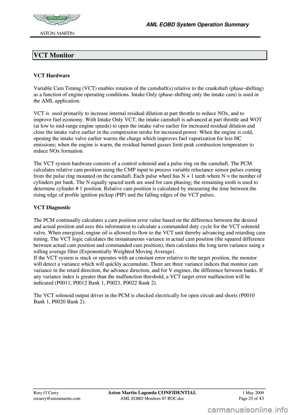
VCT Monitor
Variable Cam Timing System Monitor
VCT Hardware
Variable Cam Timing (VCT) enables rotation of the camshaft(s) relative to the crankshaft (phase-shifting)
as a function of engine operating conditions. Intake Only (phase-shifting only the intake cam) is used in
the AML application.
VCT is used primarily to increase internal residua l dilution at part throttle to reduce NOx, and to
improve fuel economy. With Intake Only VCT, the in take camshaft is advanced at part throttle and WOT
(at low to mid-range engine speeds) to open the in take valve earlier for increased residual dilution and
close the intake valve earlier in the compression stroke for increased power. When the engine is cold,
opening the intake valve earlier warms the charge which improves fuel vaporization for less HC
emissions; when the engine is warm, the residua l burned gasses limit peak combustion temperature to
reduce NOx formation.
The VCT system hardware consists of a contro l solenoid and a pulse ring on the camshaft. The PCM
calculates relative cam position using the CMP input to process variable reluctance sensor pulses coming
from the pulse ring mounted on the camshaft. Each pul se wheel has N + 1 teeth where N = the number of
cylinders per bank. The N equally spaced teeth are used for cam phasing; the remaining tooth is used to
determine cylinder # 1 position. Relative cam position is calculated by measuring the time between the
rising edge of profile ignition pickup (PIP ) and the falling edges of the VCT pulses.
VCT Diagnostic
The PCM continually calculates a cam position error value based on the difference between the desired
and actual position and uses this information to cal culate a commanded duty cycle for the VCT solenoid
valve. When energized, engine oil is allowed to flow to the VCT unit thereby advancing and retarding cam
timing. The VCT logic calculates the instantaneous va riance in actual cam position (the squared difference
between actual cam position and commanded cam position), then calculates the long term variance using a
rolling average filter (Exponentially Weighted Moving Average).
If the VCT system is stuck or operates with an consta nt error relative to the target position, the monitor
will detect a variance which will quickly accumulate. There are three variance indices that monitor cam
variance in the retard direction, the advance directi on, and for V engines, the difference between banks. If
any variance index is greater than the malfunction threshold, a VCT target error malfunction will be
indicated (P0011, P0012 Bank 1, P0021, P0022 Bank 2).
The VCT solenoid output driver in the PCM is check ed electrically for open circuit and shorts (P0010
Bank 1, P0020 Bank 2).
VCT Monitor Operation:
Page 873 of 947

AML EOBD System Operation Summary
Rory O’Curry Aston Martin Lagonda CONFIDENTIAL 1 May 2009
[email protected] AML EOBD Monitors 07 ROC.doc Page 27 of 43
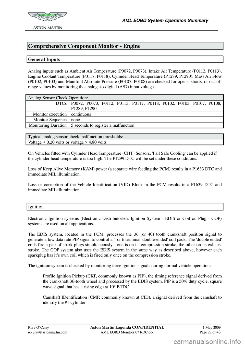
Comprehensive Component Monitor - Engine
General Inputs
Analog inputs such as Ambient Air Temperature (P0072, P0073), Intake Air Temperature (P0112, P0113),
Engine Coolant Temperature (P0117, P0118), Cylinder Head Temperature (P1289, P1290), Mass Air Flow
(P0102, P0103) and Manifold Absolute Pressure (P0107, P0108) are checked for opens, shorts, or out-of-
range values by monitoring the analog -to-digital (A/D) input voltage.
Analog Sensor Check Operation:
DTCs P0072, P0073, P0112, P0113, P0117, P0118, P0102, P0103, P0107, P0108,
P1289, P1290
Monitor execution continuous
Monitor Sequence none
Monitoring Duration 5 seconds to register a malfunction
Typical analog sensor check malfunction thresholds:
Voltage < 0.20 volts or voltage > 4.80 volts
On Vehicles fitted with Cylinder Head Temperature (CHT ) Sensors, 'Fail Safe Cooling' can be applied if
the cylinder head temperature is too high. The P1299 DTC will be set under these conditions.
Loss of Keep Alive Memory (KAM) power (a separate wire feeding the PCM) results in a P1633 DTC and
immediate MIL illumination.
Loss or corruption of the Vehicle Identification (VID) Block in the PCM results in a P1639 DTC and
immediate MIL illumination.
Ignition
Electronic Ignition systems (Electronic Distributorless Ignition System - EDIS or Coil on Plug - COP)
systems are used on all applications.
The EDIS system, located in the PCM, processes the 36 (or 40) tooth crankshaft position signal to
generate a low data rate PIP signal to control a 4 or 6 terminal 'double-ended' coil pack. The 'double ended'
coils fire a pair of spark plugs simultaneously - one is on its compression stroke, the other on its exhaust
stroke. The COP system also uses the EDIS system in the same way as described above, however each
sparkplug has it’s own coil which is fired only once on the compression stroke.
The ignition system is checked by monitoring three ignition signals during normal vehicle operation:
Profile Ignition Pickup (CKP, commonly known as PIP), the timing reference signal derived from the crankshaft 36-tooth wheel and processed by the EDIS system. PIP is a 50% duty cycle, square
wave signal that has a rising edge at 10 ° BTDC.
Camshaft IDentification (CMP, commonly known at CID), a signal derived from the camshaft to identify the #1 cylinder