check engine ASTON MARTIN V8 VANTAGE 2010 Service Manual
[x] Cancel search | Manufacturer: ASTON MARTIN, Model Year: 2010, Model line: V8 VANTAGE, Model: ASTON MARTIN V8 VANTAGE 2010Pages: 947, PDF Size: 43.21 MB
Page 605 of 947
Power Steering (11.02)
Steering (11.00)11-2-2 Workshop Manual Issue 5, January 2010
Maintenance
Power Steering System - Bleed
Procedure
1. Do a check of the fluid level in the PAS fluid reservoir. Add fluid if necessary.
2. Start the engine and let it idle for 20 seconds.
3. Operate the steering fully to the left and then the right through three cycles.
4. Stop the engine.
5. Wait for five minutes then do a check of the fluid level in the PAS fluid reservoir again.
6. Add fluid if necessary.
7. Install the PAS fluid reservoir cap.
Power Steering Pump-Renew
Removal
1. Remove A/C compressor (see Workshop Manual procedure 03.05.BE Compre ssor - Air Conditioning -
Renew).
2. Coolant drain (see Workshop Manual procedure 03.03.AD Coolant - Drain & Refill).
3. Remove PAS fluid from reservoir.
4. Disconnect HP union from PAS pump pipe.
5. Remove bolt P-clip suction hose to body.
6. Remove bolt (x1) HP pump pipe to engine.
7. Remove bolts (x3) PAS pump to engine.
8. Disconnect bottom hose and move aside.
9. Unclip (x1) harness from cylinder head for access.
10. Manouvre pump forward and up.
11. Disconnect suction hose (cut off clip) and remove pump.
12. Remove HP union pipe from pump (mark position on
pump).
Installation
1. Install HP union pipe to pump (align correctly), fit new O-ring.
2. Install pump to vehicle connect suction pipe to PAS pump, align timing marks and fit new clip.
3. Manouvre pump into position.
4. Install bolts (x3) PAS pump to engine (torque).
5. Install bolt (x1) HP pump pipe to engine (torque).
6. Connect bottom hose.
7. Clip (x1) harness from cylinder head for access. 8. Install bolt P-clip suction hose to body (torque).
9. Connect HP union to PAS pump pipe, replace O-ring
(torque).
10. Coolant refill (see Workshop Manual procedure 03.03.AD Coolant - Drain & Refill).
11. Install A/C compressor (see Workshop Manual procedure 03.05.BE Compre ssor - Air Conditioning -
Renew).
12. Top-up PAS fluid.
13. Start and run engine, operate steering lock to lock x2.
14. Top-up PAS fluid.
Power Assisted Steering (PAS) Rack -
Remove and Install
Removal
1. Disconnect the battery ground cable.
2. Remove the front undertray (refer to Workshop Manual Procedure 01.02.NB - Front Undertray).
3. Remove the front wheels and tyres (refer to Workshop Manual Procedure 04.04.ED - Wheel and Tyre - Pair).
4. Remove the front right side wheel-arch liner (refer to Workshop Manual Procedure 01.02.GB - Front Right
Side Wheel-Arch Liner).
5. Put a container in position under the oil tank to collect oil.
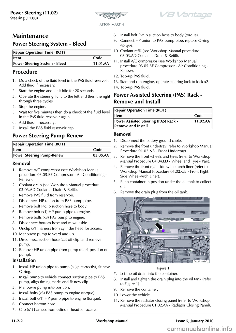
6. Remove the drain plug from the oil tank.
Figure 1
7. Let the oil drain into the container.
8. Install and tighten the drain plug into the oil tank (refer to Figure 1).
9. Remove the container.
10. Lower the vehicle.
11. Remove the radiator closing panel (refer to Workshop Manual Procedure 01.02.AA - Radiator Closing Panel).
Repair Operation Time (ROT)
Repair Operation Time (ROT)
Repair Operation Time (ROT)
ItemCode
Power Assisted Steering (PAS) Rack -
Remove and Install 11.02.AA
Page 614 of 947
Power Steering (11.02)
Steering (11.00)
Issue 5, January 2010 Workshop Manual 11-2-11
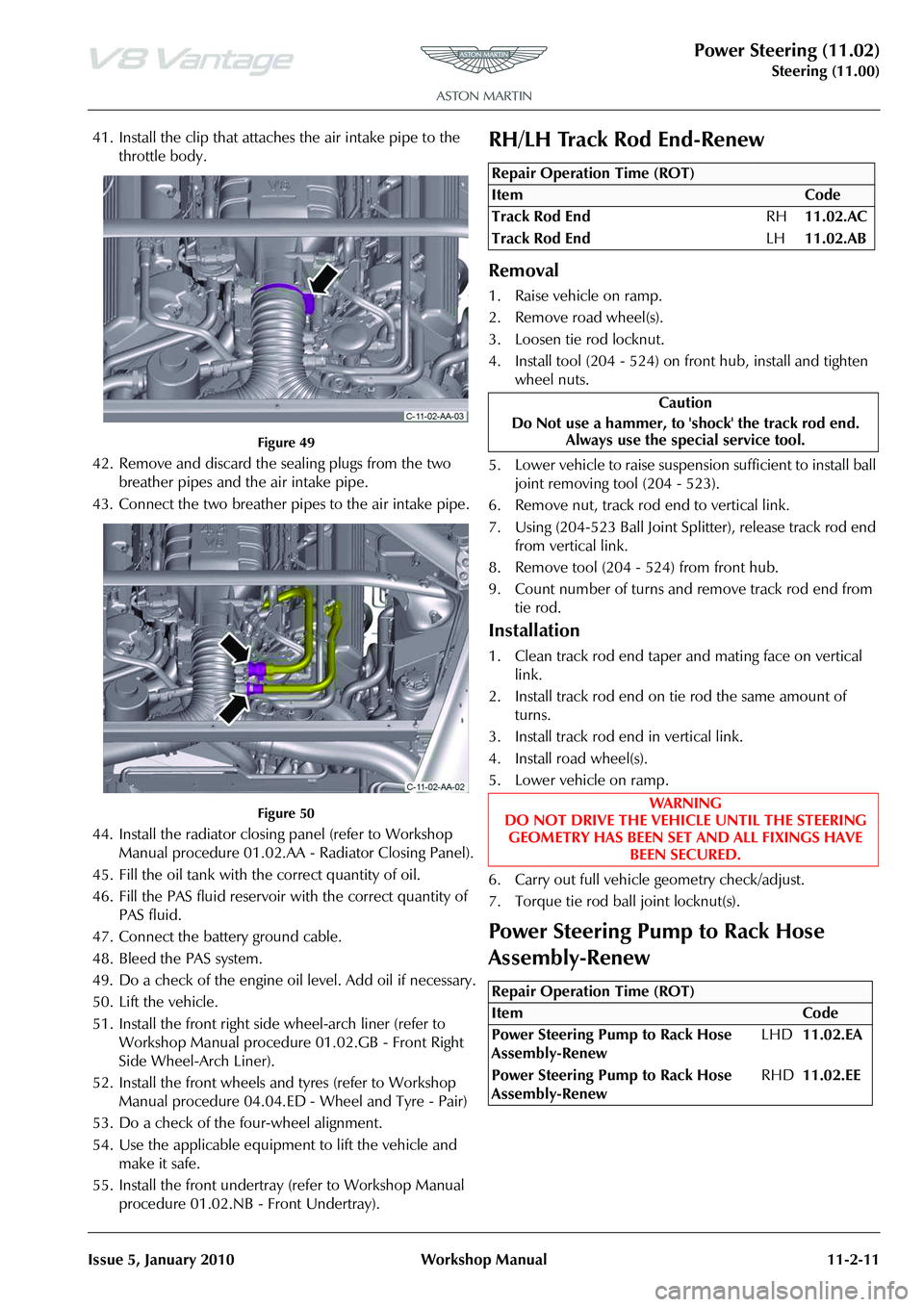
41. Install the clip that attaches the air intake pipe to the throttle body.
Figure 49
42. Remove and discard the sealing plugs from the two breather pipes and the air intake pipe.
43. Connect the two breather pipes to the air intake pipe.
Figure 50
44. Install the radiator closing panel (refer to Workshop Manual procedure 01.02.AA - Radiator Closing Panel).
45. Fill the oil tank with the correct quantity of oil.
46. Fill the PAS fluid reservoir with the correct quantity of
PAS fluid.
47. Connect the battery ground cable.
48. Bleed the PAS system.
49. Do a check of the engine oi l level. Add oil if necessary.
50. Lift the vehicle.
51. Install the front right side wheel-arch liner (refer to Workshop Manual procedure 01.02.GB - Front Right
Side Wheel-Arch Liner).
52. Install the front wheels and tyres (refer to Workshop Manual procedure 04.04.ED - Wheel and Tyre - Pair)
53. Do a check of the four-wheel alignment.
54. Use the applicable equipment to lift the vehicle and make it safe.
55. Install the front undertray (refer to Workshop Manual procedure 01.02.NB - Front Undertray).
RH/LH Track Rod End-Renew
Removal
1. Raise vehicle on ramp.
2. Remove road wheel(s).
3. Loosen tie rod locknut.
4. Install tool (204 - 524) on front hub, install and tighten
wheel nuts.
5. Lower vehicle to raise suspension sufficient to install ball joint removing tool (204 - 523).
6. Remove nut, track rod end to vertical link.
7. Using (204-523 Ball Joint Sp litter), release track rod end
from vertical link.
8. Remove tool (204 - 524) from front hub.
9. Count number of turns and remove track rod end from tie rod.
Installation
1. Clean track rod end taper and mating face on vertical link.
2. Install track rod end on tie rod the same amount of turns.
3. Install track rod end in vertical link.
4. Install road wheel(s).
5. Lower vehicle on ramp.
6. Carry out full vehicle geometry check/adjust.
7. Torque tie rod ball joint locknut(s).
Power Steering Pump to Rack Hose
Assembly-Renew
Repair Operation Time (ROT)
Repair Operation Time (ROT)
Page 644 of 947
Air Conditioning (A/C) System (12.03)
Climate Control (12.00)
May 2007 Workshop Manual 12-3-11
A/C System Testing
Pressure Check
1. Connect the Recovery / Recycling / Recharging unit.
2. Start the engine. Allow to warm up then run at a constant 1,500 rpm.
3. Set the following A/C controls:
• Air Circulation to ‘Recirculate’
• Temperature to ‘Max’ Cold
• Air Flow to ‘Vent’
4. Close all the vehicle doors and windows.
5. Measure the ambient temperature and high / low pressure side reading of Recovery / Recycling /
Recharging unit gauges.
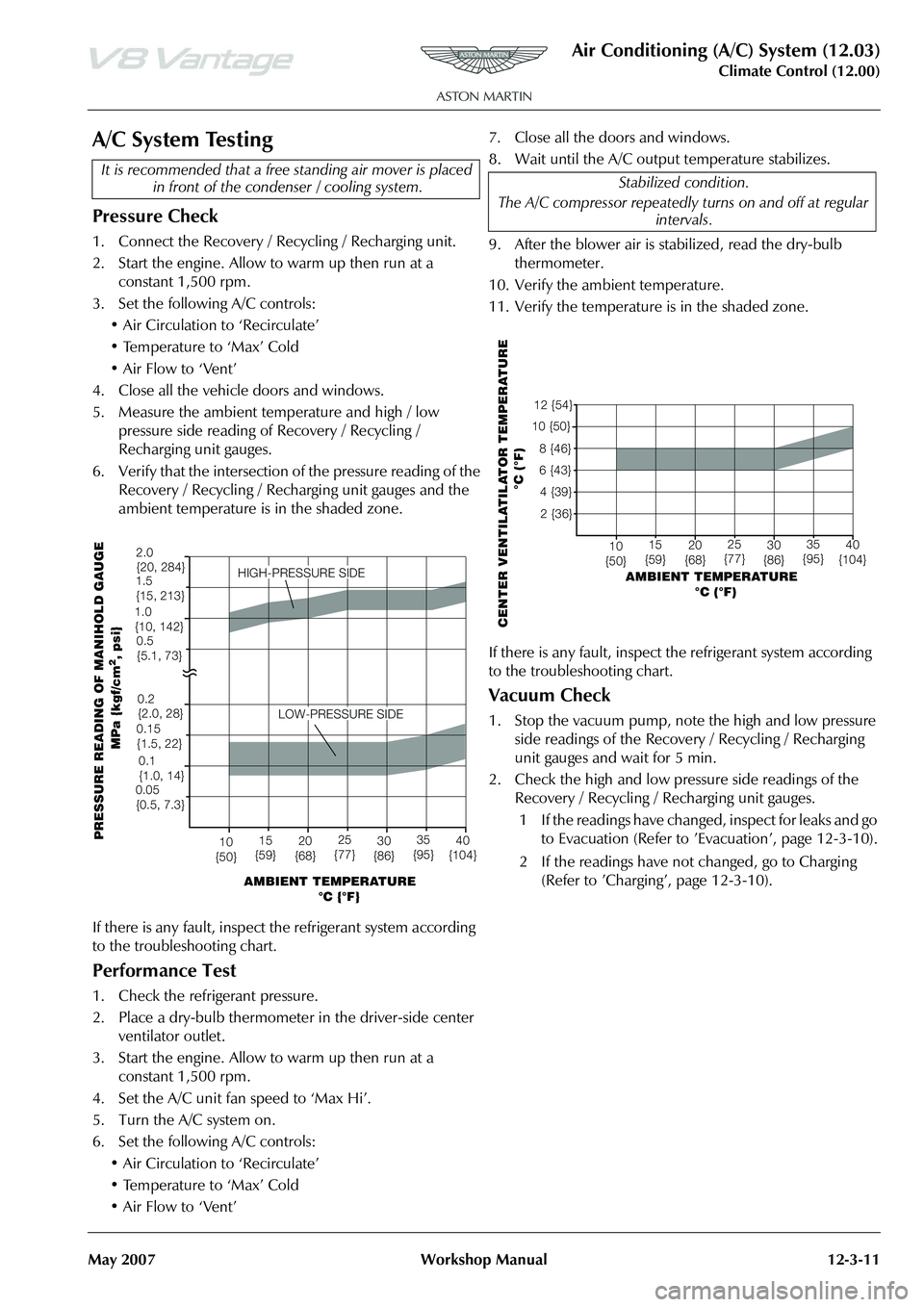
6. Verify that the intersection of the pressure reading of the Recovery / Recycling / Recharging unit gauges and the
ambient temperature is in the shaded zone.
If there is any fault, inspect the refrigerant system according
to the troubleshooting chart.
Performance Test
1. Check the refrigerant pressure.
2. Place a dry-bulb thermometer in the driver-side center ventilator outlet.
3. Start the engine. Allow to warm up then run at a constant 1,500 rpm.
4. Set the A/C unit fan speed to ‘Max Hi’.
5. Turn the A/C system on.
6. Set the following A/C controls: • Air Circulation to ‘Recirculate’
• Temperature to ‘Max’ Cold
• Air Flow to ‘Vent’ 7. Close all the doors and windows.
8. Wait until the A/C output temperature stabilizes.
9. After the blower air is stabilized, read the dry-bulb
thermometer.
10. Verify the ambient temperature.
11. Verify the temperature is in the shaded zone.
If there is any fault, inspect the refrigerant system according
to the troubleshooting chart.
Vacuum Check
1. Stop the vacuum pump, note the high and low pressure side readings of the Recovery / Recycling / Recharging
unit gauges and wait for 5 min.
2. Check the high and low pressure side readings of the Recovery / Recycling / Recharging unit gauges.
1 If the readings have changed, inspect for leaks and go to Evacuation (Refer to ’E vacuation’, page 12-3-10).
2 If the readings have not changed, go to Charging (Refer to ’Charging’, page 12-3-10).
It is recommended th
at a free standing air mover is placed
in front of the conden ser / cooling system.
AMBIENT TEMPERATURE
°C {°F}
10
{50} 15
{59} 20
{68} 25
{77} 30
{86} 35
{95} 40
{104}
LOW-PRESSURE SIDE
HIGH-PRESSURE SIDE
PRESSURE READING OF MANIHOLD GAUGE
MPa {kgf/cm
2, psi}
2.0
{20, 284}
1.5
{15, 213}
1.0
{10, 142}
0.2
{2.0, 28}0.1
{1.0, 14}
0.15
{1.5, 22}
0.05
{0.5, 7.3} 0.5
{5.1, 73}
Stabilized condition.
The A/C compressor repeatedly turns on and off at regular intervals.
AMBIENT TEMPERATURE
°C (°F)
CENTER VENTILATILATOR TEMPERATURE
°C (°F)
12 {54}
10 {50}
8 {46}
6 {43}4 {39} 2 {36}
10
{50} 15
{59} 20
{68} 25
{77} 30
{86} 35
{95} 40
{104}
Page 645 of 947
Air Conditioning (A/C) System (12.03)
Climate Control (12.00)
12-3-12 Workshop Manual May 2007
Leaks
Faults associated with low refrigerant charge weight and low pressure may be caused by leakage. Leaks traced to
mechanical connections may be caused by torque relaxation or joint face contamination. Evidence of oil around such
areas is an indicator of leakage.
Leak Detection
Fluorescent Tracer Dye - A fluorescent tracer dye is incorporated into th e refrigeration system and can be checked for
non-apparent leaks by scanning with a high intensity ultraviolet lamp. The location of leaks can be pinpointed by the bright
yellow glow of the tracer dye.
Automatic Refrigerant Leak Detector - (various manufacturers) Hand-held, portable, battery operated leak detector.
Place in and around A/C system to detect refrigerant leaks.
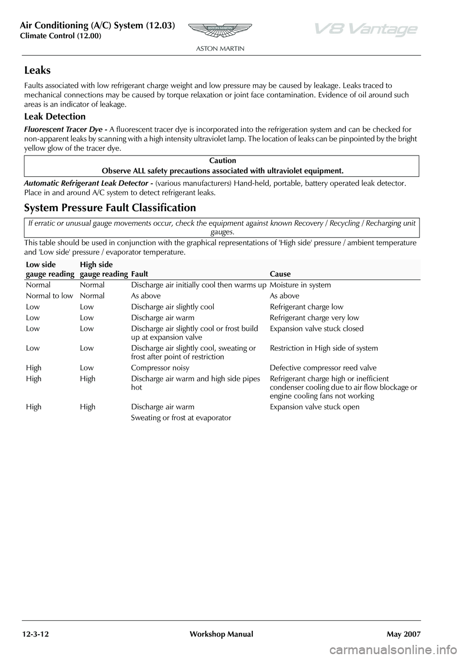
System Pressure Fault Classification
This table should be used in conjunction with the graphical representations of 'High side' pressure / ambient temperature
and 'Low side' pressure / evaporator temperature. Caution
Observe ALL safety precautions associ ated with ultraviolet equipment.
If erratic or unusual gauge movements occur, check the equipment against known Recovery / Recycling / Recharging unit
gauges.
Low side
gauge readingHigh side
gauge reading
Fault
Cause
Normal Normal Discharge air initially c ool then warms up Moisture in system
Normal to low Normal As above As above
Low Low Discharge air slightly cool Refrigerant charge low
Low Low Discharge air warm Refrigerant charge very low
Low Low Discharge air slightly cool or frost build up at expansion valve Expansion valve stuck closed
Low Low Discharge air slightly cool, sweating or frost after point of restriction Restriction in High side of system
High Low Compressor noisy Defective compressor reed valve
High High Discharge air warm and high side pipes hot Refrigerant charge high or inefficient
condenser cooling due to air flow blockage or
engine cooling fans not working
High High Discharge air warm
Sweating or frost at evaporator Expansion valve stuck open
Page 654 of 947
Instrument Cluster (13.01)
Information, Gauge and Warning (13.00)
May 2007 Workshop Manual 13-1-3
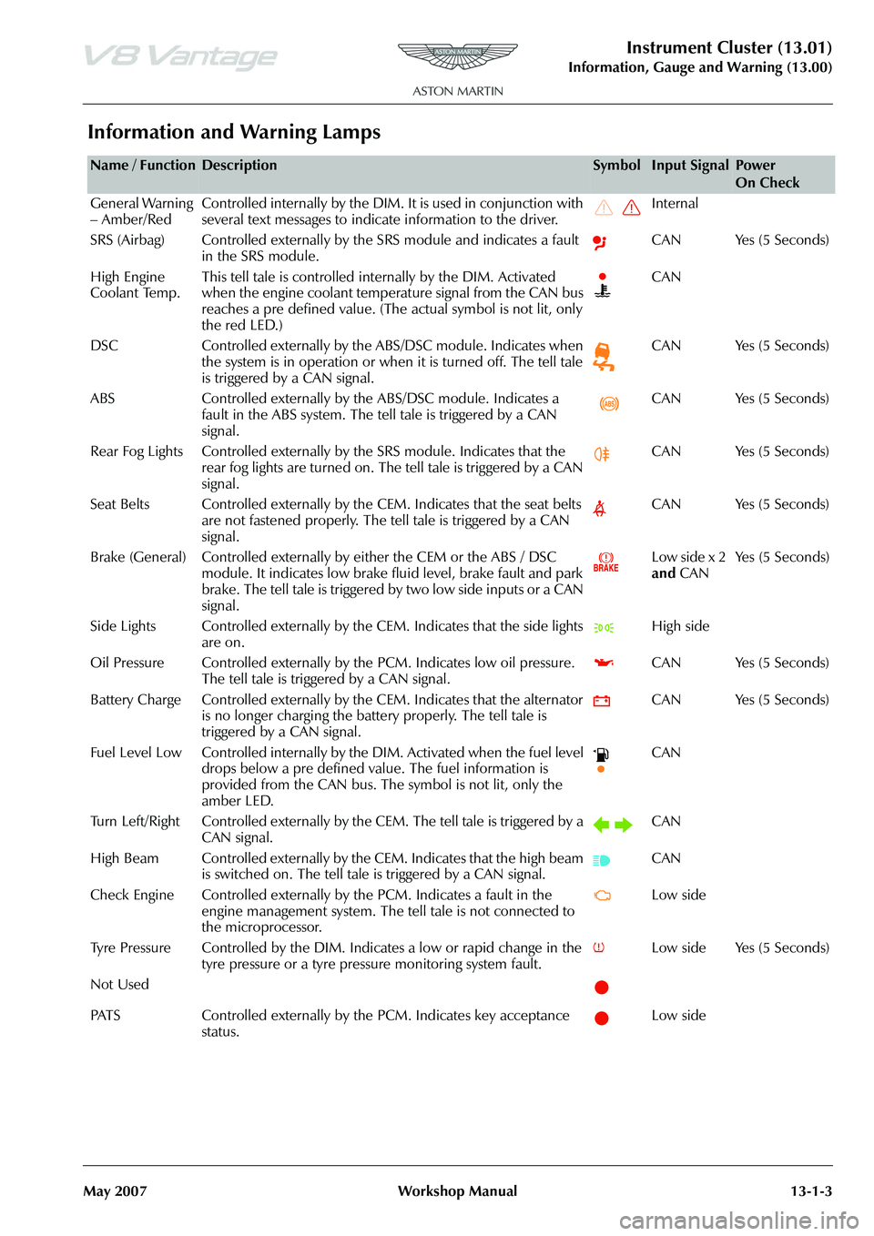
Information and Warning Lamps
Name / FunctionDescriptionSymbolInput SignalPower
On Check
General Warning
– Amber/Red Controlled internally by the DIM. It is used in conjunction with
several text messages to indicate information to the driver. Internal
SRS (Airbag) Controlled externally by the SRS module and indicates a fault in the SRS module. CAN Yes (5 Seconds)
High Engine
Coolant Temp. This tell tale is controlled internally by the DIM. Activated
when the engine coolant temperature signal from the CAN bus
reaches a pre defined value. (The
actual symbol is not lit, only
the red LED.) CAN
DSC Controlled externally by the ABS/DSC module. Indicates when the system is in operation or when it is turned off. The tell tale
is triggered by a CAN signal. CAN Yes (5 Seconds)
ABS Controlled externally by th e ABS/DSC module. Indicates a
fault in the ABS system. The tell tale is triggered by a CAN
signal. CAN Yes (5 Seconds)
Rear Fog Lights Controlled externally by the SRS module. Indicates that the
rear fog lights are turned on. The tell tale is triggered by a CAN
signal. CAN Yes (5 Seconds)
Seat Belts Controlled externally by the CEM. Indicates that the seat belts are not fastened properly. The tell tale is triggered by a CAN
signal. CAN Yes (5 Seconds)
Brake (General) Controlled externally by either the CEM or the ABS / DSC module. It indicates low brake fluid level, brake fault and park
brake. The tell tale is triggered by two low side inputs or a CAN
signal. Low side x 2
and
CAN Ye s ( 5 S e c o n d s )
Side Lights Controlled externally by th e CEM. Indicates that the side lights
are on. High side
Oil Pressure Controlled exte rnally by the PCM. Indicates low oil pressure.
The tell tale is triggered by a CAN signal. CAN Yes (5 Seconds)
Battery Charge Controlled externally by th e CEM. Indicates that the alternator
is no longer charging the battery properly. The tell tale is
triggered by a CAN signal. CAN Yes (5 Seconds)
Fuel Level Low Controlled internally by the DIM. Activated when the fuel level drops below a pre defined value. The fuel information is
provided from the CAN bus. The symbol is not lit, only the
amber LED. CAN
Turn Left/Right Controlled externally by th e CEM. The tell tale is triggered by a
CAN signal. CAN
High Beam Controlled externally by the CEM. Indicates that the high beam is switched on. The tell tale is triggered by a CAN signal. CAN
Check Engine Controlled externally by the PCM. Indicates a fault in the engine management system. The te ll tale is not connected to
the microprocessor. Low side
Tyre Pressure Controlled by the DIM. In dicates a low or rapid change in the
tyre pressure or a tyre pressure monitoring system fault. Low side Yes (5 Seconds)
Not Used
PATS Controlled externally by the PCM. Indicates key acceptance status. Low side
Page 751 of 947
Maintenance Schedules
Appendix & Glossary20-1-12 Workshop Manual May 2007
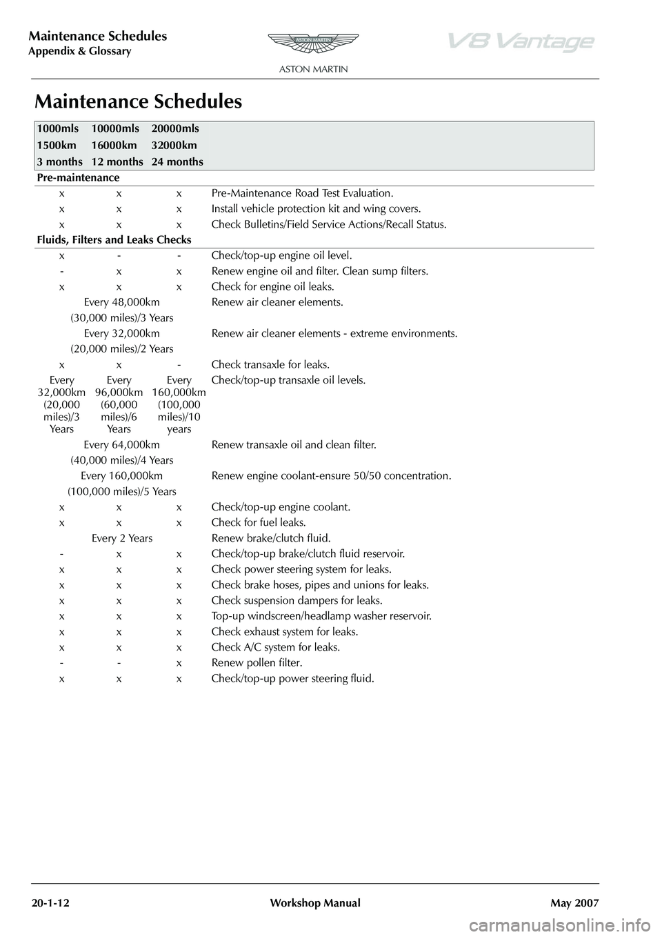
Maintenance Schedules
1000mls
1500km
3 months10000mls
16000km
12 months20000mls
32000km
24 months
Pre-maintenance
x x x Pre-Maintenance Road Test Evaluation.
x x x Install vehicle protection kit and wing covers.
x x x Check Bulletins/Field Service Actions/Recall Status.
Fluids, Filters and Leaks Checks x - - Check/top-up engine oil level.- x x Renew engine oil and filter. Clean sump filters.
x x x Check for engine oil leaks. Every 48,000km
(30,000 miles)/3 Years Renew air cleaner elements.
Every 32,000km
(20,000 miles)/2 Years Renew air cleaner elements - extreme environments.
x x - Check transaxle for leaks.
Every
32,000km (20,000
miles)/3 Ye a r s Every
96,000km (60,000
miles)/6 Ye a r s Every
160,000km (100,000
miles)/10 years Check/top-up transaxle oil levels.
Every 64,000km
(40,000 miles)/4 Years Renew transaxle oil and clean filter.
Every 160,000km
(100,000 miles)/5 Years Renew engine coolant-ensure 50/50 concentration.
x x x Check/top-up engine coolant.
x x x Check for fuel leaks. Every 2 Years Renew brake/clutch fluid.
- x x Check/top-up brake/clutch fluid reservoir.
x x x Check power steering system for leaks.
x x x Check brake hoses, pipes and unions for leaks.
x x x Check suspension dampers for leaks.
x x x Top-up windscreen/headlamp washer reservoir.
x x x Check exhaust system for leaks.
x x x Check A/C system for leaks. - - x Renew pollen filter.
x x x Check/top-up power steering fluid.
Page 857 of 947
AML EOBD System Operation Summary
Rory O’Curry Aston Martin Lagonda CONFIDENTIAL 1 May 2009
[email protected] AML EOBD Monitors 07 ROC.doc Page 11 of 43
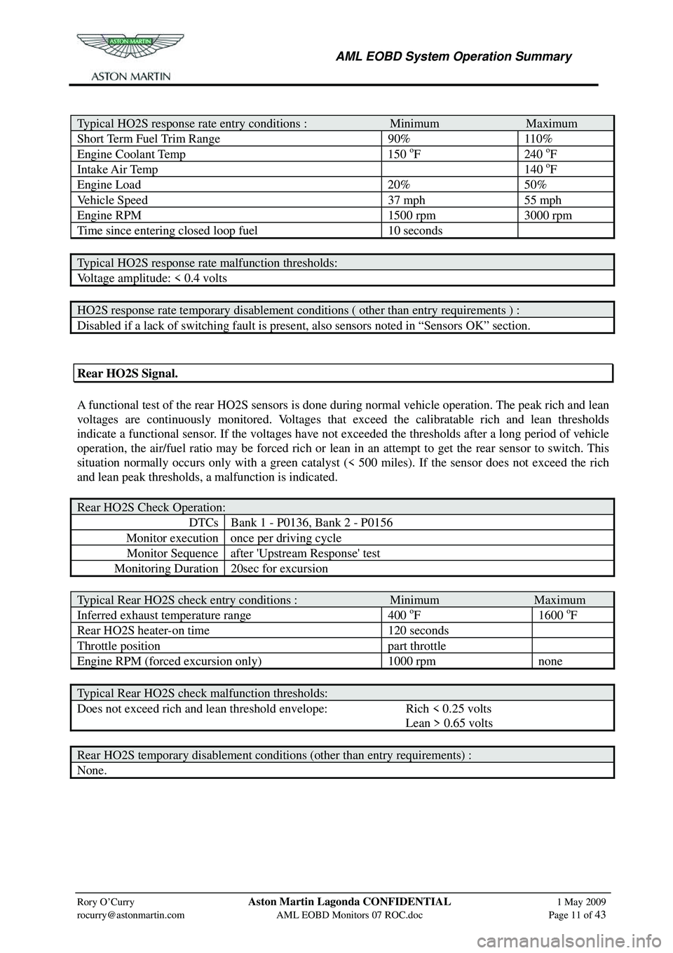
Typical HO2S response rate entry conditions : Minimum Maximum
Short Term Fuel Trim Range 90% 110%
Engine Coolant Temp 150 oF 240 oF
Intake Air Temp 140 oF
Engine Load 20% 50%
Vehicle Speed 37 mph 55 mph
Engine RPM 1500 rpm 3000 rpm
Time since entering closed loop fuel 10 seconds
Typical HO2S response rate malfunction thresholds:
Voltage amplitude: < 0.4 volts
HO2S response rate temporary disablement conditions ( other than entry requirements ) :
Disabled if a lack of switching fault is present, also sensors noted in “Sensors OK” section.
Rear HO2S Signal.
A functional test of the rear HO2S sensors is done dur ing normal vehicle operation. The peak rich and lean
voltages are continuously monitored. Voltages that exceed the calibratable rich and lean thresholds
indicate a functional sensor. If the voltages have not ex ceeded the thresholds after a long period of vehicle
operation, the air/fuel ratio may be forced rich or lean in an attempt to get the rear sensor to switch. This
situation normally occurs only with a green catalyst (< 500 miles). If the sensor does not exceed the rich
and lean peak thresholds, a malfunction is indicated.
Rear HO2S Check Operation:
DTCs Bank 1 - P0136, Bank 2 - P0156
Monitor execution once per driving cycle
Monitor Sequence after 'Upstream Response' test
Monitoring Duration 20sec for excursion
Typical Rear HO2S check entry conditions : Minimum Maximum
Inferred exhaust temperature range 400 oF 1600 oF
Rear HO2S heater-on time 120 seconds
Throttle position part throttle
Engine RPM (forced excursion only) 1000 rpm none
Typical Rear HO2S check malfunction thresholds:
Does not exceed rich and lean threshold envelope: Rich < 0.25 volts
Lean > 0.65 volts
Rear HO2S temporary disablement conditions (other than entry requirements) :
None.
Page 859 of 947
AML EOBD System Operation Summary
Rory O’Curry Aston Martin Lagonda CONFIDENTIAL 1 May 2009
[email protected] AML EOBD Monitors 07 ROC.doc Page 13 of 43
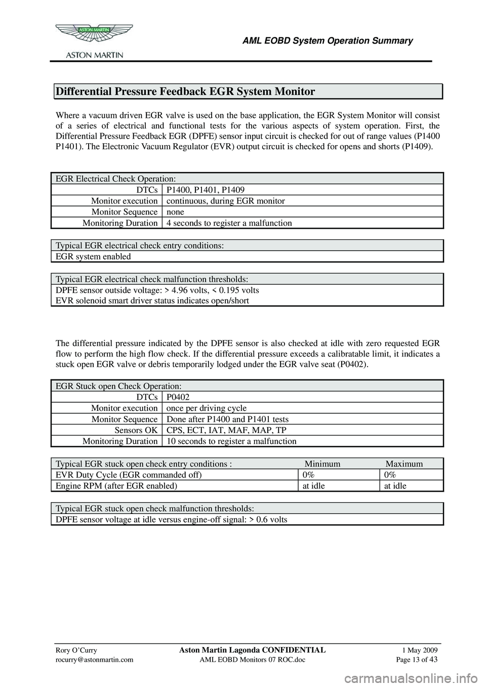
Differential Pressure Feedback EGR System Monitor
Where a vacuum driven EGR valve is used on the base application, the EGR System Monitor will consist
of a series of electrical and functional tests for the various aspects of system operation. First, the
Differential Pressure Feedback EGR (DPFE) sensor input circuit is checked for out of range values (P1400
P1401). The Electronic Vacuum Regulator (EVR) output circuit is checked for opens and shorts (P1409).
EGR Electrical Check Operation:
DTCs P1400, P1401, P1409
Monitor execution continuous, during EGR monitor
Monitor Sequence none
Monitoring Duration 4 seconds to register a malfunction
Typical EGR electrical check entry conditions:
EGR system enabled
Typical EGR electrical check malfunction thresholds:
DPFE sensor outside voltage: > 4.96 volts, < 0.195 volts
EVR solenoid smart driver status indicates open/short
The differential pressure indicated by the DPFE sensor is also checked at idle with zero requested EGR
flow to perform the high flow check. If the differen tial pressure exceeds a calibratable limit, it indicates a
stuck open EGR valve or debris temporar ily lodged under the EGR valve seat (P0402).
EGR Stuck open Check Operation:
DTCs P0402
Monitor execution once per driving cycle
Monitor Sequence Done after P1400 and P1401 tests
Sensors OK CPS, ECT, IAT, MAF, MAP, TP
Monitoring Duration 10 seconds to register a malfunction
Typical EGR stuck open check entry conditions : Minimum Maximum
EVR Duty Cycle (EGR commanded off) 0% 0%
Engine RPM (after EGR enabled) at idle at idle
Typical EGR stuck open check malfunction thresholds:
DPFE sensor voltage at idle versus engine-off signal: > 0.6 volts
Page 860 of 947
AML EOBD System Operation Summary
Rory O’Curry Aston Martin Lagonda CONFIDENTIAL 1 May 2009
[email protected] AML EOBD Monitors 07 ROC.doc Page 14 of 43
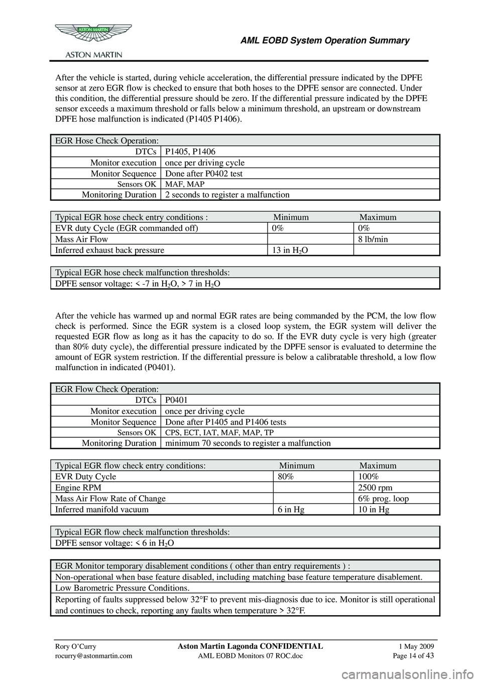
After the vehicle is started, during vehicle acceleration, the differential pressure indicated by the DPFE
sensor at zero EGR flow is checked to ensure that both hoses to the DPFE sensor are connected. Under
this condition, the differential pressure should be zer o. If the differential pressure indicated by the DPFE
sensor exceeds a maximum threshold or falls below a minimum threshold, an upstream or downstream
DPFE hose malfunction is indicated (P1405 P1406).
EGR Hose Check Operation:
DTCs P1405, P1406
Monitor execution once per driving cycle
Monitor Sequence Done after P0402 test
Sensors OK MAF, MAP
Monitoring Duration 2 seconds to register a malfunction
Typical EGR hose check entry conditions : Minimum Maximum
EVR duty Cycle (EGR commanded off) 0% 0%
Mass Air Flow 8 lb/min
Inferred exhaust back pressure 13 in H2O
Typical EGR hose check malfunction thresholds:
DPFE sensor voltage: < -7 in H2O, > 7 in H2O
After the vehicle has warmed up and normal EGR rates are being commanded by the PCM, the low flow
check is performed. Since the EGR system is a closed loop system, the EGR system will deliver the
requested EGR flow as long as it has the capacity to do so. If the EVR duty cycle is very high (greater
than 80% duty cycle), the differential pressure indicated by the DPFE sensor is evaluated to determine the
amount of EGR system restriction. If the differential pr essure is below a calibratable threshold, a low flow
malfunction in indicated (P0401).
EGR Flow Check Operation:
DTCs P0401
Monitor execution once per driving cycle
Monitor Sequence Done after P1405 and P1406 tests
Sensors OK CPS, ECT, IAT, MAF, MAP, TP
Monitoring Duration minimum 70 seconds to register a malfunction
Typical EGR flow check entry conditions: Minimum Maximum
EVR Duty Cycle 80% 100%
Engine RPM 2500 rpm
Mass Air Flow Rate of Change 6% prog. loop
Inferred manifold vacuum 6 in Hg 10 in Hg
Typical EGR flow check malfunction thresholds:
DPFE sensor voltage: < 6 in H2O
EGR Monitor temporary disablement conditions ( other than entry requirements ) :
Non-operational when base feature disabled, including matching base feature temperature disablement.
Low Barometric Pressure Conditions.
Reporting of faults suppressed below 32° F to prevent mis-diagnosis due to ice. Monitor is still operational
and continues to check, reporting any faults when temperature > 32 °F.
Page 869 of 947
AML EOBD System Operation Summary
Rory O’Curry Aston Martin Lagonda CONFIDENTIAL 1 May 2009
[email protected] AML EOBD Monitors 07 ROC.doc Page 23 of 43
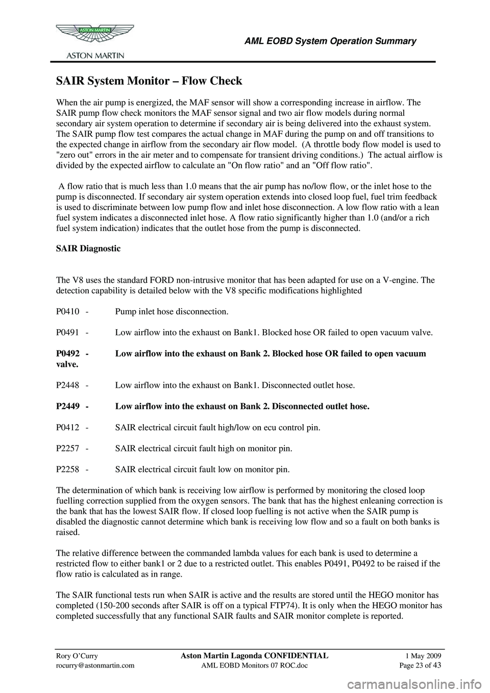
SAIR System Monitor – Flow Check
When the air pump is energized, the MAF sensor will show a corresponding increase in airflow. The
SAIR pump flow check monitors the MAF sensor signal and two air flow models during normal
secondary air system operation to determine if secondary air is being delivered into the exhaust system.
The SAIR pump flow test compares the actual change in MAF during the pump on and off transitions to
the expected change in airflow from the secondary air fl ow model. (A throttle body flow model is used to
"zero out" errors in the air meter and to compensate fo r transient driving conditions.) The actual airflow is
divided by the expected airflow to calculate an "On flow ratio" and an "Off flow ratio".
A flow ratio that is much less than 1.0 means that the air pump has no/low flow, or the inlet hose to the
pump is disconnected. If secondary air system operation ex tends into closed loop fuel, fuel trim feedback
is used to discriminate between low pump flow and in let hose disconnection. A low flow ratio with a lean
fuel system indicates a disconnected inlet hose. A flow ratio significantly higher than 1.0 (and/or a rich
fuel system indication) indicates that th e outlet hose from the pump is disconnected.
SAIR Diagnostic
The V8 uses the standard FORD non-intrusive monitor that has been adapted for use on a V-engine. The
detection capability is detailed below with the V8 specific modifications highlighted
P0410 - Pump inlet hose disconnection.
P0491 - Low airflow into the exhaust on Bank1. Blocked hose OR failed to open vacuum valve.
P0492 - Low airflow into the exhaust on Bank 2. Blocked hose OR failed to open vacuum
valve.
P2448 - Low airflow into the exhaust on Bank1. Disconnected outlet hose.
P2449 - Low airflow into the exhaust on Bank 2. Disconnected outlet hose.
P0412 - SAIR electrical circuit fault high/low on ecu control pin.
P2257 - SAIR electrical circuit fault high on monitor pin.
P2258 - SAIR electrical circuit fault low on monitor pin.
The determination of which bank is receiving low ai rflow is performed by monitoring the closed loop
fuelling correction supplied from the oxygen sensors. The bank that has the highest enleaning correction is
the bank that has the lowest SAIR flow. If closed loop fuelling is not active when the SAIR pump is
disabled the diagnostic cannot determ ine which bank is receiving low flow and so a fault on both banks is
raised.
The relative difference between the commanded lambda values for each bank is used to determine a
restricted flow to either bank1 or 2 due to a restricted outlet. This enables P0491, P0492 to be raised if the
flow ratio is calculated as in range.
The SAIR functional tests run when SAIR is active and the results are stored until the HEGO monitor has
completed (150-200 seconds after SAIR is off on a typical FTP74). It is only when the HEGO monitor has
completed successfully that any functional SAIR fa ults and SAIR monitor complete is reported.