maintenance ASTON MARTIN V8 VANTAGE 2010 Repair Manual
[x] Cancel search | Manufacturer: ASTON MARTIN, Model Year: 2010, Model line: V8 VANTAGE, Model: ASTON MARTIN V8 VANTAGE 2010Pages: 947, PDF Size: 43.21 MB
Page 429 of 947
Front Suspension (04.01)
Suspension (04.00)
November 2008 Workshop Manual 4-1-3
Maintenance
RH/LH Front Hub and Bearing Assembly
- Renew
Removal
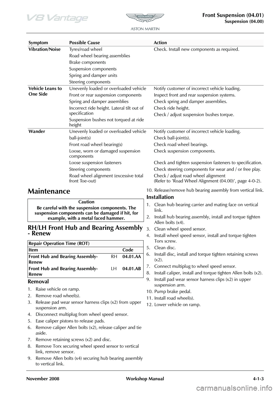
1. Raise vehicle on ramp.
2. Remove road wheel(s).
3. Release pad wear sensor harness clips (x2) from upper suspension arm.
4. Disconnect multiplug from wheel speed sensor.
5. Ease caliper pistons to release pads.
6. Remove caliper Allen bolts (x2), release caliper and tie
aside.
7. Remove retaining screws (x2) and disc.
8. Remove Torx securing wheel speed sensor to vertical link, remove sensor.
9. Remove Allen bolts (x4) securing hub bearing assembly to vertical link. 10. Release/remove hub bearing assembly from vertical link.
Installation
1. Clean hub bearing carrier and mating face on vertical
link.
2. Install hub bearing assembly, install and torque tighten Allen bolts (x4).
3. Clean wheel speed sensor.
4. Install wheel speed sensor, install and torque tighten Torx screw.
5. Clean disc.
6. Install disc, install and torque tighten retaining screws (x2).
7. Connect multiplug to wheel speed sensor.
8. Install caliper, install and to rque tighten Allen bolts (x2).
9. Install pad wear sensor harness clips (x2) in upper suspension arm.
10. Pump brake pedal.
11. Install road wheel(s).
12. Lower vehicle on ramp.
Vibration/Noise
Tyres/road wheel
Road wheel bearing assemblies
Brake components
Suspension components
Spring and damper units
Steering components Check. Install new components as required.
Vehicle Leans to
One Side Unevenly loaded or overloaded vehicle Notif
y customer of incorrect vehicle loading .
Front or rear suspension components Inspect front and rear suspension systems.
Spring and damper assemblies Check spring and damper assemblies.
Incorrect ride height. Lateral tilt out of
specification
Suspension bushes not torqued at ride
height Check ride height.
Check / adjust suspension bushes torque.
Wander Unevenly loaded or overloaded vehicle Notif y customer of incorrect vehicle loading .
ball-joint(s) Check ball-joint(s).
Front road wheel bearing(s) Check road wheel bearings.
Loose, worn or damaged suspension
components Check suspension components.
Loose suspension fasteners Check and tighten suspension fasteners to specification.
Steering components Check steering components for wear and / or free play.
Road wheel alignment (excessive total
front Toe-out) Check / adjust road wheel alignment
(Refer to ’Road Wheel Alignment (04.00)’, page 4-0-2).
SymptomPossible CauseAction
Caution
Be careful with the suspension components. The
suspension components can be damaged if hit, for example, with a metal faced hammer.
Repair Operation Time (ROT)
Page 436 of 947
Rear Suspension (04.02)
Suspension (04.00)4-2-2 Workshop Manual May 2007
Specifications
Maintenance
RH/LH Rear Hub and Bearing Assembly-
Renew
Removal
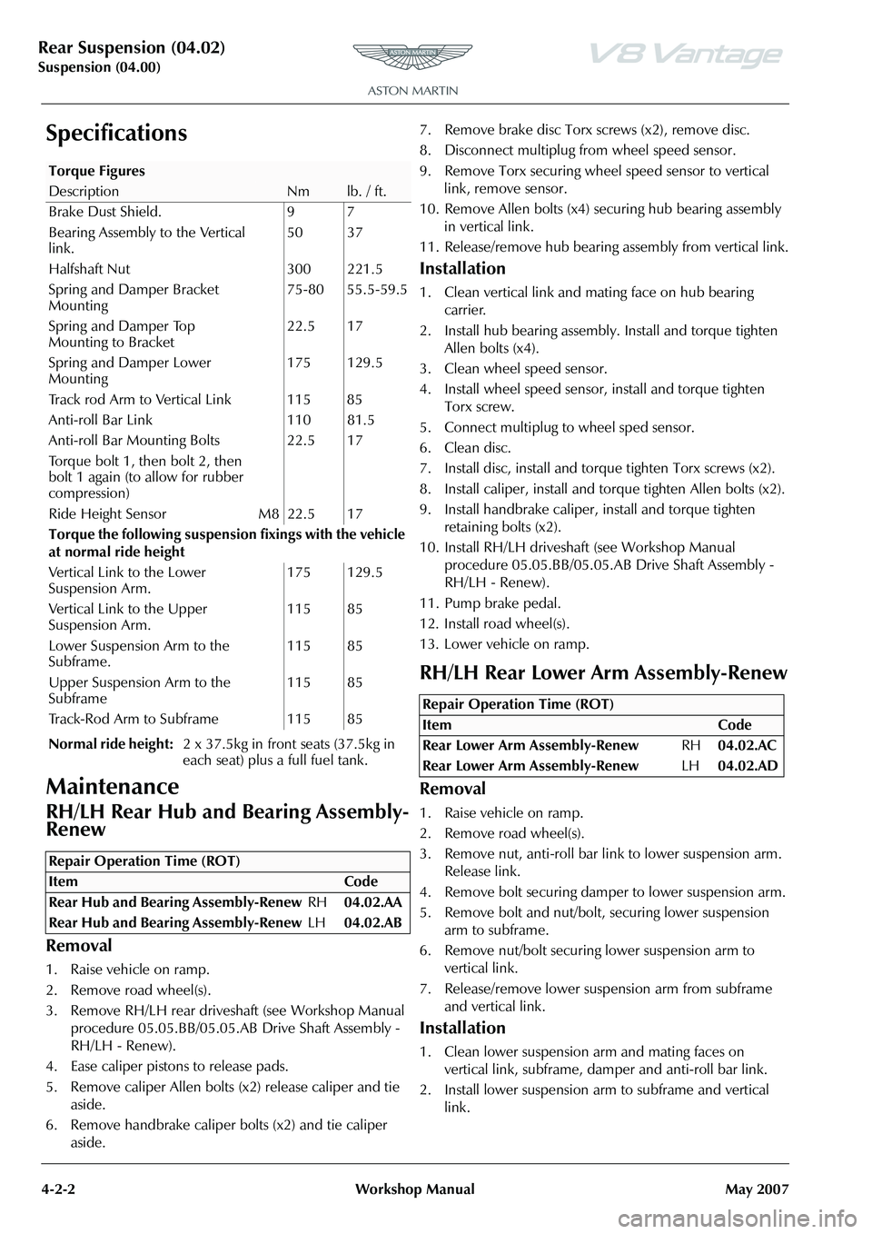
1. Raise vehicle on ramp.
2. Remove road wheel(s).
3. Remove RH/LH rear drivesha ft (see Workshop Manual
procedure 05.05.BB/05.05.AB Drive Shaft Assembly -
RH/LH - Renew).
4. Ease caliper pistons to release pads.
5. Remove caliper Allen bolts (x2) release caliper and tie aside.
6. Remove handbrake caliper bolts (x2) and tie caliper aside. 7. Remove brake disc Torx screws (x2), remove disc.
8. Disconnect multiplug fr
om wheel speed sensor.
9. Remove Torx securing wheel speed sensor to vertical link, remove sensor.
10. Remove Allen bolts (x4) se curing hub bearing assembly
in vertical link.
11. Release/remove hub bearing a ssembly from vertical link.
Installation
1. Clean vertical link and mating face on hub bearing
carrier.
2. Install hub bearing assembly. Install and torque tighten Allen bolts (x4).
3. Clean wheel speed sensor.
4. Install wheel speed sensor, install and torque tighten Torx screw.
5. Connect multiplug to wheel sped sensor.
6. Clean disc.
7. Install disc, install and torq ue tighten Torx screws (x2).
8. Install caliper, install and torque tighten Allen bolts (x2).
9. Install handbrake caliper, install and torque tighten
retaining bolts (x2).
10. Install RH/LH driveshaft (see Workshop Manual
procedure 05.05.BB/05.05.AB Drive Shaft Assembly -
RH/LH - Renew).
11. Pump brake pedal.
12. Install road wheel(s).
13. Lower vehicle on ramp.
RH/LH Rear Lower Arm Assembly-Renew
Removal
1. Raise vehicle on ramp.
2. Remove road wheel(s).
3. Remove nut, anti-roll bar li nk to lower suspension arm.
Release link.
4. Remove bolt securing damper to lower suspension arm.
5. Remove bolt and nut/bolt, securing lower suspension arm to subframe.
6. Remove nut/bolt securing lower suspension arm to
vertical link.
7. Release/remove lower suspension arm from subframe and vertical link.
Installation
1. Clean lower suspension arm and mating faces on vertical link, subframe, damper and anti-roll bar link.
2. Install lower suspension ar m to subframe and vertical
link.
Torque Figures
DescriptionNmlb. / ft.
Brake Dust Shield. 9 7
Bearing Assembly to the Vertical
link. 50 37
Halfshaft Nut 300 221.5
Spring and Damper Bracket
Mounting 75-80 55.5-59.5
Spring and Damper Top
Mounting to Bracket 22.5 17
Spring and Damper Lower
Mounting 175 129.5
Track rod Arm to Vertical Link 115 85
Anti-roll Bar Link 110 81.5
Anti-roll Bar Mounting Bolts
Torque bolt 1, then bolt 2, then
bolt 1 again (to allow for rubber
compression) 22.5 17
Ride Height Sensor M8 22.5 17
Torque the following suspensi on fixings with the vehicle
at normal ride height
Vertical Link to the Lower
Suspension Arm. 175 129.5
Vertical Link to the Upper
Suspension Arm. 115 85
Lower Suspension Arm to the
Subframe. 115 85
Upper Suspension Arm to the
Subframe 115 85
Track-Rod Arm to Subframe 115 85
Normal ride height: 2 x 37.5kg in front seats (37.5kg in
each seat) plus a full fuel tank.
Repair Operation Time (ROT)
Repair Operation Time (ROT)
ItemCode
Rear Lower Arm Assembly-Renew RH04.02.AC
Rear Lower Arm Assembly-Renew LH04.02.AD
Page 441 of 947
Shock Absorber System (04.03)
Suspension (04.00)
May 2007 Workshop Manual 4-3-1
Suspension (04.00)
Shock Absorber System (04.03)
Description
Movement of each road spring is independently damped by
a telescopic, hydraulically-controlled shock absorber. Each
shock absorber is installed coax ially within the road spring.
Front spring and damper assemblies are located between
the upper suspension arm and attach to the lower
suspension arm and the body structure.
Rear spring and damper assemblies attach to the lower
suspension arm and the rear subframe, via a mounting
bracket, laying to the rear of the upper suspension arm.
Specifications
Maintenance
Front Spring and Damper Assembly-Pair-
Renew
Removal
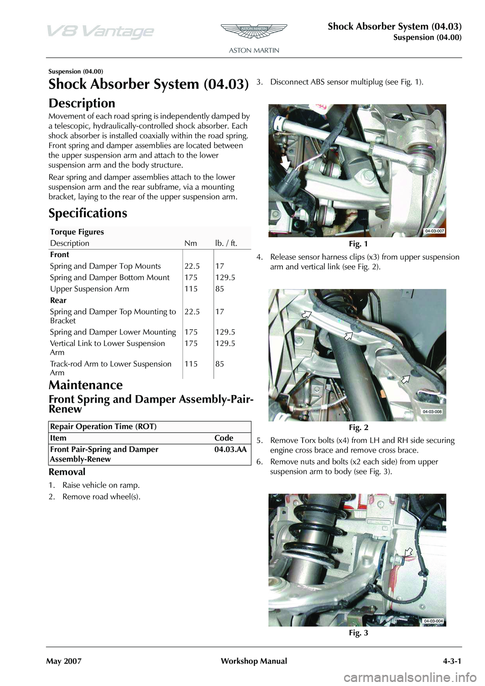
1. Raise vehicle on ramp.
2. Remove road wheel(s). 3. Disconnect ABS sensor
multiplug (see Fig. 1).
4. Release sensor harness clips (x3) from upper suspension arm and vertical li nk (see Fig. 2).
5. Remove Torx bolts (x4) fr om LH and RH side securing
engine cross brace and remove cross brace.
6. Remove nuts and bolts (x2 each side) from upper suspension arm to body (see Fig. 3).
Torque Figures
DescriptionNmlb. / ft.
Front
Spring and Damper Top Mounts 22.5 17
Spring and Damper Bottom Mount 175 129.5
Upper Suspension Arm 115 85
Rear
Spring and Damper Top Mounting to
Bracket 22.5 17
Spring and Damper Lower Mounting 175 129.5
Vertical Link to Lower Suspension
Arm 175 129.5
Track-rod Arm to Lower Suspension
Arm 115 85
Repair Operation Time (ROT)
Fig. 1
Fig. 2
Fig. 3
Page 453 of 947
Road Wheels and Tyres (04.04)
Suspension (04.00)
May 2007 Workshop Manual 4-4-3
Maintenance
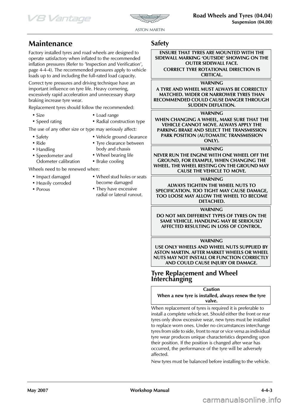
Factory installed tyres and road wheels are designed to
operate satisfactory when inflated to the recommended
inflation pressures (Refer to ’Inspection and Verification’,
page 4-4-4). The recommended pressures apply to vehicle
loads up to and including the full-rated load capacity.
Correct tyre pressures and driving technique have an
important influence on tyre life. Heavy cornering,
excessively rapid acceleration and unnecessary sharp
braking increase tyre wear.
Replacement tyres should follow the recommended:
The use of any other size or type may seriously affect:
Wheels need to be renewed when:
Safety
Tyre Replacement and Wheel
Interchanging
When replacement of tyres is required it is preferable to
install a complete vehicle set. S hould either the front or rear
tyres only show excessive wear, new tyres must be installed
to replace worn ones. Under no circumstances interchange
tyres from side to side, front to re ar or vice versa as individual
tyre wear produces unique characteristics depending upon
their position. If the position is changed after wear has
occurred, the performance of the tyre will be adversely
affected.
New tyres must be balanced before installing to the vehicle.
•Size
•Speed rating
•Load range
• Radial construction type
•Safety
•Ride
•Handling
• Speedometer and Odometer calibration • Vehicle ground clearance
• Tyre clearance between
body and chassis
• Wheel bearing life
• Brake cooling
• Impact damaged
• Heavily corroded
• Porous • Wheel stud holes or seats
become damaged
• They have excessive radial or lateral runout.
ENSURE THAT TYRES ARE MOUNTED WITH THE
SIDEWALL MARKING ‘OUTSIDE’ SHOWING ON THE
OUTER SIDEWALL FACE.
CORRECT TYRE ROTATIONAL DIRECTION IS CRITICAL.
WA R N I N G
A TYRE AND WHEEL MUST ALWAYS BE CORRECTLY MATCHED. WIDER OR NARROWER TYRES THAN
RECOMMENDED COULD CAUSE DANGER THROUGH
SUDDEN DEFLATION.
WA R N I N G
WHEN CHANGING A WHEEL, MAKE SURE THAT THE VEHICLE CANNOT MOVE. ALWAYS APPLY THE
PARKING BRAKE AND SELE CT THE TRANSMISSION
PARK POSITION (AUTOMATIC TRANSMISSION ONLY).
WA R N I N G
NEVER RUN THE ENGINE WITH ONE WHEEL OFF THE GROUND, FOR EXAMPLE, WHEN CHANGING THE
WHEEL. THE WHEEL RESTING ON THE GROUND MAY CAUSE THE VEHICLE TO MOVE.
WA R N I N G
ALWAYS TIGHTEN THE WHEEL NUTS TO
SPECIFICATION. TOO TIGHT MAY CAUSE DAMAGE,
TOO LOOSE MAY ALLOW TH E WHEEL TO BECOME
DETACHED.
WAR NI NG
DO NOT MIX DIFFERENT TY PES OF TYRES ON THE
SAME VEHICLE. HANDLING MAY BE SERIOUSLY AFFECTED RESULTING IN LOSS OF CONTROL.
WAR NI NG
USE ONLY WHEELS AND WHEEL NUTS SUPPLIED BY
ASTON MARTIN. AFTER MARKET WHEELS OR WHEEL
NUTS MAY NOT INSTALL OR FUNCTION CORRECTLY
AND COULD CAUSE INJURY OR DAMAGE.
Caution
When a new tyre is installe d, always renew the tyre
valve.
Page 457 of 947
Road Wheels and Tyres (04.04)
Suspension (04.00)
May 2007 Workshop Manual 4-4-7
Repairs
In view of the high performance capability of the vehicle,
damaged tyres should be renewed and not repaired.
Care of Alloy Road Wheels
Aluminium alloy road wheels are covered with a protective
coating. To prevent corrosion it is essential that this coating
is not damaged. When removing or installing tyres only
equipment utilizing spigot or stud hole clamping must be
used. The equipment must not have any moving parts which
contact the road wheel, and ty re levers must not be used.
To clean road wheels use warm soapy water; stubborn stains
can be removed using a soft brush or by using a proprietary
alloy road wheel cleaner.
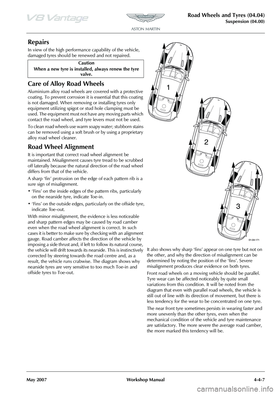
Road Wheel Alignment
It is important that correct road wheel alignment be
maintained. Misalignment causes tyre tread to be scrubbed
off laterally because the natural direction of the road wheel
differs from that of the vehicle.
A sharp ‘fin’ protrusion on the edge of each pattern rib is a
sure sign of misalignment.
• ‘Fins’ on the inside edges of the pattern ribs, particularly on the nearside tyre, indicate Toe-in.
• ‘Fins’ on the outside edges, particularly on the offside tyre, indicate Toe-out.
With minor misalignment, the ev idence is less noticeable
and sharp pattern edges may be caused by road camber
even when the road wheel alignment is correct. In such
c a s e s i t i s b e t t e r t o m a k e s u r e b y c h e c k i n g w i t h a n a l i g n m e n t
gauge. Road camber affects the direction of the vehicle by
imposing a side thrus t and , if le ft to follow its natural cou rs e,
the vehicle will drift towards its nearside. This is instinctively
corrected by steering towards the road centre and, as a
result, the vehicle runs crab wise. The diagram shows why
nearside tyres are very sensitive to too much Toe-in and
offside tyres to Toe-out. It also shows why sharp ‘fins’ appear on one tyre but not on
the other, and why the direction of misalignment can be
determined by noting the position of the ‘fins’. Severe
misalignment produces clea
r evidence on both tyres.
Front road wheels on a moving vehicle should be parallel.
Tyre wear can be affected noticeably by quite small
variations from this condition. It will be noted from the
diagram that even with parallel road wheels, the vehicle is
still out of line with its dire ction of movement, but there is
less tendency for the wear to be concentrated on one tyre.
The near front tyre sometimes persists in wearing faster and
more unevenly than the other tyres, even when the
mechanical condition of the vehicle and tyre maintenance
are satisfactory. The more severe the average road camber,
the more marked this tendency will be.
Caution
When a new tyre is installe d, always renew the tyre
valve.
Page 463 of 947
May 2007 Workshop Manual 5-1-1
Driveline (05.00)
Contents
Driveshaft (05.01) .................................................. 5-1-2Description ............................................................. 1-2
Specifications.......................................................... 1-2
Maintenance ........................................................... 1-2 Propeller Shaft-Renew ........................................... 1-2
Propshaft Cam Sensor-Sportshift-Renew
-Sportshift Only...................................................... 1-2
Torque Tube-Renew .............................................. 1-3
Torque Tube & Prop Shaft Assembly-
Renew-Manual Vehicles Only ................................ 1-4
Torque Tube & Prop Shaft Assembly-
Renew-Sportshift Vehicles Only ............................. 1-4
Torque Tube-Remove for Access/Refit .................... 1-5
RH/LH Drive Shaft Assembly-Renew ...................... 1-7
Halfshafts (05.05) .................................................. 5-2-1 Specifications.......................................................... 2-1
Page 464 of 947
Driveshaft (05.01)
Driveline (05.00)5-1-2 Workshop Manual May 2007
Driveline (05.00)
Driveshaft (05.01)
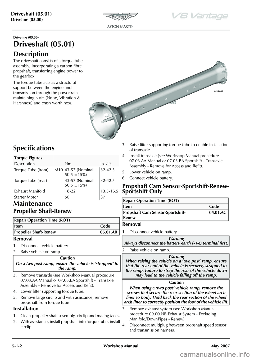
Description
The driveshaft consists of a torque tube
assembly, incorporating a carbon fibre
propshaft, transferring engine power to
the gearbox.
The torque tube acts as a structural
support between the engine and
transmission through the powertrain
maintaining NVH (Noise, Vibration &
Harshness) and crash worthiness.
Specifications
Maintenance
Propeller Shaft-Renew
Removal
1. Disconnect vehicle battery.
2. Raise vehicle on ramp.
3. Remove transaxle (see Workshop Manual procedure 07.03.AA Manual or 07.03.BA Sportshift - Transaxle
Assembly - Remove for Access and Refit).
4. Lower lifter supporting torque tube.
5. Remove large circlip and with assistance, remove propshaft from torque tube
Installation
1. Clean propeller shaft assembly, circlip and mating faces.
2. With assistance, install propshaft into torque tube, install circlip. 3. Raise lifter supporting torque tube to enable installation
of transaxle.
4. Install transaxle (see Workshop Manual procedure 07.03.AA Manual or 07.03.BA Sportshift - Transaxle
Assembly - Remove for Access and Refit).
5. Lower vehicle on ramp.
6. Connect vehicle battery.
Propshaft Cam Sensor-Sportshift-Renew-
Sportshift Only
Removal
1. Disconnect vehicle battery.
2. Raise vehicle on ramp.
3. Remove exhaust system (see Workshop Manual procedure 09.00.NB Exhaust System - Excluding
Manifold/DownPipes - Renew).
4. Disconnect multiplug between propshaft speed sensor and transmission harness.
Torque Figures
DescriptionNm.lb. / ft.
Torque Tube (front) M10 43-57 (Nominal 50.5 ±15%)32-42.5
Torque Tube (rear) 43-57 (Nominal 50.5 ±15%)32-42.5
Exhaust Manifold 18-22 13.5-16.5
Starter Motor 50 37
Repair Operation Time (ROT)
Repair Operation Time (ROT)
ItemCode
Propshaft Cam Sensor-Sportshift-
Renew 05.01.AC
Warning
Always disconnect the battery earth (- ve) terminal first.
Warning
When raising the vehicle on a ‘two post’ ramp, ensure
that the rear end of the vehi cle is securely strapped to
the ramp. Failure to strap th e rear of the vehicle down
may lead to the vehicl e falling off the ramp.
Caution
When using a ‘two post’ vehicle ramp, remove the
screws that secure the rear section of the wheel arch
liner to body. Hold back the rear section of the wheel
arch liner to correctly position the foot of the vehicle lift.
Page 473 of 947
Version 6, March 2010 Workshop Manual 6-3-1
Brake System (06.00)
Contents
Front Disc Brake (06.03)........................................ 6-3-2Description ............................................................. 3-2
Specifications.......................................................... 3-2
Maintenance ........................................................... 3-3Front Brake Disc Set - Renew ................................. 3-3
Front Caliper-Renew .............................................. 3-4
Front Pad Kit - Renew ............................................ 3-5
Front Brake Hose Assembly - Renew ...................... 3-5
Rear Disc Brakes (06.04) ....................................... 6-4-1 Description ............................................................. 4-1
Specifications.......................................................... 4-1
Maintenance ........................................................... 4-2Rear Brake Disc Set-Renew .................................... 4-2
RH/LH Rear Caliper-Renew ................................... 4-2
Rear Pad Kit-Renew ............................................... 4-3
Rear Brake Hose Assembly-Renew ......................... 4-4
Hand Brake (06.05) ................ ............................... 6-5-1
Description ............................................................. 5-1
Specifications.......................................................... 5-1
Maintenance ........................................................... 5-2 RH/LH Handbrake Caliper-Re new ......................... 5-2
Handbrake Lever Assembly-Renew ........................ 5-2
Handbrake Pad Set-Renew .................................... 5-2
Handbrake Cable Assembly-Adjust......................... 5-3
Handbrake Cable Assembly-Vehicle Set-Renew ..... 5-3
Brake Actuation System (06.06)............................. 6-6-1 Description ............................................................. 6-1
Tandem Master Cylinder ........................................ 6-1
Specifications.......................................................... 6-1
Maintenance ........................................................... 6-2Pedal Box Assembly - Renew ................................. 6-2
Installation ............................................................. 6-2
RHD-Brake Master Cylinder Assembly-Renew........ 6-2
LHD-Brake Master Cylinder Assembly-Renew ........ 6-3
Clutch Master Cylinder Assembly-Renew ............... 6-3
RH/LH Front Caliper Hose Assembly-Renew .......... 6-4
RH/LH Rear Brake Caliper Tube Assembly-Renew . 6-5
Brake Master Cylinder to Modulator Secondary
Tube Assembly-Renew ........................................... 6-6
Brake Master Cylinder to Modulator Primary
Tube Assembly-Renew ........................................... 6-7
Rear Wheel Brake Front to Rear Tube Assembly
-Renew .................................................................. 6-8
RH Front Caliper to Modulator Tube Assembly
-Renew .................................................................. 6-9
Rear Wheel Brake Tube Assembly-Renew ............ 6-10
Dynamic Stability Control Module-Renew............ 6-11
Power Brake System (06.07) .................................. 6-7-1 Brake Booster ......................................................... 7-1
Emergency Brake Assist .......................................... 7-1
Specifications.......................................................... 7-2
Maintenance ........................................................... 7-2Brake Booster-RHD-Renew.................................... 7-2
Brake Booster-LHD-Renew .................................... 7-2 Brake Fluid Reservoir-Renew ................................. 7-3
Brake Bleeding - AMDS ......................................... 7-3
Brake Master Cylinder and Vacuum Booster
-Renew .................................................................. 7-4
Brake Master Cylinder-Renew ................................ 7-5
Anti-lock Braking System (ABS) (06.09)................. 6-9-1 Dynamic Stability Control ...................................... 9-1Concept ................................................................ 9-1
System Overview ................................................... 9-2
Operation Summary .............................................. 9-2
Traction Control ..................................................... 9-2 Functional Description ........................................... 9-2
Engine Intervention ................................................ 9-3
Brake Intervention ................................................. 9-3
ABS / DSC Circuit .................................................. 9-3
Specifications ......................................................... 9-3 Maintenance ......................................................... 9-4
ABS Modulator - Remove and Install ...................... 9-4
Page 475 of 947
Front Disc Brake (06.03)
Brake Systems (06.00)
Version 6, March 2010 Workshop Manual 6-3-3
Maintenance
Front Brake Disc Set - Renew
Removal
1. Raise the vehicle and make it safe.
2. Remove the road wheels.
3. Remove the pad wear sensors.
4. Remove the dust caps from the bleed nipples.
5. Install a bleed bottle.
6. Loosen the bleed nipples.
7. Push the pistons into calipers and tighten the bleed nipples.
8. Remove the bleed bottle.
9. Install the dust caps on the bleed screws.
10. Remove the brake pad retaining pins and anti-rattle springs.
11. Remove the two caliper attachment bolts from each caliper.
12. Use a cable tie to hold each caliper away.
13. Remove the two disc attachment screws and the two discs.
Installation
1. Clean the two hubs. 2. Install the two discs.
3. Install and torque two attachment screws into each disc.
4. Put each caliper in position and attach it with two new
bolts.
5. Torque the caliper attachment bolts.
6. Clean the calipers, pins, shims and springs.
7. Apply anti-seize compound to the pads, pins and shims.
8. Install the pads and shims into the caliper.
9. Install the pad retaining pins and springs into the calipers.
10. Install the pad wear sensors.
11. Operate the brake pedal four times.
12. Fill the brake fluid reservoir to the correct level.
13. Install the road wheels.
14. Lower the vehicle.
Repair Operation Time (ROT)
WAR NI NG
ALWAYS INSTALL NEW BOLTS WHEN YOU INSTALL THE BRAKE CALIPER. IF YOU DO NOT THE BOLTS
CAN BREAK AND CAUSE FAILURE OF THE BRAKE.
When you install new brake pads, install a new brake pad wear sensor.
WA R N I N G
BEFORE YOU DRIVE THE VEHICLE, OPERATE THE
FOOT BRAKE PEDAL 2 OR 3 TIMES TO MAKE SURE
THAT THE FOOT BRAKE OPERATES CORRECTLY. YOU MUST OPERATE BRAKE CALIPER PISTONS TO CLOSE THE SPACE BETWEEN THE BRAKE PADS AND THE
DISC.
Page 480 of 947
Rear Disc Brakes (06.04)
Brake system (06.00)6-4-2 Workshop Manual May 2007
Maintenance
Rear Brake Disc Set-Renew
Removal
1. Raise vehicle on ramp.
2. Remove road wheel/s
3. Remove pad wear sensors.
4. Remove bleed nipple dust caps.
5. Fit bleed bottle.
6. Loosen bleed nipples, push pistons into Calipers, tighten bleed nipples.
7. Remove bleed bottle.
8. Fit bleed screw dust caps.
9. Remove brake pad retaining pins and anti-rattle springs.
10. Remove Caliper bolts (x4) and tie Caliper aside.
11. Remove handbrake Caliper bolts (x4) and tie Calipers aside.
12. Remove retaining screws (x4) and discs.
Installation
1. Clean hubs.
2. Install discs and retaining screws.
3. Install Calipers and retaining bolts.
4. Install handbrake Ca lipers (bolts x4).
5. Clean components (Caliper s, pins, shims, springs)6. Apply anti-seize compound to pads, pins and shims.
7. Install pads and shims to Caliper.
8. Install retaining pad pins
and springs to Calipers.
9. Install pad wear sensors.
10. Pump brake pedal.
11. Top-up brake fluid.
12. Install road wheel/s
13. Lower vehicle on ramp.
RH/LH Rear Caliper-Renew
Removal
1. Raise vehicle on ramp.
2. Remove road wheel/s
3. Remove pad wear sensor.
4. Ease Caliper pistons to release pads.
5. Remove brake pad retaining pins and anti-rattle spring.
6. Remove pads and shims from Caliper.
7. Remove brake hose (cap and plug open orifices).
8. Remove Caliper bolts (x2) and Caliper.
Repair Operation Time (ROT)
When installing new brake pads, install a new brake pad wear sensor.
WAR NI NG
BEFORE MOVING OFF, PUMP THE FOOT BRAKE 2 OR
3 TIMES TO ENSURE THE FOOT BRAKE WORKS
CORRECTLY. BRAKE CALIPER PISTONS MAY REQUIRE TRAVEL TO CONTACT THE BRAKE PADS AND DISC.
Repair Operation Time (ROT)
ItemCode
Rear Caliper-Renew RH06.04.AB
Rear Caliper-Renew LH06.04.AC
WAR NI NG
AVOID SKIN / EYE CONTACT OR INGESTION OF
BRAKE FLUID. IF SKIN OR EYES ARE SPLASHED WITH BRAKE FLUID, RINSE THE AFFECTED AREA
IMMEDIATELY WITH PLENTY OF WATER AND OBTAIN
MEDICAL ATTENTION. IF BR AKE FLUID IS INGESTED,
OBTAIN IMMEDIATE MEDICAL ATTENTION.
WAR NI NG
BRAKE FLUID IS HYGROSCOPIC. IF KEPT IN OPENED CONTAINERS IT WILL ABSORB WATER VAPOUR. USE ONLY BRAKE FLUID FROM FRESHLY OPENED
CONTAINER.
Caution
Brake fluid must not be allowed to contact the vehicle
paint work. Remove spilt brake fluid from the paint work
by rinsing away with running water.
Place an absorbent cloth around the brake fluid reservoir filler neck to absorb any possible brake fluid spillage.