transmission ASTON MARTIN V8 VANTAGE 2010 Manual PDF
[x] Cancel search | Manufacturer: ASTON MARTIN, Model Year: 2010, Model line: V8 VANTAGE, Model: ASTON MARTIN V8 VANTAGE 2010Pages: 947, PDF Size: 43.21 MB
Page 793 of 947

Squeaks and Rattles Repair Manual
July 2010 Page 9 of 21
Satellite Navigation (Sat-Nav) Lid Rattles
Sat-Nav Tapping Noise
SRO:10.07.CH
Safe VINs: DB9 - A12390, V8 Vantage - C13317, DBS - E01313
Repair
CAUTION:
BE CAREFUL WHEN YOU RELEASE THE INSTRUMENT PANEL VENEER BEZEL. THE SURFACE
FINISH CAN BE EASILY DAMAGED.
1. Release the clips that attach the centre-sta ck instrument panel (refer to Figure 1).
Figure 1
2. Disconnect the electrical connectors from each of the fo ur transmission control switches (refer to Figure 2).
Figure 2
3. Disconnect the electrical connector from the igni tion start/stop switch (refer to Figure 3).
Page 795 of 947

Squeaks and Rattles Repair Manual
July 2010 Page 11 of 21
Figure 6
10. Connect the electrical connector to ignition start/stop switch (refer to Figure 7).
Figure 7
11. Connect the electrical connectors to each of the four transmission control switches (refer to Figure 8).
Figure 8
12. Make sure that the heater vents are correctly aligned.
Page 797 of 947

Squeaks and Rattles Repair Manual
July 2010 Page 13 of 21
Sat-Nav Chatter
SRO: 19.07.CG
Safe VINs: DBS - E01840, DB9 - A12676, V8 Vantage - C13743
Repair:
Pre safe VIN
CAUTION:
BE CAREFUL WHEN YOU RELEASE THE INSTRUMENT PANEL VENEER BEZEL. THE SURFACE FINISH CAN BE EASILY DAMAGED.
1. Release the four clips that attach the centre-s tack instrument panel (refer to Figure 1).
Figure 1
2. Disconnect the electrical connectors from each of the fo ur transmission control switches (refer to Figure 2).
Figure 2
3. Disconnect the electrical connector from the igni tion start/stop switch (refer to Figure 3).
Page 799 of 947

Squeaks and Rattles Repair Manual
July 2010 Page 15 of 21
Figure 6
9. Install the sat-nav top panel.
10. Put the instrument panel into po sition (refer to Figure 7).
Figure 7
11. Connect the electrical connector to ignition start/stop switch (refer to Figure 8).
Figure 8
12. Connect the electrical connectors to each of the four transmission control switches (refer to Figure 9).
Page 801 of 947

Squeaks and Rattles Repair Manual
July 2010 Page 17 of 21
Sat-Nav Rattle (Loose in the aperture)
SRO: 19.07.CJ
Safe VINs: DBS - E01610, DB9 - A12546, V8 Vantage - C13503, V12 Vantage - S00185
Repair
CAUTION:
BE CAREFUL WHEN YOU RELEASE THE INSTRUMENT PANEL VENEER BEZEL. THE SURFACE FINISH CAN BE EASILY DAMAGED.
1. Release the four clips that attach the centre-s tack instrument panel (refer to Figure 1).
Figure 1
2. Disconnect the electrical connectors from each of the fo ur transmission control switches (refer to Figure 2).
Figure 2
3. Disconnect the electrical connector from the igni tion start/stop switch (refer to Figure 3).
Page 804 of 947

Squeaks and Rattles Repair Manual
Page 20 of 21 Issue 3
Figure 9
12. Connect the electrical connectors to each of the four transmission control switches (refer to Figure 10).
Figure 10
13. Make sure that the heater vents are correctly aligned.
14. Push the centre-stack instrument panel until it engages with the four retaining clips.
Page 846 of 947

Contents
Item No. of Pages
1. EOBD Monitors Summary 43
Dated 1st May 2009
2. 09MY V8 Vantage EOBD Documentation
a. D ata Tables 13
b. Function Tables 1
c. Notes 1
d. ASM Transmission Data Tables 6
3. V12 Family EOBD Documentation
V12 Vantage, 09MY DBS & 09MY DB9 EOBD Documentation
e. Data Tables 16
f. Function Tables 2
g. Notes 2
h. 09MY DB9 & DBS Automatic Transmission Summary 4
Note: The V12 EOBD engine family is certified as a single submission.
The calibration content and therefore th e data is identical for each model
with the V12 engine; V12 Vantage, DBS and DB9.
The Automatic Transmission summary is included but does not apply to
the V12 Vantage.
Page 848 of 947

AML EOBD System Operation Summary
Rory O’Curry Aston Martin Lagonda CONFIDENTIAL 1 May 2009
[email protected] AML EOBD Monitors 07 ROC.doc Page 2 of 43
AML EOBD System Operation
Summary for Gasoline Engines.
Contents
Introduction ........................................................................................................................................................................................3
Catalyst Efficiency Monitor ...............................................................................................................................................................4
Misfire Monitor..................................................................................................................................................................................6
Fuel System Monitor ..........................................................................................................................................................................9
HO2S Monitor............................................................................................................................... ...................................................10
Differential Pressure Feedback EGR System Monitor.....................................................................................................................13
Electronic Throttle Monitor............................................................................................................................... ...............................16
Dual MAF Diagnostic............................................................................................................................... .......................................18
SAIR Monitor............................................................................................................................... ....................................................22
VCT Monitor............................................................................................................................... .....................................................25
Comprehensive Component Monitor - Engine............................................................................................................................... ..27
Comprehensive Component Monitor - Manual Transmission..........................................................................................................30
Comprehensive Component Monitor - Automatic Transmission .....................................................................................................31
6HP26 Automatic Transmission............................................................................................................................... ........................34
Auto Shift Manual (ASM) Transmission............................................................................................................................... ...........34
Inspection Maintenance Readiness Code............................................................................................................................... ..........35
Tamper Protection............................................................................................................................... .............................................35
Serial Data Link Connector............................................................................................................................... ...............................35
Serial Data Link Communication Protocol............................................................................................................................... ........35
Serial Data Link MIL Illumination............................................................................................................................... ....................36
Glossary of Terms............................................................................................................................... .............................................37
MIL Code List............................................................................................................................... ...................................................39
MIL Symbol............................................................................................................................... ......................................................43
Page 849 of 947

AML EOBD System Operation Summary
Rory O’Curry Aston Martin Lagonda CONFIDENTIAL 1 May 2009
[email protected] AML EOBD Monitors 07 ROC.doc Page 3 of 43
Introduction
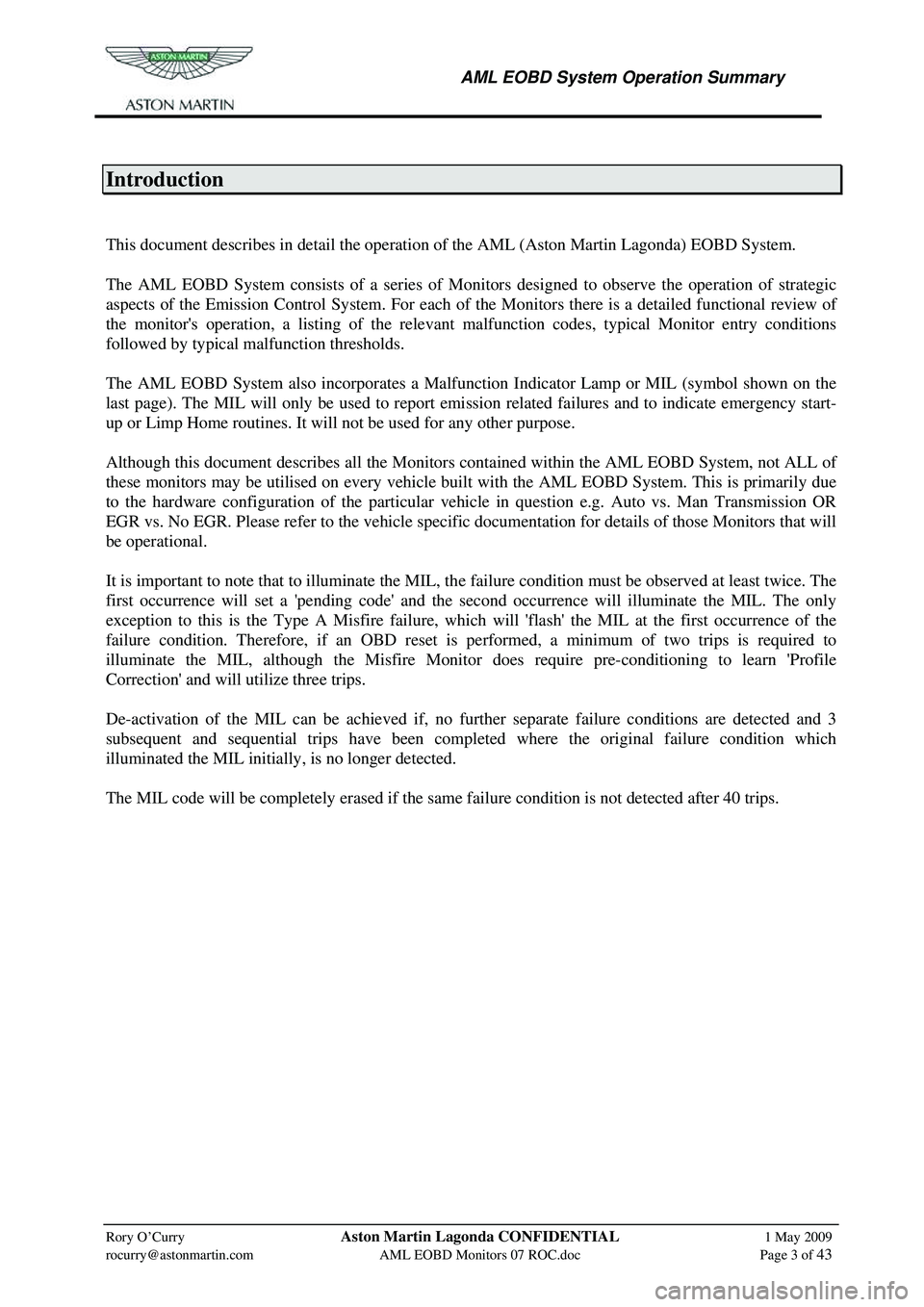
This document describes in detail the operation of the AML (Aston Martin Lagonda) EOBD System.
The AML EOBD System consists of a series of Mon itors designed to observe the operation of strategic
aspects of the Emission Control System. For each of the Monitors there is a detailed functional review of
the monitor's operation, a listing of the relevant malfunction codes, typical Monitor entry conditions
followed by typical malfunction thresholds.
The AML EOBD System also incorporates a Malfunction Indicator Lamp or MIL (symbol shown on the
last page). The MIL will only be used to report emi ssion related failures and to indicate emergency start-
up or Limp Home routines. It will not be used for any other purpose.
Although this document describes all the Monitors cont ained within the AML EOBD System, not ALL of
these monitors may be utilised on every vehicle built w ith the AML EOBD System. This is primarily due
to the hardware configuration of the particular vehicle in question e.g. Auto vs. Man Transmission OR
EGR vs. No EGR. Please refer to the vehicle specific documentation for details of those Monitors that will
be operational.
It is important to note that to illuminate the MIL, th e failure condition must be observed at least twice. The
first occurrence will set a 'pending code' and the second occurrence will illuminate the MIL. The only
exception to this is the Type A Misfire failure, whic h will 'flash' the MIL at the first occurrence of the
failure condition. Therefore, if an OBD reset is performed, a minimum of two trips is required to
illuminate the MIL, although the Misfire Monitor does require pre-conditioning to learn 'Profile
Correction' and will utilize three trips.
De-activation of the MIL can be achieved if, no furt her separate failure conditions are detected and 3
subsequent and sequential trips have been comp leted where the original failure condition which
illuminated the MIL initially, is no longer detected.
The MIL code will be completely erased if the same failure condition is not detected after 40 trips.
Page 876 of 947

AML EOBD System Operation Summary
Rory O’Curry Aston Martin Lagonda CONFIDENTIAL 1 May 2009
[email protected] AML EOBD Monitors 07 ROC.doc Page 30 of 43
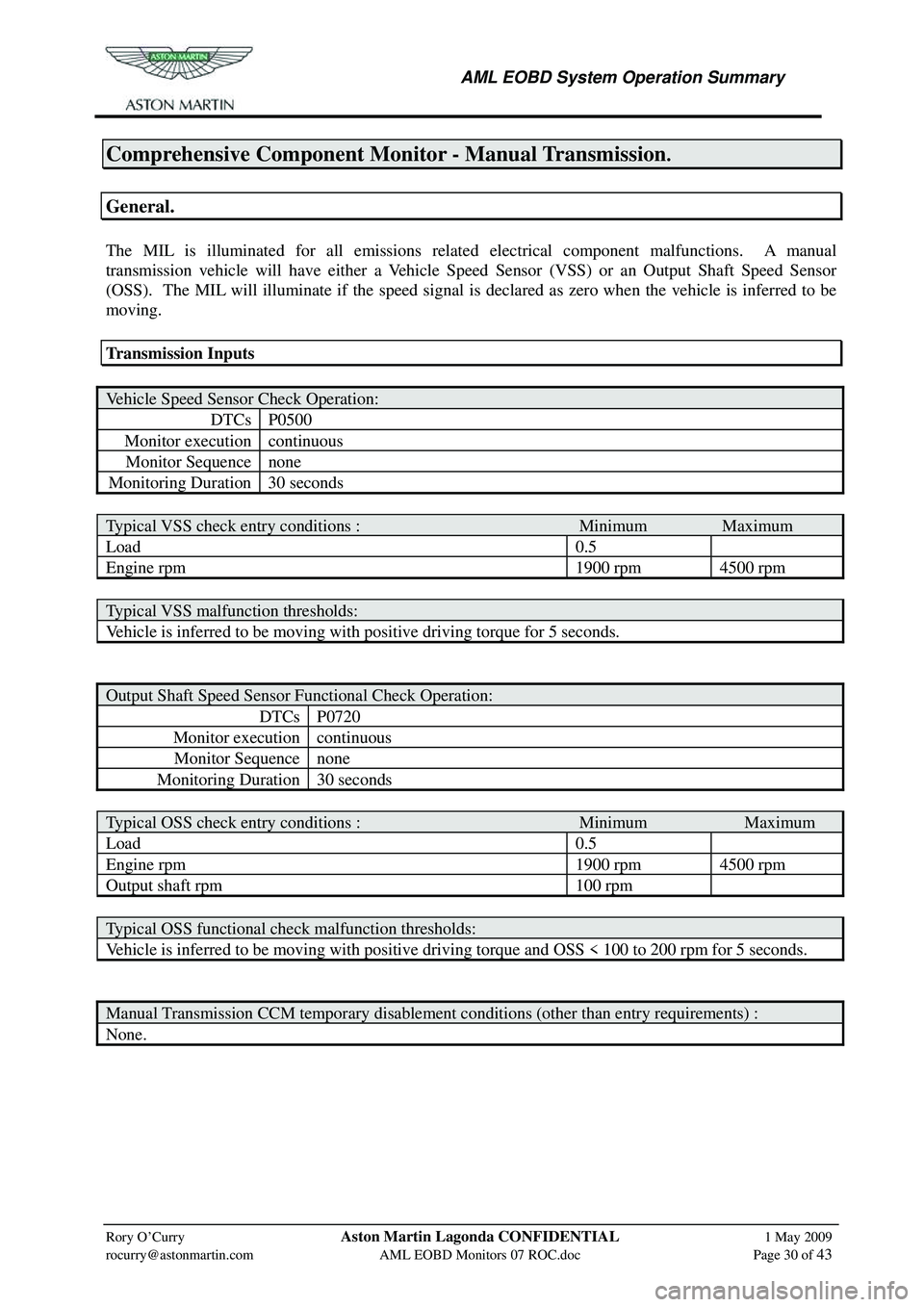
Comprehensive Component Monitor - Manual Transmission.
General.
The MIL is illuminated for all emissions relate d electrical component malfunctions. A manual
transmission vehicle will have either a Vehicle Speed Sensor (VSS) or an Output Shaft Speed Sensor
(OSS). The MIL will illuminate if the speed signal is declared as zero when the vehicle is inferred to be
moving.
Transmission Inputs
Vehicle Speed Sensor Check Operation:
DTCs P0500
Monitor execution continuous
Monitor Sequence none
Monitoring Duration 30 seconds
Typical VSS check entry conditions : Minimum Maximum
Load 0.5
Engine rpm 1900 rpm 4500 rpm
Typical VSS malfunction thresholds:
Vehicle is inferred to be moving with positive driving torque for 5 seconds.
Output Shaft Speed Sensor Functional Check Operation:
DTCs P0720
Monitor execution continuous
Monitor Sequence none
Monitoring Duration 30 seconds
Typical OSS check entry conditions : Minimum Maximum
Load 0.5
Engine rpm 1900 rpm 4500 rpm
Output shaft rpm 100 rpm
Typical OSS functional check malfunction thresholds:
Vehicle is inferred to be moving with positive driving torque and OSS < 100 to 200 rpm for 5 seconds.
Manual Transmission CCM temporary disablement conditions (other than entry requirements) :
None.