11-2 ASTON MARTIN V8 VANTAGE 2010 Workshop Manual
[x] Cancel search | Manufacturer: ASTON MARTIN, Model Year: 2010, Model line: V8 VANTAGE, Model: ASTON MARTIN V8 VANTAGE 2010Pages: 947, PDF Size: 43.21 MB
Page 3 of 947

Contents
Issue 5, January 2010 Workshop Manual 0-0-3
V8 Vantage Workshop Manual
Contents
IntroductionWelcome .............................................................. 0-0-6
Safety Precautions ................................................. 0-0-7
Lifting and Jacking ................................................. 0-0-9
Vehicle Recovery ................................................ 0-0-10
Vehicle Identification Number ............................ 0-0-11
Body System (01.00) Body Structure (01.01) .......................................... 1-1-4
Front End System (01.02) ...................................... 1-2-1
Body Closures (01.03) ........................................... 1-3-1
Interior Trim (01.05) ............................................. 1-4-1
Exterior Trim (01.08) ............................................. 1-8-1
Mirrors (01.09) ...................................................... 1-9-1
Seating (01.10).................................................... 1-10-1
Glass, Frame and Mechanism (01.11) .................. 1-11-1
Instrument Panel (IP) (01.12) . .............................. 1-12-1
Handles and Lock Mechanisms (01.14) ............... 1-14-1
Wipers and Washer System (01.16)..................... 1-16-1
Convertible Roof and Roof Opening
Subsystem (01.17)................ ...............................1-17-1
Bumpers (01.19) ................................................. 1-19-1
Restraining Devices (01.20) .... ............................. 1-20-1
Frame and Mounting (02.00) Subframes (02.03) ................................................. 2-1-2
Engine System (03.00) Engine Assembly....................................................3-0-3
Engine Structure (03.01)........................................ 3-1-1
Lubrication System (03.02).................................... 3-2-1
Cooling System (03.03) ......................................... 3-3-1
Fuel Charging System (03.04) ................................ 3-4-1
Accessory Drive System (03.05)............................. 3-5-1
Engine Cranking System (03. 06) ............................ 3-6-1
Valve Train (03.09) ............................................... 3-9-1
Engine Sealing (03.10)......................................... 3-10-1
Power Conversion (03.11)................................... 3-11-1
Evaporative Emissions (03.13) ............................. 3-11-1
Engine Management System (0 3.14).................... 3-14-1
Throttle Control (03.16) ...... ................................ 3-16-1
Foot Operated Control (03.18)............................ 3-18-1
Suspension (04.00) Road Wheel Alignment (04.00) ............................. 4-0-2
Front Suspension (04.01)....................................... 4-1-1
Rear Suspension (04.02)........................................ 4-2-1
Shock Absorber System (04.03) ............................. 4-3-1
Road Wheels and Tyres (04.04) ............................ 4-4-1
Driveline (05.00) Driveshaft (05.01) ................................................. 5-1-2
Halfshafts (05.05) .................................................. 5-2-1 Brake System (06.00)
Front Disc Brake (06.03) ....................................... 6-3-2
Rear Disc Brakes (06.04) ....................................... 6-4-1
Hand Brake (06.05) .............................................. 6-5-1
Brake Actuation System (06.06 ) ............................ 6-6-1
Power Brake System (06.07) ................................. 6-7-1
Anti-lock Braking System (06.09)........................... 6-9-1
Transmission (07.00) Transmission Cooling (07.02) ................................ 7-0-2
Manual Transmission (07.03) ................................ 7-3-1
Automatic Control System (07.05)......................... 7-5-1
Manual Control System (07.06) ............................. 7-6-1
Automatic Shifting Subsytem (07.11) .................. 7-11-1
Clutch (08.00) Clutch Controls (08.02) ......................................... 8-1-2
Exhaust (09.00) Exhaust Overview ................................................. 9-1-2
Silencer Assembly (09.01) ..................................... 9-1-3
Pipes and Supports (09.03) ................................... 9-2-1
Exhaust Protection (09.04) .................................... 9-3-1
Fuel (10.00) Fuel Tank and Lines (10.01) ................................ 10-1-2
Steering (11.00) Steering Gear (11.01) .......................................... 11-1-2
Power Steering (11.02)........................................ 11-2-1
Steering Column (11.04) ..................................... 11-4-1
Steering Column Switches (1 1.05) ....................... 11-5-1
Steering Wheel (11.06) ....................................... 11-6-1
Climate Control (12.00) Body Ventilation system (12.01) .......................... 12-1-2
Heater System (12.02) ........................................ 12-2-1
Air Conditioning (A/C) System (12.03) ................. 12-3-1
Information, Gauge and Warning (13.00) Instrument Cluster (13.01) .................................. 13-1-2
Power Supply (14.00) Battery System (14.01) ........................................ 14-1-2
Alternator and Regulator System (14.02) ............. 14-2-1
Vehicle Entertainment (15.00) Audio System (15.01)................................ ..........15-1-2
Antenna (15.02).................................................. 15-2-1
Vacuum Distribution (16.00) Body Vacuum System (16.01) ............................. 16-1-2
Lighting (17.00) Front Lights (17.01) ............................................. 17-1-2
Interior Lighting (17.02) ...................................... 17-2-1
Rear Lights (17.03) .............................................. 17-3-1
Lighting Mechanisms (17.04). .............................. 17-4-1
Page 14 of 947

1-1-2 Workshop Manual Issue 5, January 2010
RH/LH Seat Switchpack Assembly - Renew...........7-13
Lumbar Pump for the Front Seat (From 08MY)
- Remove and Install.............................................7-13
Lumbar Valve for the Front Seat (From 08MY)
- Remove and Install.............................................7-14
Lumbar Bladder for the Front Seat (From 08MY)
- Remove and Install.............................................7-14
Glass, Frame and Mechanism (01.11) .................. 1-8-1 Description .............................................................8-1 Frameless doors......................................................8-1
Specifications .........................................................8-1
Maintenance ...........................................................8-1 Glass Regulator - Renew .........................................8-1
RH/LH Door Glass - Renew ....................................8-2
Door Glass - Adjust/Reset .......................................8-3
Front Windshield - Renew ......................................8-3
Rear Windshield - Renew .......................................8-4
Quarter Window Glass - Renew .............................8-6
Passenger Window Lift Switch - Renew ..................8-6
Driver Window Lift Switch - Renew........................8-7
Instrument Panel (IP) (01.12)................................ 1-9-1 Specifications ..........................................................9-1
Maintenance ...........................................................9-1 Instrument Panel - Renew ......................................9-1
Airbag Panel and Door Assembly - Renew ..............9-6
Glovebox Assembly - Renew ..................................9-6
Instrument Centre Panel Asse mbly - Renew............9-7
Knee Protector - Renew .........................................9-7
Instrument Panel As sembly - Renew .......................9-7
Cluster Bezel Panel - Renew .................................9-10
Driver Panel Assembly - Renew ............................9-10
Instrument Panel Bezel A ssembly (With Sat. Nav.)
- Renew ...............................................................9-11
Instrument Panel Bezel Assembly
(Without Sat. Nav.) - Renew .................................9-11
Rear Console Panel Assembly - Renew .................9-12
Armrest Pad Assembly - Renew ............................9-13
Console Panel Assembly - Renew .........................9-13
RH/LH Rear Console Pa nel Assembly - Renew
(Roadster Only) ....................................................9-13
Centre Console Panel - Remove and Install
(Coupe Only) .......................................................9-15
Centre Console Panel - Remove and Install
(Roadster Only) ....................................................9-19
RH/LH Lower Quarter Panel Assembly - Renew
(Roadster Only) ....................................................9-29
Handles and Lock Mechanisms (01.14) .............. 1-10-1 Description ...........................................................10-1 Vehicle Key/Remote Transmitter...........................10-1
Central Locking System ........................................10-1
Remote Transmitter ..............................................10-1
Fuel Filler Assembly ..............................................10-1
Boot Emergency Release ....... ...............................10-1
Specifications ........................................................10-2
Maintenance .........................................................10-2 Ignition Cylinder Lock - Re new.............................10-2
RH/LH Front Door Latch As sembly - Renew .........10-2
Bonnet Latch Assembly - Renew...........................10-3
Hood Release Cable Assembly - Renew (Roadster Only) .................................................... 10-3
Bonnet Secondary Latch Asse
mbly - Renew ......... 10-4
Tailgate Latch and Cable Assembly - Renew ......... 10-4
Fuel Filler Actuator Assembly - Renew
(Roadster Only) .................................................... 10-4
Fuel Filler Release Cable - Renew (Roadster Only) 10-5
Fuel Flap Release Switch - Renew ........................ 10-6
RH/LH Tonneau Latch Motor - Renew
(Roadster Only) .................................................... 10-7
RH/LH Tonneau Latch - Renew (Roadster Only) ... 10-7
RH/LH Tonneau Cover Striker Assembly
- Renew (Roadster Only) ...................................... 10-8
Tailgate Latch Assembly-Renew (Roadster Only) ... 10-8
Wipers and Washer System (01.16) ....................1-11-1 Headlamp Washing .............................................. 11-1
Specifications ........................................................ 11-2
Maintenance ......................................................... 11-2 Windscreen Wiper Motor As sembly - Renew ....... 11-2
Wiper Linkage Assembly - Renew ........................ 11-2
Windshield Wash Tube - Renew .......................... 11-2
Windscreen Reservoir and Motor Assembly
- Remove and Install ............................................ 11-3
Low Level Water Sensor - Remove and Install ...... 11-4
Headlamp Wash Motor and Pump Assembly
- Renew ............................................................... 11-5
Headlamp Wash Tube Assembly - Renew ............ 11-5
Washer Fluid Reservoir - Renew........................... 11-6
Convertible Roof and Roof Opening Subsystem
(01.17)..................................................................1-12-1 System Description .............................................. 12-1
Maintenance ......................................................... 12-2 Hood Assembly-Renew ........................................ 12-2
Canopy Cover - Renew ........................................ 12-5
Header Latch Motor - Renew ............................... 12-9
Hydraulic Main Actuator Cy linder - Renew .......... 12-9
Hydraulic Tensrod Cylinder - Renew .................. 12-10
Hydraulic Tonneau Cylinder - Renew................. 12-11
Convertible Top ECU - Renew ........................... 12-13
Hydraulic Pump - Renew ................................... 12-13
Hydraulic Lock Valve - Renew............................ 12-16
RH/LH Front Cantrail Seal - Spare Part
- Renew ............................................................. 12-18
RH/LH Front Cantrail Seal Spare Part Kit
- Renew ............................................................. 12-18
RH/LH Middle Cantrail Seal Spare Part
- Renew ............................................................. 12-18
RH/LH Middle Cantrail Seal Spare Part Kit
- Renew ............................................................. 12-19
Rear Seal Spare Part Assembly Kit - Renew ......... 12-20
LH Fully Automatic Latching Kit - Renew............ 12-21
RH Fully Automatic Latching Kit - Renew ........... 12-22
Convertible Roof Hydraulic Pump
- Check Fluid Level ............................................ 12-23
Cantrail Cover Trim - Renew .............................. 12-25
B-Post Trim Cover - Renew ................................ 12-25
Tonneau Cover - Renew .................................... 12-27
LH Front Main Hydraulic Cylinder Pipe
- Renew ............................................................. 12-29
LH Rear Main Hydraulic Cylinder Pipe
Page 132 of 947

Wipers and Washer System (01.16)
Body System (01.00)1-11-2 Workshop Manual Issue 4,November, 2008
Specifications
Maintenance
Windscreen Wiper Motor Assembly -
Renew
Removal
1. Remove wiper linkage.
2. Remove arm from motor (nut x1).
3. Remove motor from plate (bolts x3).
Installation
1. Install motor to plate (bolts x3).
2. Ensure wiper motor is in the ‘PARK’ position.
3. Install arm from motor (nut x1), using special tool.
4. Install wiper linkage.
Wiper Linkage Assembly - Renew
Removal
1. Remove brake booster (see Workshop Manual procedure 06.07.DE/06.07.DG Master Cylinder and
Vacuum Booster - Brake - Renew).
2. Remove inlet manifold (see Workshop Manual procedure 03.01.BB/03.01.BF Gasket - Manifold
Assembly - Intake Upper - Renew).
3. Remove wiper arm drivers si de (see Workshop Manual
procedure 01.16.AD Arm Asse mbly - Wiper - Driver -
Renew).
4. Remove wiper arm passengers side (see Workshop Manual procedure 01.16.AE Arm Assembly - Wiper -
Passenger - Renew).
5. Unclip expansion tank hose for access. 6. Remove sound deadening (trim buttons x6).
7. Remove seal from spindle.
8. Remove nuts (x2) from heatshield to move aside.
9. Unclip wiper motor harness (x2) LHS.
10. Unclip windscreen heater harness RHS.
11. Disconnect motor multiplu
g and unclip harness (x2).
12. To prevent damage, protect A/C pipe with tape before
wiper linkage removal.
13. Remove plate securing scre ws (x10) (through plenum).
14. Remove plate securing bolts (x8) (under bonnet).
15. Remove wiper linkage.
Installation
1. Install wiper linkage.
2. Install plate securing bolts (x8) (under bonnet).
3. Install plate securing scre ws (x10) (through scuttle
panel).
4. Connect motor multiplug and clip harness (x2).
5. Clip harness LHS.
6. Clip harness RHS.
7. Refit heatshield and install nuts (x2).
8. Install seal to spindle.
9. Install sound deadening (re-stick, trim buttons x6).
10. Clip expansion tank hose.
11. Install wiper arm drivers side (see Workshop Manual procedure 01.16.AD Arm Assembly - Wiper - Driver -
Renew).
12. Install wiper arm passengers side (see Workshop Manual
procedure 01.16.AE Arm Asse mbly - Wiper - Passenger
- Renew).
13. Install inlet manifold (see Workshop Manual procedure 03.01.BB/03.01.BF Gasket - Manifold Assembly - Intake
Upper - Renew).
14. Install brake booster (see Workshop Manual procedure 06.07.DE/06.07.DG Master Cylinder and Vacuum
Booster - Brake - Renew).
Windshield Wash Tube - Renew
Removal
1. Remove RH wheel arch liner (see Workshop Manual Procedure 01.02.GB Wheel Arch Liner - Front - RH -
Renew).
2. Place container to catch fluid.
Torque Figures
DescriptionTorque Figure (Nm)
Wiper motor crank to motor 35-42Nm
Wiper motor to cowl panel 7-10Nm
Wiper assembly plate 6Nm (M6 Torx) 8Nm (M6 Bolt)
Brake servo nuts 21-24Nm
Brake master cylinder nuts 25
Wiper arm (Driver) 13-17Nm (M8 Nut)
Wiper arm (Passenger) 20-26Nm (M10 Nut) 5-7Nm (M6 Bolt)
Repair Operation Time (ROT)
Repair Operation Time (ROT)
Repair Operation Time (ROT)
ItemCode
Windshield Wash Tube-Renew 01.16.CB
Page 234 of 947

3-0-2 Workshop Manual Issue 5, January 2010
Drive Belt-Renew ...................................................5-1
Engine Drive Belt and Bracket Assembly Oil Pump
Tensioner-Renew ...................................................5-1
Idler Pulley-Renew .................................................5-2
Engine Drive Belt Idler Assembly-Renew ................5-2
Engine Cranking System (03.06) ........................... 3-6-1 Maintenance ...........................................................6-1 Starter Motor-Renew ..............................................6-1
Ignition System (03.07) ......................................... 3-7-1 Maintenance ...........................................................7-1 Coil Assembly-Engine Set - LH-Renew ....................7-1
Emission Control (03.08) ...................................... 3-8-1 Maintenance ...........................................................8-1 Vacuum Outlet Hose Assemb ly-Renew ..................8-1
Secondary Air Injection Pump Tube-Renew............8-1
Vacuum System Reservoir and Bracket Assembly
- Renew .................................................................8-1
Oil Tank Breather Hose-Renew ..............................8-1
Air Cleaner to Rocker Cover Hose-Renew ..............8-1
Oil Separator Tube Assembly-Renew ......................8-1
Oil Separator Assembly-Renew...............................8-2
Emissions Separator Hose-Renew ...........................8-2
Secondary Air Injection Pump and Bracket
Assembly-Renew ....................................................8-2
PCV Valve Assembly-Renew ...................................8-2
Crank Vent Hose-Renew ........................................8-3
Exhaust Valve to Exhaust Manifold Tube Assembly
- Renew .................................................................8-3
Oil Separator to Inlet Manifold Hose- Renew .........8-3
EGR Module-Renew...............................................8-3
Valve Train (03.09)................................................ 3-9-1 Specifications ..........................................................9-1
Maintenance ...........................................................9-1 Left Side Timing Chain Arm Assembly - Remove
and Install ..............................................................9-1
Right Side Timing Chain Arm Assembly - Remove
and Install ..............................................................9-8
RH/LH Secondary Tensioner Assembly - Remove
and Install ............................................................9-14
Right and Left Intake Camshaft - Remove
and Install ............................................................9-15
Right and Left Exhaust Camshaft - Remove
and Install ............................................................9-17
RH/LH Secondary Timing Chain-Renew ...............9-18
RH/LH Secondary Tensioner Assembly-Renew
(with Engine Removed).........................................9-19
RH/LH Intake Camshaft Renew With Engine
Removed .............................................................9-20
RH/LH Exhaust Camshaft-Renew (with Engine
Removed) ............................................................9-22
RH/LH Secondary Timing Chain-Renew (with
Engine Removed) .................................................9-24
RH/LH Intake Camshaft Sprocket and Housing Assembly-
Renew......................................................................9-25 Left Side Primary Chain - Re move and Install).......9-26
RH/LH Intake Camshaft Sprocket and Housing
Assembly-Renew (with Engine Removed) .............9-29
Engine Sealing (03.10) ........................................ 3-10-1 Specifications ........................................................10-1 Maintenance ......................................................... 10-1
Engine Timing Cover - Renew .............................. 10-1
Left Side Cam Cover - Remove and Install ............ 10-4
Left Side Cam Cover Gasket - Renew ................... 10-5
Right Side Cam Cover Gasket - Renew ................. 10-6
Cylinder Head Gasket - Renew (Engine Set) ......... 10-6
Right Side Cam Cover - Remove and Install .......... 10-9
Cam Cover - Vehicle Set - Remove and Install .... 10-10
Engine Timing Cover- Renew (with Engine
Removed) .......................................................... 10-11
John Guest Cartridge in the Engine Timing Cover
- Repair .............................................................. 10-14
Power Conversion (03.11) ...................................3-11-1 Maintenance ......................................................... 11-1 Connecting Rod Bearing-Renew (Engine Set) ........ 11-1
Crankshaft Main Bearing-Renew (Engine Set)........ 11-1
Crankshaft Assembly-Renew................................. 11-4
Piston-Renew (Engine Set) .................................... 11-7
Piston-Renew ..................................................... 11-12
Additional Piston-Renew (E ach) .......................... 11-17
Piston Ring-Renew (Engine Set) .......................... 11-18
Piston Ring-One Piston Se t-Renew ..................... 11-23
Piston Ring Set-Additional -Renew (Each) ............ 11-28
Connecting Rod-Renew (Engin e Set) .................. 11-29
Crankshaft Damper Pulley Assembly-Renew ....... 11-34
Crankshaft Front Oil Seal-R enew ........................ 11-35
Rear Oil Crankshaft Seal-Renew ......................... 11-36
Cylinder Block-Renew........................................ 11-36
Crankshaft Damper Pulley Assembly-Renew
(with Engine Removed) ...................................... 11-37
Crankshaft Front Oil Seal-Renew (with
Engine Removed) ............................................... 11-37
Crankshaft Rear Oil Seal-Renew (with
Engine Removed) ............................................... 11-38
Air Charging (03.12) .......... ..................................3-12-1
Maintenance ......................................................... 12-1 Clean Air Duct - Remove and Install ..................... 12-1
Engine Air Filter - Remove and Install ................... 12-1
Engine Air Cleaner Assembly - Remove
and Install ............................................................ 12-2
Evaporative Emissions (03.13 ) .............................3-13-1
Description ........................................................... 13-1 System Operation ................................................ 13-1
Engine Management System (03.14) ...................3-14-1 Maintenance ......................................................... 14-1 Right Engine Control Module - Renew.................. 14-1
LH Front Lower Heated Exhaust Gas Oxygen
(HEGO) Sensor - Renew....................................... 14-1
LH Front Upper Heated Exhaust Gas Oxygen
(HEGO) Sensor - Renew....................................... 14-1
RH Front Upper Heated Exhaust Gas Oxygen
(HEGO) Sensor - Renew....................................... 14-2
RH Rear Lower Heated Exhaust Gas Oxygen
(HEGO) Sensor - Renew....................................... 14-2
Left Side Powertrain Control Module (PCM)
(Coupe Only) - Remove and Install....................... 14-3
Left Side Powertrain Control Module (PCM)
(Roadster Only) - Remove and Install.................... 14-4
Page 374 of 947

Power Conversion (03.11)
Engine (03.00)3-11-2 Workshop Manual May 2007
7. Release flywheel from dowel, remove flywheel.
8 . R e m o v e e n g i n e s u m p ( s e e Wo r k s h o p M a n u a l p ro c e d u r e
03.02.CN Pan - Oil Sump - Remove and re-seal With
Engine Removed).
9. Remove bolts (x8) securing windage tray to engine bedplate, remove windage tray.
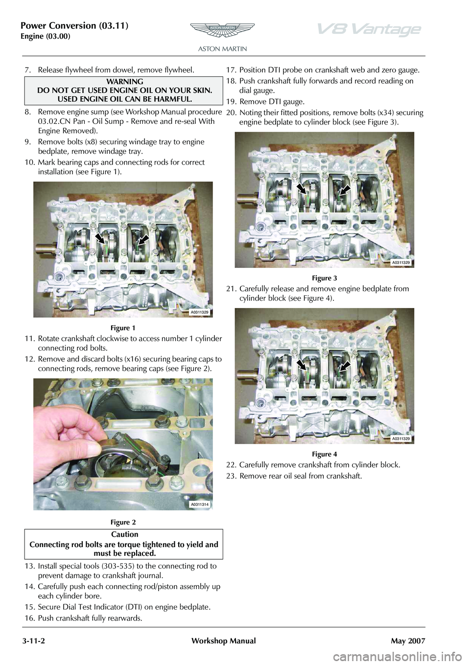
10. Mark bearing caps and connecting rods for correct installation (see Figure 1).
Figure 1
11. Rotate crankshaft clockwise to access number 1 cylinder
connecting rod bolts.
12. Remove and discard bolts (x16) securing bearing caps to connecting rods, remove bearing caps (see Figure 2).
Figure 2
13. Install special tools (303-535) to the connecting rod to prevent damage to crankshaft journal.
14. Carefully push each connecting rod/piston assembly up each cylinder bore.
15. Secure Dial Test Indicator (DTI) on engine bedplate.
16. Push crankshaft fully rearwards. 17. Position DTI probe on cran
kshaft web and zero gauge.
18. Push crankshaft fully forw ards and record reading on
dial gauge.
19. Remove DTI gauge.
20. Noting their fitted positions, remove bolts (x34) securing engine bedplate to cylinder block (see Figure 3).
Figure 3
21. Carefully release and remove engine bedplate from cylinder block (see Figure 4).
Figure 4
22. Carefully remove crankshaft from cylinder block.
23. Remove rear oil seal from crankshaft.
WAR NI NG
DO NOT GET USED ENGINE OIL ON YOUR SKIN.
USED ENGINE OIL CAN BE HARMFUL.
Caution
Connecting rod bolts are tor que tightened to yield and
must be replaced.
A0311329
A0311314
A0311329
A0311329
Page 392 of 947

Power Conversion (03.11)
Engine (03.00)3-11-20 Workshop Manual May 2007
16.Release harness clips (x6) from sump (see Figure 8).
Figure 8
17. Remove bolts (x4) securing LH and RH HEGO sensor
multiplug brackets to sump (see Figure 9).
Figure 9
18. Disconnect multiplug from A/C compressor. 19. Remove bolts (x4) securing A/C compressor to mounting
bracket. Remove compressor.
20. Remove bolts (x2) securing inlet and outlet oil pipes to sump (see Figure 10).
Figure 10
21. Release both oil pipes together from sump, remove and discard O-ring seals from pipes.
22. Remove Torx bolts (x4) securing A/C compressor mounting bracket to engine bedplate and sump.
Remove bracket (see Figure 11).
Figure 11
A030206B
A030206C
A030247
A0302303
Page 393 of 947

Power Conversion (03.11)
Engine (03.00)
May 2007 Workshop Manual 3-11-21
23. Remove bolts (x16) securing sump to engine bedplate
(see Figure 12).
Figure 12
24. Release and remove sump.
25. Remove bolts (x8) securing windage tray to engine bedplate, remove windage tray.
26. Mark bearing caps and connecting rods for correct installation (see Figure 13).
Figure 13
27. Rotate crankshaft clockwis e to access number 1 cylinder
connecting rod bolts. 28. Remove and discard bolts (x
16) securing bearing caps to
connecting rods, remove bearing caps (see Figure 14).
Figure 14
29. Install special tools (303-535) to the connecting rod to prevent damage to crankshaft journal.
30. Carefully push each conne cting rod/piston assembly
upwards and remove from cylinder block.
31. Remove special tools from connecting rods.
32. Install bearing caps on connecting rods, install and lightly tighten retaining bolts.
33. Note that piston grade number on crown and thick
flange on connecting rod faces to front of engine on RH
bank (A) (see Figure 15).
Figure 15
A030206D
A0311329
Caution
Connecting rod bolts are tor que
tightened to yield and
mu st
be replaced.
A0311314
A0311332
Page 394 of 947

Power Conversion (03.11)
Engine (03.00)3-11-22 Workshop Manual May 2007
34. Note that piston grade number on crown and thick
flange on connecting rod faces to front of engine on LH
bank (B) (see Figure 16).
Figure 16
Installation
1. Clean cylinder bores.
2. Use an expander and remove and discard piston rings from pistons.
3. Clean pistons.
4. Install new piston rings, (each set), in cylinder bores to a pre-determined depth and measure ring gaps.
5. Remove each piston ring set from cylinder bores and install on pistons
6. Remove connecting rod bearing caps.
7. Install bearings in connecting rods and bearing caps.
8. Lubricate cylinder bores, pistons and rings with clean
engine oil.
9. Install special tools (303-303-535) to the connecting rod to prevent damage to crankshaft journal.
10. Correctly position ring gaps on pistons prior to
installation. 11. Install piston ring clamp to each piston in turn and install
in its respective cylinder bore. Remove piston ring
clamp (see Figure 17).
Figure 17
12. Lubricate crankshaft journa ls with clean engine oil.
13. Carefully pull each connecting rod into place on each crankshaft journal.
14. Install bearing caps to their relevant connecting rods. Install and torque tighten retaining bolts (x16).
15. Clean windage tray.
16. Install windage tray, install and torque tighten bolts (x8).
17. Clean old sealant from sump flange and engine bedplate.
18. Ensure that sump flange and mating face on engine bedplate are clean and dry.
19. Apply a continuous 3mm diameter bead of RTV sealant to sump flange as recommended.
20. Ensure that there are no gaps in sealant track.
21. Install sump, install and torque tighten bolts (x16) in the correct sequence.
22. Install A/C compressor mounting bracket, install and torque tighten Torx bolts (x4).
23. Lubricate and install new O-ring seals to oil pipes.
24. Install oil pipes in sump, install and torque tighten bolts (x2)
25. Install compressor, install and torque tighten bolts (x4).
26. Connect multiplug to A/C compressor.
27. Install LH and RH HEGO sensor multiplug brackets to
sump. Install and torque tighten bolts (x4).
28. Secure harness clips (x6) in sump.
29. Connect multiplug to crankshaft timing sensor.
30. Connect multiplug to engine electric coolant temperature sensor.
31. Connect multiplug to oil pressure sensor.
Caution
Make sure the piston ring gaps are positioned at
different positions opposite th e thrust side of the piston
before installation.
A0311332
Caution
Install pistons into cylinder block with the
Page 395 of 947

Power Conversion (03.11)
Engine (03.00)
May 2007 Workshop Manual 3-11-23
32. Clean oil scavenge pump and mating face on sump.
33. Install oil pump(s) drive sprocket.
34. Install new oil scavenge pump gasket, align on dowels
(x2).
35. Install chain onto oil scavenge pump sprocket.
36. Install oil scavenge pump, al ign to dowels (x2), Install
and torque tighten bolts (x3).
37. Install chain onto oi l pump drive sprocket.
38. Clean oil pressure pump and mating face on sump.
39. Install new gasket to sump, align to dowels (x2).
40. Position oil pressure pu mp, install chain on pump
sprocket.
41. Install oil pressure pump, align to dowels (x2), Install and
torque tighten bolts (x3).
42. Install chain tensioner, install and torque tighten bolt, remove guide pin.
43. Install crankshaft timing sprocket.
44. Install cylinder head gaskets - engine set (see Workshop Manual procedure 03.01.HW Gasket - Cylinder Head -
Engine Set - Renew With Engine Removed).
Piston Ring-One Piston Set-Renew
Removal
1. Remove cylinder head gaskets - engine set (see Workshop Manual procedure 03.01.HW Gasket -
Cylinder Head - Engine Set - Renew With Engine
Removed).
2. Remove crankshaft timing sprocket from crankshaft.
3. Install guide pin through lower hole on chain tensioner.
4. Remove bolt securing oil pr essure pump chain tensioner
assembly to engine bedplate (see Figure).
Figure
5. Remove tensioner assembly.
6. Remove bolts (x3) securing oil pressure pump to sump.
7. Release chain from oil pressure pump sprocket, remove oil pump. 8. Remove and discard oil pressure pump gasket.
9. Remove bolts (x3) securing
oil scavenge pump to sump
(see Figure 2).
Figure 2
10. Release chain from oil scavenge pump sprocket, remove scavenge pump.
11. Remove and discard oil scavenge pump gasket (see Figure 3).
Figure 3
12. Remove oil pump(s) drive sprocket.
13. Disconnect multiplug from oil pressure sensor (see
Figure 4).
Figure 4
Repair Operation Time (ROT)
WA R N I N G
DO NOT GET USED ENGINE OIL ON YOUR SKIN. USED ENGINE OIL CAN BE HARMFUL.
A0302274
A0302274B
A0302276
A030216
Page 396 of 947

Power Conversion (03.11)
Engine (03.00)3-11-24 Workshop Manual May 2007
14.Disconnect multiplug from engine electric coolant
temperature sensor (see Figure 5).
Figure 5
15. Disconnect multiplug from crankshaft timing sensor. (see Figure 6)
Figure 6
16.Release harness clips (x6) from sump (see Figure 7).
Figure 7
A030216A
A030206
A030206B