Crankshaft sensor ASTON MARTIN V8 VANTAGE 2010 Workshop Manual
[x] Cancel search | Manufacturer: ASTON MARTIN, Model Year: 2010, Model line: V8 VANTAGE, Model: ASTON MARTIN V8 VANTAGE 2010Pages: 947, PDF Size: 43.21 MB
Page 234 of 947

3-0-2 Workshop Manual Issue 5, January 2010
Drive Belt-Renew ...................................................5-1
Engine Drive Belt and Bracket Assembly Oil Pump
Tensioner-Renew ...................................................5-1
Idler Pulley-Renew .................................................5-2
Engine Drive Belt Idler Assembly-Renew ................5-2
Engine Cranking System (03.06) ........................... 3-6-1 Maintenance ...........................................................6-1 Starter Motor-Renew ..............................................6-1
Ignition System (03.07) ......................................... 3-7-1 Maintenance ...........................................................7-1 Coil Assembly-Engine Set - LH-Renew ....................7-1
Emission Control (03.08) ...................................... 3-8-1 Maintenance ...........................................................8-1 Vacuum Outlet Hose Assemb ly-Renew ..................8-1
Secondary Air Injection Pump Tube-Renew............8-1
Vacuum System Reservoir and Bracket Assembly
- Renew .................................................................8-1
Oil Tank Breather Hose-Renew ..............................8-1
Air Cleaner to Rocker Cover Hose-Renew ..............8-1
Oil Separator Tube Assembly-Renew ......................8-1
Oil Separator Assembly-Renew...............................8-2
Emissions Separator Hose-Renew ...........................8-2
Secondary Air Injection Pump and Bracket
Assembly-Renew ....................................................8-2
PCV Valve Assembly-Renew ...................................8-2
Crank Vent Hose-Renew ........................................8-3
Exhaust Valve to Exhaust Manifold Tube Assembly
- Renew .................................................................8-3
Oil Separator to Inlet Manifold Hose- Renew .........8-3
EGR Module-Renew...............................................8-3
Valve Train (03.09)................................................ 3-9-1 Specifications ..........................................................9-1
Maintenance ...........................................................9-1 Left Side Timing Chain Arm Assembly - Remove
and Install ..............................................................9-1
Right Side Timing Chain Arm Assembly - Remove
and Install ..............................................................9-8
RH/LH Secondary Tensioner Assembly - Remove
and Install ............................................................9-14
Right and Left Intake Camshaft - Remove
and Install ............................................................9-15
Right and Left Exhaust Camshaft - Remove
and Install ............................................................9-17
RH/LH Secondary Timing Chain-Renew ...............9-18
RH/LH Secondary Tensioner Assembly-Renew
(with Engine Removed).........................................9-19
RH/LH Intake Camshaft Renew With Engine
Removed .............................................................9-20
RH/LH Exhaust Camshaft-Renew (with Engine
Removed) ............................................................9-22
RH/LH Secondary Timing Chain-Renew (with
Engine Removed) .................................................9-24
RH/LH Intake Camshaft Sprocket and Housing Assembly-
Renew......................................................................9-25 Left Side Primary Chain - Re move and Install).......9-26
RH/LH Intake Camshaft Sprocket and Housing
Assembly-Renew (with Engine Removed) .............9-29
Engine Sealing (03.10) ........................................ 3-10-1 Specifications ........................................................10-1 Maintenance ......................................................... 10-1
Engine Timing Cover - Renew .............................. 10-1
Left Side Cam Cover - Remove and Install ............ 10-4
Left Side Cam Cover Gasket - Renew ................... 10-5
Right Side Cam Cover Gasket - Renew ................. 10-6
Cylinder Head Gasket - Renew (Engine Set) ......... 10-6
Right Side Cam Cover - Remove and Install .......... 10-9
Cam Cover - Vehicle Set - Remove and Install .... 10-10
Engine Timing Cover- Renew (with Engine
Removed) .......................................................... 10-11
John Guest Cartridge in the Engine Timing Cover
- Repair .............................................................. 10-14
Power Conversion (03.11) ...................................3-11-1 Maintenance ......................................................... 11-1 Connecting Rod Bearing-Renew (Engine Set) ........ 11-1
Crankshaft Main Bearing-Renew (Engine Set)........ 11-1
Crankshaft Assembly-Renew................................. 11-4
Piston-Renew (Engine Set) .................................... 11-7
Piston-Renew ..................................................... 11-12
Additional Piston-Renew (E ach) .......................... 11-17
Piston Ring-Renew (Engine Set) .......................... 11-18
Piston Ring-One Piston Se t-Renew ..................... 11-23
Piston Ring Set-Additional -Renew (Each) ............ 11-28
Connecting Rod-Renew (Engin e Set) .................. 11-29
Crankshaft Damper Pulley Assembly-Renew ....... 11-34
Crankshaft Front Oil Seal-R enew ........................ 11-35
Rear Oil Crankshaft Seal-Renew ......................... 11-36
Cylinder Block-Renew........................................ 11-36
Crankshaft Damper Pulley Assembly-Renew
(with Engine Removed) ...................................... 11-37
Crankshaft Front Oil Seal-Renew (with
Engine Removed) ............................................... 11-37
Crankshaft Rear Oil Seal-Renew (with
Engine Removed) ............................................... 11-38
Air Charging (03.12) .......... ..................................3-12-1
Maintenance ......................................................... 12-1 Clean Air Duct - Remove and Install ..................... 12-1
Engine Air Filter - Remove and Install ................... 12-1
Engine Air Cleaner Assembly - Remove
and Install ............................................................ 12-2
Evaporative Emissions (03.13 ) .............................3-13-1
Description ........................................................... 13-1 System Operation ................................................ 13-1
Engine Management System (03.14) ...................3-14-1 Maintenance ......................................................... 14-1 Right Engine Control Module - Renew.................. 14-1
LH Front Lower Heated Exhaust Gas Oxygen
(HEGO) Sensor - Renew....................................... 14-1
LH Front Upper Heated Exhaust Gas Oxygen
(HEGO) Sensor - Renew....................................... 14-1
RH Front Upper Heated Exhaust Gas Oxygen
(HEGO) Sensor - Renew....................................... 14-2
RH Rear Lower Heated Exhaust Gas Oxygen
(HEGO) Sensor - Renew....................................... 14-2
Left Side Powertrain Control Module (PCM)
(Coupe Only) - Remove and Install....................... 14-3
Left Side Powertrain Control Module (PCM)
(Roadster Only) - Remove and Install.................... 14-4
Page 251 of 947

Engine Structure (03.01)
Issue 4, November 2008Workshop Manual 3-1-3
Knock Sensors
Two knock sensors (1) are installed into the cylinder block on the inboard side of each of the two cylinder banks. The
electrical connector of each sensor is secured to th e left-hand engine cover bracket (Refer to Figure 4).
These piezo-electric sensors send inputs to the ECM to indicate the detection and location of detonation during
combustion.
Bedplate
This is a structural casting that is attached with bolts to the bottom
of the cylinder block t attach the crankshaft and to further
improve overall rigidity.
Main bearing clearance changes due to expansion are minimized
by means of iron inserts cast into the bedplate main bearing
supports.
Two hollow dowels align the bedplate with the cylinder block and
the joint is sealed by a continuous bead of sealant.
Engine Mountings
The engine is mounted at two points. At the front, on ea ch side of the engine, there is a mounting bracket with a
Hydramount mounted to the subframe.
E 43437
Page 276 of 947
Lubrication System (03.02)
Engine (03.00)3-2-2 Workshop Manual Issue 5, Janauary 2010
Specifications
Engine Oil Specification
Maintenance
Oil Pressure Pump to Sump Gasket -
Renew
1. Remove crankshaft timing chain sprocket (refer to Workshop Manual procedure 03.09.AK Sprocket -
Crankshaft - Renew).
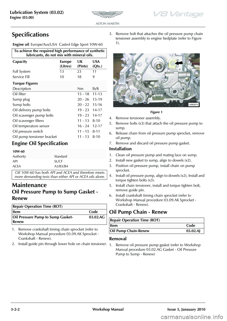
2. Install guide pin through lower hole on chain tensioner. 3. Remove bolt that attaches
the oil pressure pump chain
tensioner assembly to engine bedplate (refer to Figure
1).
4. Remove tensioner assembly.
5. Remove bolts (x3) that attach the oil pressure pump to sump.
6. Release chain from oil pres sure pump sprocket, remove
oil pump.
7. Remove and discard oil pressure pump gasket.
Installation
1. Clean oil pressure pump and mating face on sump.
2. Install new gasket to sump, align to dowels (x2).
3. Position oil pressure pump, install chain on pump sprocket.
4. Install oil pressure pump, align to dowels (x2), Install and torque tighten bolts (x3).
5. Install chain tensioner, install and torque tighten bolt, remove guide pin.
6. Install crankshaft timing chain sprocket (refer to Workshop Manual procedure 03.09.AK Sprocket -
Crankshaft - Renew).
Oil Pump Chain - Renew
Removal
1. Remove oil pressure pump gasket (refer to Workshop Manual procedure 03.02.AG Gasket - Oil Pressure
Pump to Sump - Renew)
Engine oil
Europe/Aus/USA Castrol Edge Sport 10W-60
To achieve the required high performance of synthetic
lubricants, do not mi x with mineral oils.
Capacity Europe (Litres)UK
(Pints)USA
(Qts.)
Full System 13 23 11
Service Fill 10 18 9
Torque Figures
DescriptionNmlb/ft
Oil filter 15 - 18 11-13
Sump plug 20 - 26 15-19
Sump bolts 20 - 22 15-16
Oil delivery pump bolts 19 - 23 14-17
Oil scavenger pump bolts 19 - 23 14-17
Oil scavenger filters 11 - 13 8-10
Oil temperature sensor 16 - 24 12-17
Oil pressure switch 11 - 15 8-11
Oil pump tensioner bracket 11 - 13 8-10
10W-60
AuthorityStandard
API SL/CF
ACEA A3/B3/B4
Oil 10W-60 has both API and ACEA and therefore meets
more demanding tests than eith er API or ACEA oils alone.
Repair Operation Time (ROT)
Figure 1
Repair Operation Time (ROT)
ItemCode
Oil Pump Chain-Renew 03.02.AJ
A0302274
Page 277 of 947

Lubrication System (03.02)
Engine (03.00)
Issue 5, Janauary 2010 Workshop Manual 3-2-3
2. Remove bolts (x3) that attach the oil scavenge pump to sump (refer to Figure 1).
3. Remove oil scavenge pump, remove and discard gasket (refer to Figure 2).
4. Release chain from oil pu mp drive sprocket, remove
chain (refer to Figure 3).Installation
1. Clean oil scavenge pump and mating face on sump.
2. Install new oil scavenge pump gasket, align on dowels (x2).
3. Install chain onto oil scavenge pump sprocket.
4. Install oil scavenge pump, align to dowels (x2), Install and torque tighten bolts (x3).
5. Install chain onto oil pump drive sprocket.
6. Install oil pressure pump gasket (refer to Workshop
Manual procedure 03.02.AG Gasket - Oil Pressure
Pump to Sump - Renew).
Oil Sump Pan - Renew
Removal
1. Remove oil sump (refer to Workshop Manual procedure
03.02.BN Pan - Oil Sump - Remove and Reseal).
2. Remove bolt that attach the crankshaft timing sensor, remove sensor (refer to Figure 1).
Figure 1
Figure 2
Figure 3
A0302274
A0302276
Repair Operation Time (ROT)
A0302305
Page 279 of 947

Lubrication System (03.02)
Engine (03.00)
Issue 5, Janauary 2010 Workshop Manual 3-2-5
8. Press out alternator mounting bushes (x2) from sump (refer to Figure 7).
9. Remove dowels (x4) from sump for oil pressure and scavenge pumps location (refer to Figure 8). 10. Remove Torx screws (x2) that attach the oil pump(s)
chain guide, remove chain gu ide (refer to Figure 9).
11. Remove oil plug from sump.
Installation
1. Clean chain guide, oil filter adaptor, filters (x2), sump plug , pump(s) dowels and crankshaft timing sensor.
2. Install alternator bushes.
3. Install oil filter adaptor.
4. Install filters (x2), install oil filter plates (x2), install and
torque tighten Torx screws (x4).
5. Install oil plug.
6. Install oil pump(s) dowels (x4).
7. Clean old sealant from sensor threads (x2).
8. Apply sealant to engine electric coolant temperature sensor threads, install and torque tighten sensor.
9. Apply sealant to oil pressure sensor threads, install and torque tighten sensor.
10. Install oil pump(s) chain guid e, Install and torque tighten
Torx screws (x2).
11. Install crankshaft timing sensor, install and torque tighten bolt.
12. Install oil sump (refer to Workshop Manual procedure 03.02.BN Pan - Oil Sump - Remove and Reseal).
Oil Sump Pan - Remove and Reseal
Removal
1. Remove oil pump(s) drive chain (refer to Workshop Manual procedure 03.02.AJ Chain - Oil Pump - Renew).
Figure 7
Figure 8
A030206C
A0302307
Figure 9
Repair Operation Time (ROT)
A0302307A
Page 280 of 947
Lubrication System (03.02)
Engine (03.00)3-2-6 Workshop Manual Issue 5, Janauary 2010
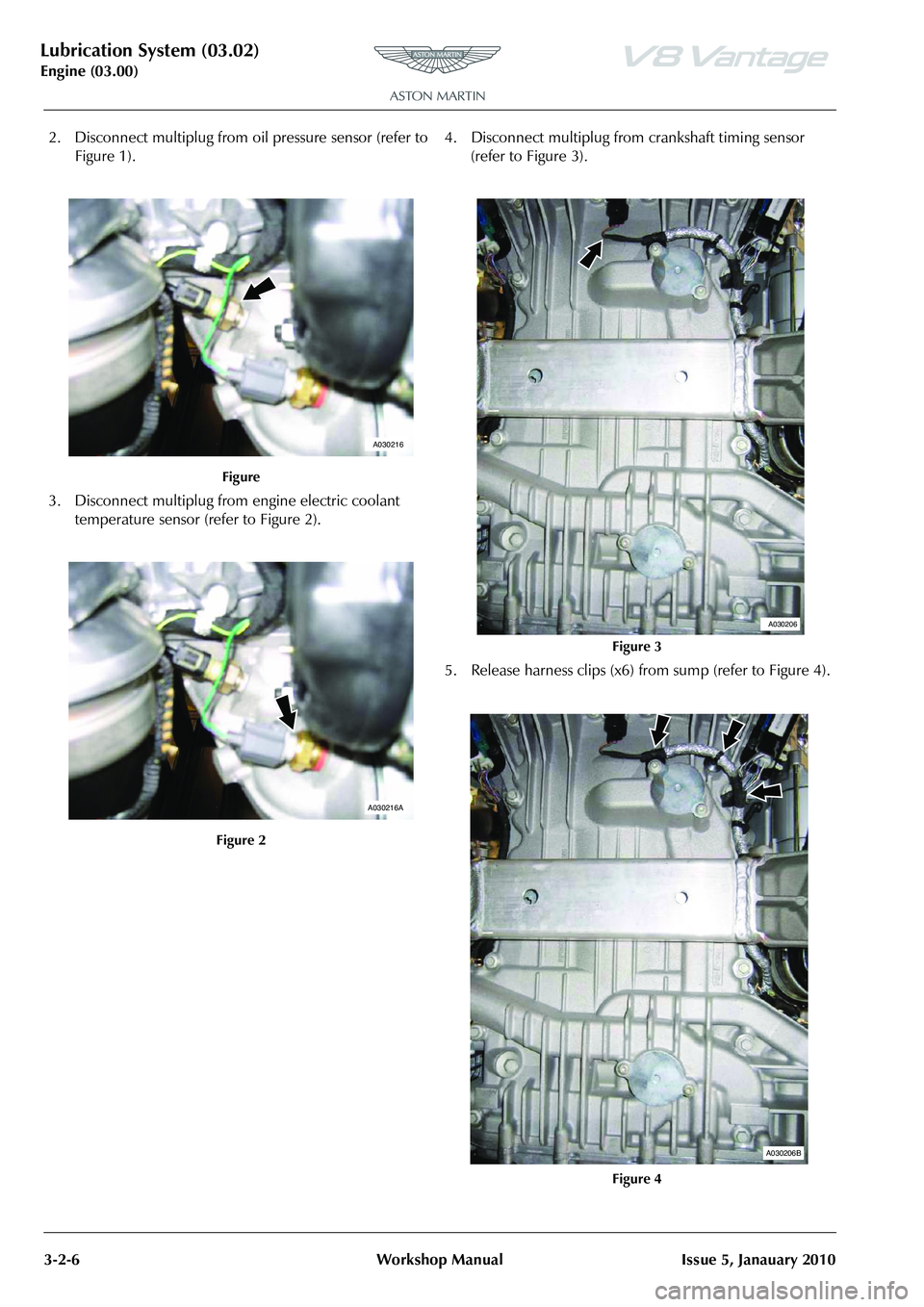
2. Disconnect multiplug from oi l pressure sensor (refer to
Figure 1).
3. Disconnect multiplug from engine electric coolant
temperature sensor (refer to Figure 2). 4. Disconnect multiplug from
crankshaft timing sensor
(refer to Figure 3).
5. Release harness clips (x6) from sump (refer to Figure 4).
Figure
Figure 2
A030216
A030216A
Figure 3
Figure 4
A030206
A030206B
Page 282 of 947
Lubrication System (03.02)
Engine (03.00)3-2-8 Workshop Manual Issue 5, Janauary 2010
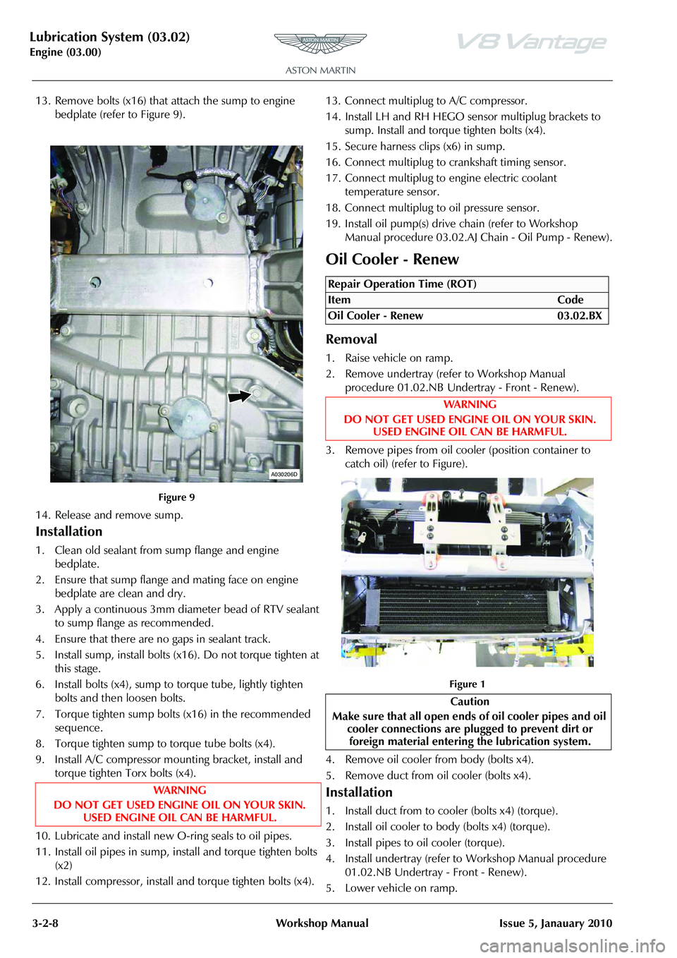
13. Remove bolts (x16) that attach the sump to engine bedplate (refer to Figure 9).
14. Release and remove sump.
Installation
1. Clean old sealant from sump flange and engine bedplate.
2. Ensure that sump flange and mating face on engine bedplate are clean and dry.
3. Apply a continuous 3mm diameter bead of RTV sealant to sump flange as recommended.
4. Ensure that there are no gaps in sealant track.
5. Install sump, install bolts (x16). Do not torque tighten at this stage.
6. Install bolts (x4), sump to torque tube, lightly tighten bolts and then loosen bolts.
7. Torque tighten sump bolts (x16) in the recommended sequence.
8. Torque tighten sump to torque tube bolts (x4).
9. Install A/C compressor mounting bracket, install and torque tighten Torx bolts (x4).
10. Lubricate and install new O-ring seals to oil pipes.
11. Install oil pipes in sump, install and torque tighten bolts (x2)
12. Install compressor, install and torque tighten bolts (x4). 13. Connect multiplug to A/C compressor.
14. Install LH and RH HEGO
sensor multiplug brackets to
sump. Install and torque tighten bolts (x4).
15. Secure harness clips (x6) in sump.
16. Connect multiplug to crankshaft timing sensor.
17. Connect multiplug to engine electric coolant temperature sensor.
18. Connect multiplug to oil pressure sensor.
19. Install oil pump(s) drive chain (refer to Workshop
Manual procedure 03.02.AJ Chain - Oil Pump - Renew).
Oil Cooler - Renew
Removal
1. Raise vehicle on ramp.
2. Remove undertray (refer to Workshop Manual procedure 01.02.NB Undertray - Front - Renew).
3. Remove pipes from oil cooler (position container to catch oil) (refer to Figure).
Figure 1
4. Remove oil cooler from body (bolts x4).
5. Remove duct from oil cooler (bolts x4).
Installation
1. Install duct from to cooler (bolts x4) (torque).
2. Install oil cooler to body (bolts x4) (torque).
3. Install pipes to oil cooler (torque).
4. Install undertray (refer to Workshop Manual procedure 01.02.NB Undertray - Front - Renew).
5. Lower vehicle on ramp.
Figure 9
WAR NI NG
DO NOT GET USED ENGINE OIL ON YOUR SKIN. USED ENGINE OIL CAN BE HARMFUL.
A030206D
Repair Operation Time (ROT)
ItemCode
Oil Cooler - Renew 03.02.BX
WAR NI NG
DO NOT GET USED ENGINE OIL ON YOUR SKIN. USED ENGINE OIL CAN BE HARMFUL.
Caution
Make sure that all open ends of oil cooler pipes and oil cooler connections are plugged to prevent dirt or
foreign material entering the lubrication system.
Page 289 of 947
Lubrication System (03.02)
Engine (03.00)
Issue 5, Janauary 2010 Workshop Manual 3-2-15
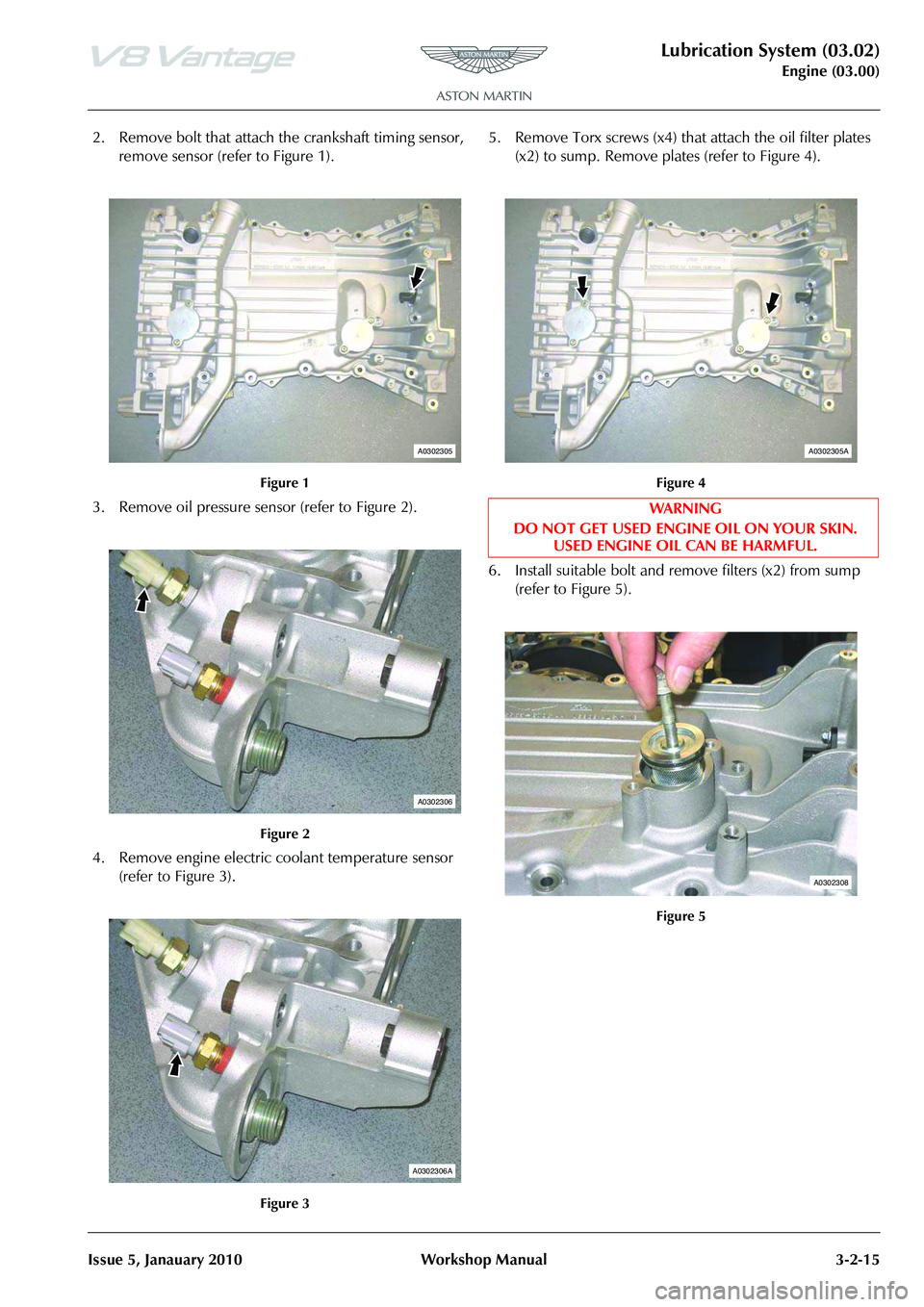
2. Remove bolt that attach the crankshaft timing sensor, remove sensor (refer to Figure 1).
3. Remove oil pressure sens or (refer to Figure 2).
4. Remove engine electric coolant temperature sensor (refer to Figure 3). 5. Remove Torx screws (x4) that
attach the oil filter plates
(x2) to sump. Remove plates (refer to Figure 4).
6. Install suitable bolt and re move filters (x2) from sump
(refer to Figure 5).
Figure 1
Figure 2
Figure 3
A0302305
A0302306
A0302306A
Figure 4
WA R N I N G
DO NOT GET USED ENGINE OIL ON YOUR SKIN. USED ENGINE OIL CAN BE HARMFUL.
Figure 5
A0302305A
A0302308
Page 290 of 947
Lubrication System (03.02)
Engine (03.00)3-2-16 Workshop Manual Issue 5, Janauary 2010
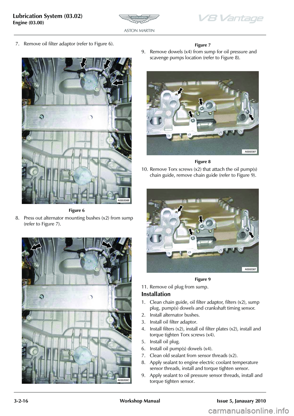
7. Remove oil filter adaptor (refer to Figure 6).
8. Press out alternator mounting bushes (x2) from sump (refer to Figure 7). 9. Remove dowels (x4) from
sump for oil pressure and
scavenge pumps location (refer to Figure 8).
10. Remove Torx screws (x2) that attach the oil pump(s)
chain guide, remove chain gu ide (refer to Figure 9).
11. Remove oil plug from sump.
Installation
1. Clean chain guide, oil filter adaptor, filters (x2), sump plug , pump(s) dowels and crankshaft timing sensor.
2. Install alternator bushes.
3. Install oil filter adaptor.
4. Install filters (x2), install oil filter plates (x2), install and
torque tighten Torx screws (x4).
5. Install oil plug.
6. Install oil pump(s) dowels (x4).
7. Clean old sealant from sensor threads (x2).
8. Apply sealant to engine electric coolant temperature sensor threads, install and torque tighten sensor.
9. Apply sealant to oil pressure sensor threads, install and torque tighten sensor.
Figure 6
A030206B
A030206C
Figure 7
Figure 8
Figure 9
A0302307
A0302307
Page 291 of 947
Lubrication System (03.02)
Engine (03.00)
Issue 5, Janauary 2010 Workshop Manual 3-2-17
10. Install oil pump(s) chain guid e, Install and torque tighten
Torx screws (x2).
11. Install crankshaft timing sensor, install and torque
tighten bolt.
12. Install oil sump (refer to Workshop Manual procedure
03.02.CN Pan - Oil Sump - Remove and Reseal With
Engine Removed).
Oil Sump Pan - Remove and Reseal (with
Engine Removed
)
Removal
1. Remove oil pump(s) drive chain (refer to Workshop Manual procedure 03.02.BJ Chain - Oil Pump - Renew
With Engine Removed).
2. Disconnect multiplug from oi l pressure sensor (refer to
Figure 1). 3. Disconnect multiplug from
engine electric coolant
temperature sensor (refer to Figure 2).
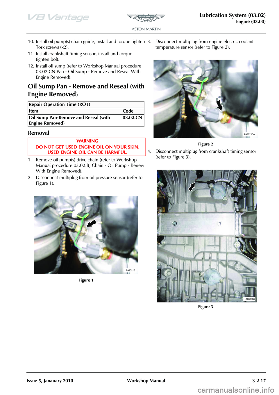
4. Disconnect multiplug from crankshaft timing sensor
(refer to Figure 3).
Repair Operation Time (ROT)
A030216
Figure 2
Figure 3
A030216A
A030206