change wheel ASTON MARTIN V8 VANTAGE 2010 Workshop Manual
[x] Cancel search | Manufacturer: ASTON MARTIN, Model Year: 2010, Model line: V8 VANTAGE, Model: ASTON MARTIN V8 VANTAGE 2010Pages: 947, PDF Size: 43.21 MB
Page 9 of 947
Lifting and Jacking
Issue 5, January 2010 Workshop Manual 0-0-9
Lifting and Jacking
Safety
•Recommended procedures for lifting, jacking and
towing must be strictly ob served to ensure personal
safety.
• Always use a vehicle hoist, ramp or pit for working
beneath the vehicle in preference to jacking.
• Never rely on a jack to supp ort a car independently, use
axle stands or blocks carefu lly placed at jacking points
to provide rigid support.
• When working beneath a vehicle, chock wheels as well
as applying handbrake.
• Ensure vehicle is standing on firm, level ground before
jacking or lifting.
• Check lifting equipment has adequate capacity for load
being lifted and is in full working order.
Jacking Points
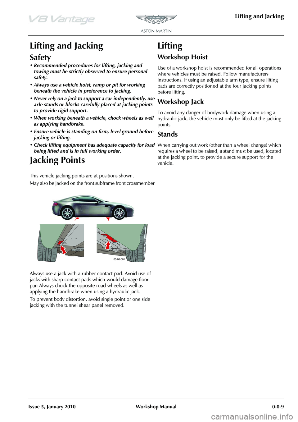
This vehicle jacking points are at positions shown.
May also be jacked on the front subframe front crossmember
Always use a jack with a rubber contact pad. Avoid use of
jacks with sharp contact pads which would damage floor
pan Always chock the opposite road wheels as well as
applying the handbrake when using a hydraulic jack.
To prevent body distortion, av oid single point or one side
jacking with the tunnel shear panel removed.
Lifting
Workshop Hoist
Use of a workshop hoist is recommended for all operations
where vehicles must be raised. Follow manufacturers
instructions. If using an adjustable arm type, ensure lifting
pads are correctly positioned at the four jacking points
before lifting.
Workshop Jack
To avoid any danger of bodywork damage when using a
hydraulic jack, the vehicle must only be lifted at the jacking
points.
Stands
When carrying out work (other than a wheel change) which
requires a wheel to be raised, a stand must be used, located
at the jacking point, to provide a secure support for the
vehicle.
00-00-001
Page 453 of 947
Road Wheels and Tyres (04.04)
Suspension (04.00)
May 2007 Workshop Manual 4-4-3
Maintenance
Factory installed tyres and road wheels are designed to
operate satisfactory when inflated to the recommended
inflation pressures (Refer to ’Inspection and Verification’,
page 4-4-4). The recommended pressures apply to vehicle
loads up to and including the full-rated load capacity.
Correct tyre pressures and driving technique have an
important influence on tyre life. Heavy cornering,
excessively rapid acceleration and unnecessary sharp
braking increase tyre wear.
Replacement tyres should follow the recommended:
The use of any other size or type may seriously affect:
Wheels need to be renewed when:
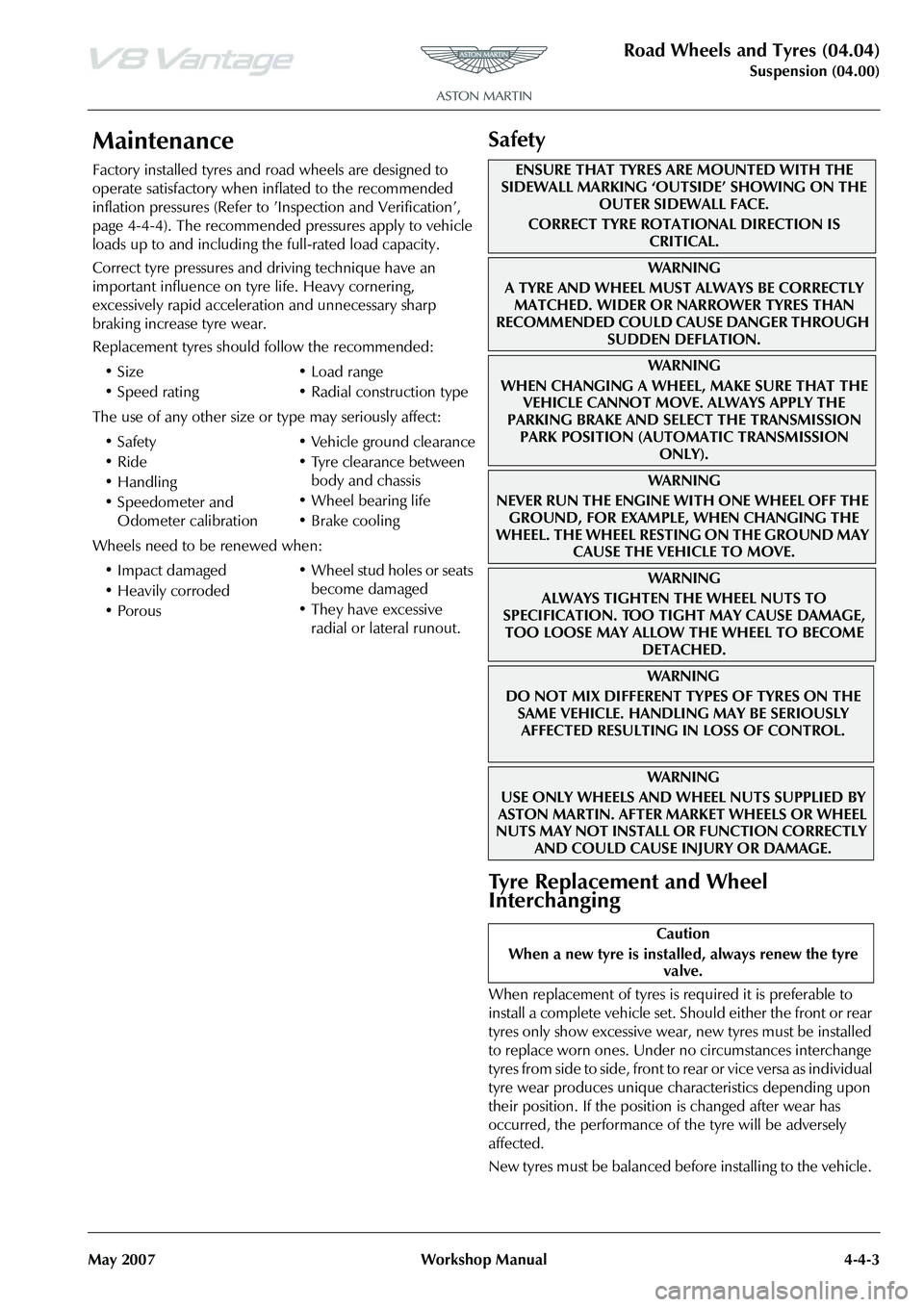
Safety
Tyre Replacement and Wheel
Interchanging
When replacement of tyres is required it is preferable to
install a complete vehicle set. S hould either the front or rear
tyres only show excessive wear, new tyres must be installed
to replace worn ones. Under no circumstances interchange
tyres from side to side, front to re ar or vice versa as individual
tyre wear produces unique characteristics depending upon
their position. If the position is changed after wear has
occurred, the performance of the tyre will be adversely
affected.
New tyres must be balanced before installing to the vehicle.
•Size
•Speed rating
•Load range
• Radial construction type
•Safety
•Ride
•Handling
• Speedometer and Odometer calibration • Vehicle ground clearance
• Tyre clearance between
body and chassis
• Wheel bearing life
• Brake cooling
• Impact damaged
• Heavily corroded
• Porous • Wheel stud holes or seats
become damaged
• They have excessive radial or lateral runout.
ENSURE THAT TYRES ARE MOUNTED WITH THE
SIDEWALL MARKING ‘OUTSIDE’ SHOWING ON THE
OUTER SIDEWALL FACE.
CORRECT TYRE ROTATIONAL DIRECTION IS CRITICAL.
WA R N I N G
A TYRE AND WHEEL MUST ALWAYS BE CORRECTLY MATCHED. WIDER OR NARROWER TYRES THAN
RECOMMENDED COULD CAUSE DANGER THROUGH
SUDDEN DEFLATION.
WA R N I N G
WHEN CHANGING A WHEEL, MAKE SURE THAT THE VEHICLE CANNOT MOVE. ALWAYS APPLY THE
PARKING BRAKE AND SELE CT THE TRANSMISSION
PARK POSITION (AUTOMATIC TRANSMISSION ONLY).
WA R N I N G
NEVER RUN THE ENGINE WITH ONE WHEEL OFF THE GROUND, FOR EXAMPLE, WHEN CHANGING THE
WHEEL. THE WHEEL RESTING ON THE GROUND MAY CAUSE THE VEHICLE TO MOVE.
WA R N I N G
ALWAYS TIGHTEN THE WHEEL NUTS TO
SPECIFICATION. TOO TIGHT MAY CAUSE DAMAGE,
TOO LOOSE MAY ALLOW TH E WHEEL TO BECOME
DETACHED.
WAR NI NG
DO NOT MIX DIFFERENT TY PES OF TYRES ON THE
SAME VEHICLE. HANDLING MAY BE SERIOUSLY AFFECTED RESULTING IN LOSS OF CONTROL.
WAR NI NG
USE ONLY WHEELS AND WHEEL NUTS SUPPLIED BY
ASTON MARTIN. AFTER MARKET WHEELS OR WHEEL
NUTS MAY NOT INSTALL OR FUNCTION CORRECTLY
AND COULD CAUSE INJURY OR DAMAGE.
Caution
When a new tyre is installe d, always renew the tyre
valve.
Page 455 of 947
Road Wheels and Tyres (04.04)
Suspension (04.00)
May 2007 Workshop Manual 4-4-5
Road Test
A tyre vibration diagnostic proc edure always begins with a road test. The road test and customer interview (if available)
will provide much of the information neede d to find the source of a vibration.
During the road test, drive the vehicle on a road that is smoot h and free of undulations. If vibration is apparent, note and
record the following:
• The speed at which the vibration occurs
• What type of vibration occurs in each speed range
• How the vibration is affected by changes in the following types of vibration-sensitivity:
Torque Sensitive - This means that the condition may be improved or made worse by accelerating, decelerating, coasting,
maintaining a steady vehicle speed or applying engine torque.
Vehicle Speed Sensitive - This means that the vibration always occurs at the same vehicle speed and is not affected by
engine torque, engine speed or the transmission gear selected.
Engine Speed Sensitive - This means that the vibration occurs at varyin g vehicle speeds when a different transmission
gear is selected. It may sometimes be isolated by increasing or decreasing engine speed with the transmission in NEUTRAL
or by stall testing with the transmission in gear. If the condition is engine speed sensitive, the cause is probably not relate d
to the tyres.
If the road test indicates that there is tyre whine, but no sh ake or vibration, the noise originates with the contact between
the tyre and the road surface.
A thumping noise usually means that the tyre has a flat or soft spot making a noise as they slap the roadway. Tyre whine
may be distinguished from axle noise. Tyre whine remains the same over a range of speeds.
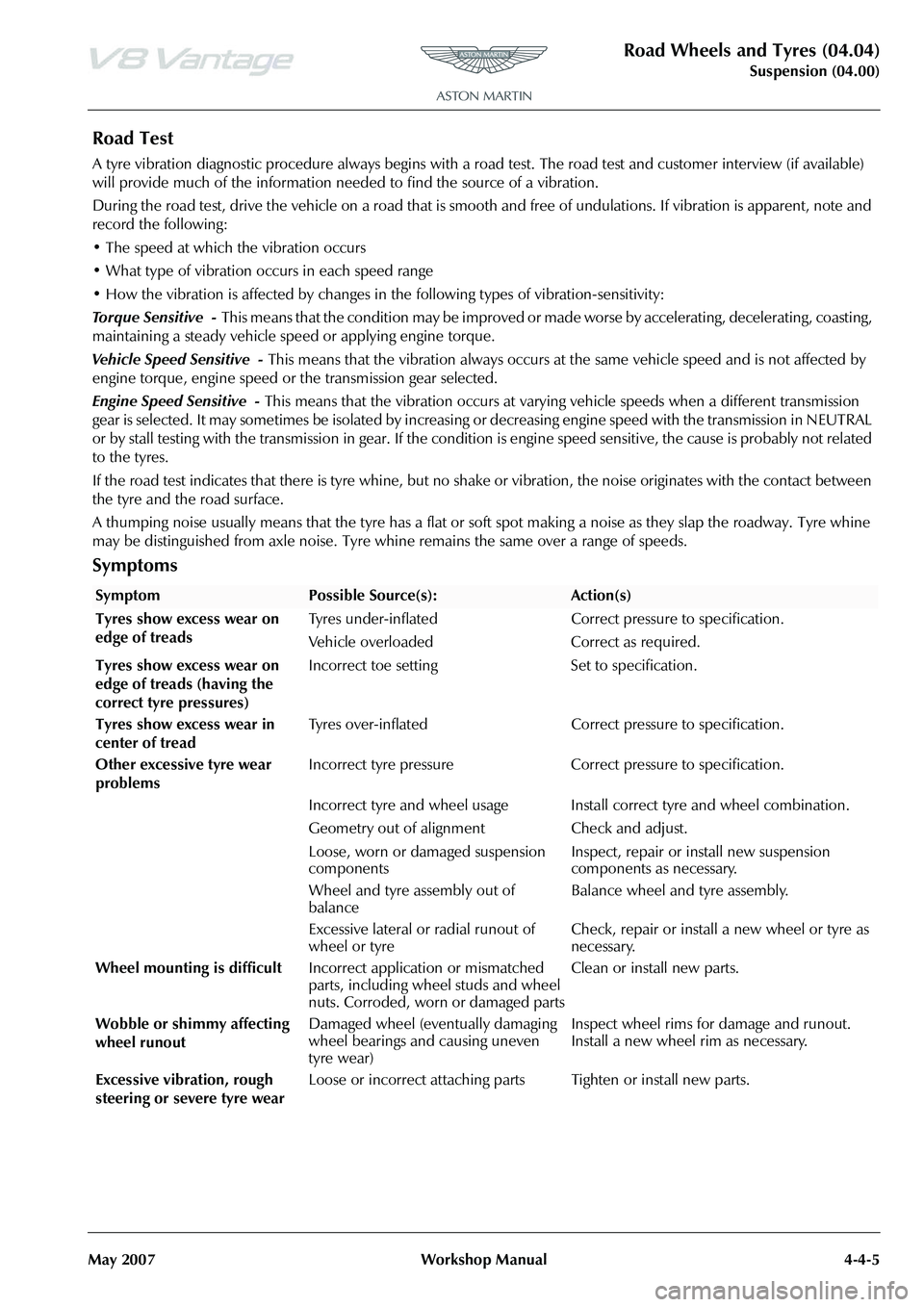
Symptoms
SymptomPossible Source(s):Action(s)
Tyres show excess wear on
edge of treads Tyres under-inflated Correct pressure to specification.
Vehicle overloaded Correct as required.
Tyres show excess wear on
edge of treads (having the
correct tyre pressures) Incorrect toe setting Set to specification.
Tyres show excess wear in
center of tread Tyres over-inflated Correct pressure to specification.
Other excessive tyre wear
problems Incorrect tyre pressure Correct pressure to specification.
Incorrect tyre and wheel usage Install correct tyre and wheel combination.
Geometry out of alignm
ent Check and adjust.
Loose, worn or damaged suspension
components Inspect, repair or install new suspension
components as necessary.
Wheel and tyre assembly out of
balance Balance wheel and tyre assembly.
Excessive lateral or radial runout of
wheel or tyre Check, repair or install a new wheel or tyre as
necessary.
Wheel mounting is difficult Incorrect application or mismatched
parts, including wheel studs and wheel
nuts. Corroded, worn or damaged parts Clean or install new parts.
Wobble or shimmy affecting
wheel runout Damaged wheel (eventually damaging
wheel bearings and causing uneven
tyre wear) Inspect wheel rims for damage and runout.
Install a new wheel rim as necessary.
Excessive vibration, rough
steering or severe tyre wear Loose or incorrect attaching parts Tighten or install new parts.
Page 461 of 947
Road Wheels and Tyres (04.04)
Suspension (04.00)
May 2007 Workshop Manual 4-4-11
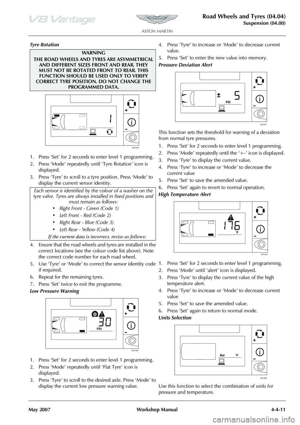
Tyre Rotation
1. Press ‘Set’ for 2 seconds to enter level 1 programming .
2. Press ‘Mode’ repeatedly until ‘Tyre Rotation’ icon is displayed.
3. Press ‘Tyre’ to scroll to a tyre position. Press ‘Mode’ to display the current sensor identity.
4. Ensure that the road wheels and tyres are installed in the correct locations (see the colour code list above). Note
the correct code number for each road wheel.
5. Use ‘Tyre’ or ‘Mode’ to co rrect the sensor identity code
if required.
6. Repeat for the remaining tyres.
7. Press ‘Set’ twice to exit the programme.
Low Pressure Warning
1. Press ‘Set’ for 2 seconds to enter level 1 programming .
2. Press ‘Mode’ repeatedly until ‘Flat Tyre’ icon is displayed.
3. Press ‘Tyre’ to scroll to th e desired axle. Press ‘Mode’ to
display the current low pressure warning value. 4. Press ‘Tyre’ to increase or
‘Mode’ to decrease current
value.
5. Press ‘Set’ to enter the new value into memory.
Pressure Deviation Alert
This function sets the threshold for warning of a deviation
from normal tyre pressures.
1. Press ‘Set’ for 2 seconds to enter level 1 programming .
2. Press ‘Mode’ repeatedly until the ‘+-’ icon is displayed.
3. Press ‘Tyre’ to display the current value.
4. Press ‘Tyre’ to increase or ‘Mode’ to decrease the
current value
5. Press ‘Set’ to save the amended value.
6. Press ‘Set’ again to revert to normal operation.
High Temperature Alert
1. Press ‘Set’ for 2 seconds to enter level 1 programming .
2. Press ‘Mode’ until ‘ale rt’ icon is displayed.
3. Press ‘Tyre’ to display the current value of the high temperature alert.
4. Press ‘Tyre’ to increase or ‘Mode’ to decrease current
value
5. Press ‘Set’ to save the amended value.
6. Press ‘Set’ again to return to normal mode.
Units Selection
Use this function to select the combination of units for
pressure and temperature.
WAR NI N G
THE ROAD WHEELS AND TYRES ARE ASYMMETRICAL AND DIFFERENT SIZES FRONT AND REAR. THEY
MUST NOT BE ROTATED FRONT TO REAR. THIS FUNCTION SHOULD BE USED ONLY TO VERIFY
CORRECT TYRE POSITION. DO NOT CHANGE THE PROGRAMMED DATA.
Each sensor is identified by th e colour of a washer on the
tyre valve. Tyres are always in stalled in fixed positions and
must remain as follows:
• Right Front - Green (Code 1)
• Left Front - Red (Code 2)
Page 462 of 947
Road Wheels and Tyres (04.04)
Suspension (04.00)4-4-12 Workshop Manual May 2007
1. Press ‘Set’ for 2 seconds to enter level 1 programming .
2. Press ‘Mode’ until pressure / temperature units are displayed.
3. Press ‘Tyre’ to enter ‘Units Selection’ mode.
4. Use ‘Tyre’ or ‘Mode’ to scroll through four combinations of pressure / temperature units.
5. Press ‘Set’ to save the selected combination of units.
6. Press the ‘Set’ button again to revert to normal mode.
Level 2 Programming
Slope
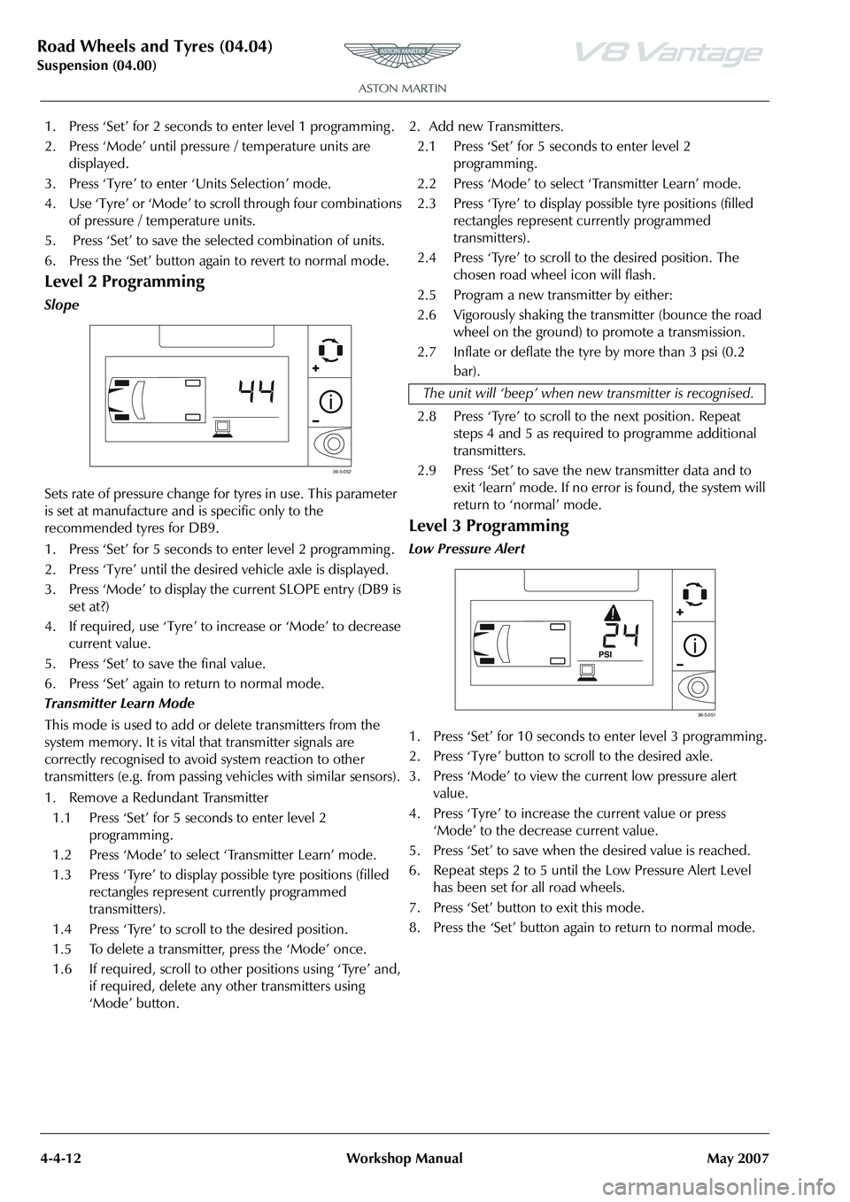
Sets rate of pressure change for tyres in use. This parameter
is set at manufacture and is specific only to the
recommended tyres for DB9.
1. Press ‘Set’ for 5 seconds to enter level 2 programming .
2. Press ‘Tyre’ until the desired vehicle axle is displayed.
3. Press ‘Mode’ to display the current SLOPE entry (DB9 is set at?)
4. If required, use ‘Tyre’ to increase or ‘Mode’ to decrease current value.
5. Press ‘Set’ to save the final value.
6. Press ‘Set’ again to return to normal mode.
Transmitter Learn Mode
This mode is used to add or delete transmitters from the
system memory. It is vital that transmitter signals are
correctly recognised to avoid system reaction to other
transmitters (e.g. from passing vehicles with similar sensors).
1. Remove a Redundant Transmitter 1.1 Press ‘Set’ for 5 seconds to enter level 2 programming .
1.2 Press ‘Mode’ to select ‘Transmitter Learn’ mode.
1.3 Press ‘Tyre’ to display possible tyre positions (filled rectangles represent currently programmed
transmitters).
1.4 Press ‘Tyre’ to scroll to the desired position.
1.5 To delete a transmitter, press the ‘Mode’ once.
1.6 If required, scroll to other positions using ‘Tyre’ and, if required, delete any other transmitters using
‘Mode’ button. 2. Add new Transmitters.
2.1 Press ‘Set’ for 5 seconds to enter level 2 programming .
2.2 Press ‘Mode’ to select ‘Transmitter Learn’ mode.
2.3 Press ‘Tyre’ to display possible tyre positions (filled rectangles represent currently programmed
transmitters).
2.4 Press ‘Tyre’ to scroll to the desired position. The chosen road wheel icon will flash.
2.5 Program a new transmitter by either:
2.6 Vigorously shaking the transmitter (bounce the road wheel on the ground) to promote a transmission.
2.7 Inflate or deflate the tyre by more than 3 psi (0.2 bar).
2.8 Press ‘Tyre’ to scroll to the next position. Repeat steps 4 and 5 as required to programme additional
transmitters.
2.9 Press ‘Set’ to save the new transmitter data and to exit ‘learn’ mode. If no error is found, the system will
return to ‘normal’ mode.
Level 3 Programming
Low Pressure Alert
1. Press ‘Set’ for 10 seconds to enter level 3 programming .
2. Press ‘Tyre’ button to scroll to the desired axle.
3. Press ‘Mode’ to view the current low pressure alert value.
4. Press ‘Tyre’ to increase the current value or press ‘Mode’ to the decrease current value.
5. Press ‘Set’ to save when the desired value is reached.
6. Repeat steps 2 to 5 until the Low Pressure Alert Level has been set for all road wheels.
7. Press ‘Set’ button to exit this mode.
8. Press the ‘Set’ button again to return to normal mode.
36-5-052
The unit will ‘beep’ when ne w transmitter is recognised.
36-5-051
Page 508 of 947
Anti-lock Braking System (ABS) (06.09)
Brake system (06.00)
6-9-2 Workshop Manual Issue 4, November 2008
difference between the ideal and actual response within a
tolerance band. This directly influences the forces on the
tires to generate a corrective yaw moment to reduce the side
forces of the tires where appropriate
System Overview
The DSC system embraces capabilities far beyond that of
ABS, or ABS and traction control combined, while relying on
the components of these systems. It also incorporates these
additional sensors for measur ing the vehicle’s motion and
brake system pressure:
Ya w r a t e s e n s o r - located centrally on the transmission
tunnel.
Lateral acceleration sensor - integrated with the yaw rate
sensor.
Steering angle sensor - located on the upper steering
column.
Pressure transducer - located on master cylinder.
The ABS / DSC module supports data exchange with other
vehicle electronic systems via the CAN network; the module
also enables diagnostic interrogation using WDS.
The following components register driver demand and the
ABS / DSC module processes their signals as a basis for
defining an ideal response:
PCM - position of accelerator pedal.
Brake master cylinder pressure transducer - driver’s
braking effort.
Steering angle sensor - position of steering wheel.
There are many supplementary parameters also included in
the processing calculations these include the coefficient of
friction and vehicle speed. The ABS / DSC module monitors
these factors based on signals transmitted by the sensors for:
• Wheel speed
• Lateral acceleration
• Brake pressure
• Yaw rate
Using these parameters, the function of the ABS / DSC
module is to determine the current vehicle status based on
the yaw-rate signal and the slip as estimated by the ABS /
DSC module. It then maintains the vehicle response within
a tolerance of the ‘normal’ behaviour, which is easily
controlled by the driver.
In order to generate the desired yaw behaviour the ABS /
DSC module controls the selected wheels using the ABS
hydraulic system and engine control system. In the event of
engine intervention, the ABS / DSC module calculates the
torque which should be supplied by the engine to the
wheels, and relays this request signal to the PCM which
implements the torque request.
The PCM receives signals from the DSC system via the CAN
bus and reduces engine torque as follows:
• The throttle is positioned to provide the requested engine target torque. • During the transient phase of torque reduction caused by
mechanical and combustion delays, other alternative
torque reduction methods are used to provide a quicker
response.
• The ignition is retarded and / or the fuel is cut-off at the injectors at selected cylinders.
• Ignition and fuelling are reinstated when the engine torque reaches the requested value
Operation Summary
• DSC is switched ‘ON’ when the engine is started
• When the system is operating , the DSC light in the instrument cluster will flash, at the rate of twice a second
• DSC can be switched ‘OFF / ON’ by pressing the DSC switch
• The DSC light in the instru ment cluster will illuminate
continuously when the system is switched ‘Off’.
• ‘DSC OFF’ will be displayed in the message centre right to indicate the system has been switched ‘OFF’
• A malfunction in the traction control system will be indicated to the driver by the following:
• The DSC light in the instru ment cluster will illuminate
continuously
• The message ‘DSC NOT AVAILABLE’ will be displayed in the message centre right
• If vehicle speed control is engaged it will automatically disengage when traction control is operating .
Traction Control
Traction control is a function of DSC, and is operated in
association with DSC. Traction control prevents excessive
wheel-spin at standing starts, or during acceleration. Wheel-
spin is usually caused by ex cessive use of the accelerator
pedal, or slippery, loose or bumpy road surfaces. To prevent
excessive wheel-spin and mainta in vehicle stability such
situations are overcome by the intervention of the traction
control system by:
• Braking the driven-wheel when it starts to slip
• And / or adapting the engine torque to a level corresponding to the traction available on the road
surface.
Functional Description
Traction control uses the ABS electronic and mechanical /
hydraulic hardware with additional valves to control the
braking pressure at the calipe rs. An engine interface also
enables the engine to respond to torque reduction requests
from the traction control. As with ABS, the signals from the
wheel-speed sensors are supplied to the ABS module, where
they are used to calculate the wheel-slip of the individual
wheels. Traction control intervention is initiated if the slip at
one of the wheels is excessive.
Page 602 of 947
Steering Gear (11.01)
Steering (11.00)
Issue 5, January 2010 Workshop Manual 11-1-3
Vehicle tends to pull
to one side when
driven on a level
surface. Incorrect tyre pressure. Adjust tyre pressure.
Incorrect tyre size.
Different tyre or tread type.
New tyre as required.
Vehicle is unevenly or excessively loaded. Adjust load evenly.
Incorrect toe adjustment. Adjust as required.
Damaged front or rear suspension
components. New suspension components.
Steering gear valve effort out of balance. Shift transmission into neutral while driving at no more than 30 miles/hour (50 km/h) and turn the
ignition to position I (engine ‘Off’-coasting).
a. If the vehicle does not pull to one side with the
engine off, install a new steering gear.
b. If the vehicle drifts with the engine off, ‘cross switch’ the front wheel assemblies.
Test at low speed due to directional tyres.
a. If the vehicle pulls to the opposite side, switch the wheels that were on the rear to the same
side on the front.
b. If the vehicle pull direction is not changed, check the front suspension components and
toe adjustments.
Check front and rear brakes for correct
operation. Adjust as required.
Check for bent rear suspension components
and for damaged coil springs in the front
suspension. New rear suspension components.
Check the rear suspension for loose or worn
suspension components. Tighten.
New components.
Incorrect underbody alignment. Check underbody alignment.
Feedback (whining
or knocking noises
in the steering gear)
Condition where
roughness is felt in
the steering wheel by
the driver when the
vehicle is driven over
rough surfaces. Loose or worn tie-rods. New steering gear.
Steering gear bolts loose or damaged. Tighten.
New bolts.
Loose suspension bushing , bolts or ball joints. Tighten.
New components.
Damaged steering column.
Loose Column bolts. New steering column.
Tighten bolts.
Power steering
pump or reservoir
leaks Overfilled system. Correct fluid level.
Damaged fluid cap. New fluid cap.
Loose or damaged hose fittings. Tighten.
New hose.
Leakage at power steering pump. New power steering pump.
Poor returnability of
the steering Incorrect tyre pressure. Check
and adjust tyre pressure.
Incorrect tyre size or ty pe. New tyre as required.
Steering column universal joints binding . New steering column.
Steering column shaft floor seal may be torn
and fouling I-shaft. New floor seal as required.
Binding or damaged tie-rods. New steering gear.
Damaged or worn front suspension
components. New front suspension components as required.
Incorrect toe adjustment. Adjust as required.
SymptomPossible CauseAction
Page 886 of 947

AML EOBD System Operation Summary
Rory O’Curry Aston Martin Lagonda CONFIDENTIAL 1 May 2009
[email protected] AML EOBD Monitors 07 ROC.doc Page 41 of 43
X P1431 Misfire Monitor Disabled; unable to Learn Trigger Wheel Profile
P1432 Thermostat Heater Control Circuit
P1460 Wide Open Throttle A/C Cut-out Circuit
P1461 A/C Pressure Sensor Circuit High Input
P1462 A/C Pressure Sensor Circuit Low Input
P1463 A/C Pressure Sensor Insufficient Pressure Change
P1464 A/C Demand Out of Self Test Range
P1500 Vehicle Speed Sensor
P1501 Vehicle Speed Sensor Out of Self Test Range
P1549 Intake Manifold Communica tion Control Circuit (Bank 1)
P1572 Brake system input failure (BLS failed then BPS failed)
P1610 Interactive Reprogramming Code – Replace Module
P1611 Interactive Reprogramming Code – Diagnose Further
P1615 Interactive Reprogramming Code – Erase Error
P1616 Interactive Reprogramming Code – Erase Error, Low Voltage
P1617 Interactive Reprogramming Code – Block Program Error
P1618 Interactive Reprogramming Code – Block Program Error, Low Voltage
P1631 Main Relay (Power Hold)
X P1633 Keep Alive Power Voltage too Low
P1635 Tyre/Axle Out of Acceptable Range
P1639 Vehicle Identification (VID) Block Corrupted. Not Programmed
X P1656 CAN Link PCM/PCM Circuit/Network
P1703 Brake switch out of self test range
P1709 Park/Neutral Position Switch Out of Self Test Range
X P2008 Intake Manifold Runner Control Open (Bank 1)
X P2100 Throttle Actuator Control Motor Circuit Open
X P2101 Throttle Actuator Control Motor Circuit Range/Performance
X P2107 Throttle actuator control motor processor
X P2110 Forced limit RPM mode
X P2111 Throttle actuator control system – stuck closed
X P2112 Throttle actuator control system – stuck open
P2121 Pedal position sensor D circuit range/performance
P2122 Pedal position sensor D circuit low input
P2123 Pedal position sensor D circuit high input
P2124 Pedal position sensor D circuit intermittent
P2126 Pedal position sensor E circuit range/performance
P2127 Pedal position sensor E circuit low input
P2128 Pedal position sensor E circuit high input
P2129 Pedal position sensor E circuit intermittent
P2135 Throttle position sensor A/B voltage correlation
P2138 Pedal position sensor D/E voltage correlation
X P2195 Lack of Heated Oxygen Sensor (Bank 1, Sensor 1) Switches, Sensor Indicates Lean
X P2196 Lack of Heated Oxygen Sensor (Bank 2, Sensor 1) Switches, Sensor Indicates Lean
X P2197 Lack of Heated Oxygen Sensor (Bank 1, Sensor 1) Switches, Sensor Indicates Rich
X P2198 Lack of Heated Oxygen Sensor (Bank 2, Sensor 1) Switches, Sensor Indicates Rich
Note.
X MIL codes
* Can be non-mil if below EOBD threshold.