low oil pressure ASTON MARTIN V8 VANTAGE 2010 Workshop Manual
[x] Cancel search | Manufacturer: ASTON MARTIN, Model Year: 2010, Model line: V8 VANTAGE, Model: ASTON MARTIN V8 VANTAGE 2010Pages: 947, PDF Size: 43.21 MB
Page 154 of 947
Convertible Roof (01.17)
Body System (01.00)1-12-16 Workshop Manual May 2007
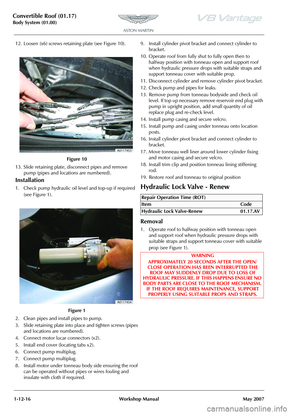
12. Loosen (x6) screws retain ing plate (see Figure 10).
13. Slide retaining plate, disconnect pipes and remove pump (pipes and locations are numbered).
Installation
1. Check pump hydraulic oil le vel and top-up if required
(see Figure 1).
2. Clean pipes and install pipes to pump.
3. Slide retaining plate into place and tighten screws (pipes and locations are numbered).
4. Connect motor lucar connectors (x2).
5. Install end cover (locating tabs x2).
6. Connect pump multiplug.
7. Connect pump multiplug.
8. Install motor under tonneau body side ensuring the roof can be operated without pipes or wires fouling and
insulate with cloth if required. 9. Install cylinder pivot bracket and connect cylinder to
bracket.
10. Operate roof from fully shut to fully open then to halfway position with tonneau open and support roof
when hydraulic pressure drop s with suitable straps and
support tonneau cover with suitable prop.
11. Disconnect cylinder and remove cylinder pivot bracket.
12. Check pump and pipes for leaks.
13. Remove pump from tonneau bodyside and check oil level. If top up necessary remove reservoir end plug with
pump in upright position, add small quantity of oil
replace plug and re-check level.
14. Install pump casing and secure velcro.
15. Install pump and casing under tonneau onto location posts.
16. Install cylinder pivot bracket and connect cylinder to bracket.
17. Move tonneau well liner arou nd lower cylinder fixing
and motor casing and secure velcro.
18. Install trim clip and positi on tonneau lining stiffening
rod.
19. Restore roof and tonneau to original positionHydraulic Lock Valve - Renew
Removal
1. Operate roof to halfway position with tonneau open and support roof when hydraulic pressure drops with
suitable straps and support tonneau cover with suitable
prop (see Figure 1).
Figure 10
Figure 1
Repair Operation Time (ROT)
ItemCode
Hydraulic Lock Valve-Renew 01.17.AV
WAR NI NG
APPROXIMATELY 20 SECONDS AFTER THE OPEN/
CLOSE OPERATION HAS BEEN INTERRUPTED THE ROOF MAY SUDDENLY DROP DUE TO LOSS OF
HYDRAULIC PRESSURE. IF THIS HAPPENS ENSURE NO
BODY PARTS ARE CLOSE TO THE ROOF MECHANISM. IF THE ROOF REQUIRES MAINTENANCE, SUPPORT
PROPERLY USING SUITABLE PROPS AND STRAPS.
Page 171 of 947
Convertible Roof (01.17)
Body System (01.00)
May 2007 Workshop Manual 1-12-33
small quantity of oil replace plug and re-check level (see
Figure 1).
2. Install pipe to approximate route on vehicle and install cable ties.
3. Clean pipe and install pipe to pump then slide retaining plate into place and tighten screws (pipes and locations
are numbered).
4. Install pump casing and secure velcro.
5. Install pump and casing under tonneau onto location posts.
6. Install cylinder pivot bracket and connect cylinder to bracket.
7. Move tonneau well liner ar ound lower cylinder fixing
and pump casing and secure velcro.
8. Install trim clip and position tonneau lining stiffening rod.
9. Install harness/pipe retaining clips (x9) behind ROPS units.
10. Install harness/pipe re taining clips LH (x2).
11. Install harness/pipe re taining clips RH (x3).
12. Attach pipes to guide stri ng, feed pipes through roof
frame and remove string.
13. Position pipes to cylinder and secure with clips.
14. Secure pipes and wires to cylinder with cable tie.
15. Install new clips securi ng pipes to roof frame.
16. Connect battery.
17. Install Panel quarter trim lower (see Workshop Manual procedure 01.05.CR Panel Assembly - Quarter Trim
Lower - RH - Renew).
18. Restore roof and tonneau to original position.LH Rear Main Hydraulic Cylinder Pipe -
Renew
Removal
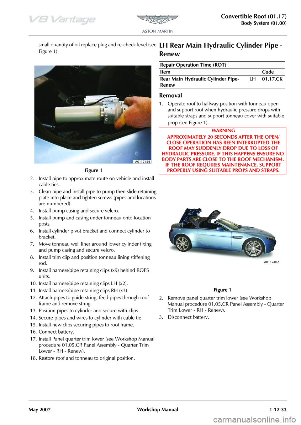
1. Operate roof to halfway position with tonneau open and support roof when hydraulic pressure drops with
suitable straps and support tonneau cover with suitable
prop (see Figure 1).
2. Remove panel quarter trim lower (see Workshop Manual procedure 01.05.CR Panel Assembly - Quarter
Trim Lower - RH - Renew).
3. Disconnect battery.
Figure 1
Repair Operation Time (ROT)
Page 181 of 947

Convertible Roof (01.17)
Body System (01.00)
May 2007 Workshop Manual 1-12-43
small quantity of oil replace plug and re-check level (see
Figure 1).
2. Install pipe to approximate route on vehicle and install cable ties.
3. Clean pipe and install pipe to pump. Slide retaining plate into place and tighten screws (pipes and locations
are numbered).
4. Install pump casing and secure velcro.
5. Install pump and casing under tonneau onto location posts.
6. Install cylinder pivot bracket and connect cylinder to bracket.
7. Move tonneau well liner ar ound lower cylinder fixing
and pump casing and secure velcro.
8. Install trim clip and position tonneau lining stiffening rod.
9. Attach pipes to guide stri ng, feed pipes through roof
frame and remove string.
10. Position pipes to cylinder and secure with clips.
11. Secure pipes and wires to cylinder with cable tie.
12. Install new clips securi ng pipes to roof frame.
13. Connect battery.
14. Install Panel quarter trim lower (see Workshop Manual procedure 01.05.CR Panel Assembly - Quarter Trim
Lower - RH - Renew).
15. Restore roof and tonneau to original position.
LH Front Hydraulic Cylinder Pipe -
Renew
Removal
1. Operate roof to halfway position with tonneau open then support roof when hydr aulic pressure drops with
suitable straps and support tonneau cover with suitable
prop (see Figure 1).
2. Remove wind deflector (see Workshop Manual
procedure 01.17.DA Wind Deflector - Renew).
3. Disconnect battery.
4. Remove lower cover (screw x1) (see Figure 2).
Figure 1
Repair Operation Time (ROT)
WA R N I N G
APPROXIMATELY 20 SECO NDS AFTER THE OPEN/
CLOSE OPERATION HAS BEEN INTERRUPTED THE ROOF MAY SUDDENLY DROP DUE TO LOSS OF
HYDRAULIC PRESSURE. IF THIS HAPPENS ENSURE NO
BODY PARTS ARE CLOSE TO THE ROOF MECHANISM. IF THE ROOF REQUIRES MAINTENANCE, SUPPORT PROPERLY USING SUITABLE PROPS AND STRAPS.
Figure 1
Figure 2
Page 188 of 947

Convertible Roof (01.17)
Body System (01.00)1-12-50 Workshop Manual May 2007
small quantity of oil replace plug and re-check level (see
Figure 1).
2. Install pipe to approximate route on vehicle and install cable ties.
3. Clean pipe and install pipe to pump then slide retaining plate into place and tighten screws (pipes and locations
are numbered).
4. Install pump casing and secure velcro.
5. Install pump and casing under tonneau onto location posts.
6. Install cylinder pivot bracket and connect cylinder to bracket.
7. Move tonneau well liner arou nd lower cylinder fixing
and pump casing and secure velcro.
8. Install trim clip and positi on tonneau lining stiffening
rod.
9. Install harness/pipe retaining clips (x9) behind ROPS units.
10. Install harness/pipe retaining clips LH (x2).
11. Install harness/pipe retaining clips RH (x3).
12. Attach pipes to guide stri ng, feed pipes through roof
frame and remove string.
13. Position pipes to cylinder and secure with clips.
14. Secure pipes and wires to cylinder with cable ties
15. Install pipe under keeper plate, install and tighten
screws.
16. Install new clips securing pipes to roof frame.
17. Install lower cover.
18. Connect battery.
19. Install Wind deflector (see Workshop Manual procedure 01.17.DA Wind Deflector - Renew).
20. Restore roof and tonneau to original positionRH Front Hydraulic Cylinder Pipe -
Renew
Removal
1. Operate roof to halfway position with tonneau open then support roof when hydraulic pressure drops with
suitable straps and support tonneau cover with suitable
prop (see Figure 1).
2. Remove wind deflector (see Workshop Manual procedure 01.17.DA Wind Deflector - Renew).
3. Disconnect battery.
Figure 1
Repair Operation Time (ROT)
ItemCode
Front Hydraulic Cylinder Pipe-Renew RH01.17.CQ
WAR NI NG
APPROXIMATELY 20 SECONDS AFTER THE OPEN/
CLOSE OPERATION HAS BEEN INTERRUPTED THE
ROOF MAY SUDDENLY DROP DUE TO LOSS OF
HYDRAULIC PRESSURE. IF THIS HAPPENS ENSURE NO
BODY PARTS ARE CLOSE TO THE ROOF MECHANISM.
IF THE ROOF REQUIRES MAINTENANCE, SUPPORT
PROPERLY USING SUITABLE PROPS AND STRAPS.
Figure 1
Page 194 of 947

Convertible Roof (01.17)
Body System (01.00)1-12-56 Workshop Manual May 2007
20. Remove cable ties and remove pipe from vehicle (see Figure 12).
Installation
1. Check oil level and top-up if necessary by removing reservoir end plug with pump in upright position, add
small quantity of oil replace plug and re-check level (see
Figure 1).
2. Install pipe to approximate route on vehicle and install cable ties.
3. Clean pipe and install pipe to pump then slide retaining plate into place and tighten screws (pipes and locations
are numbered).
4. Install pump casing and secure velcro.
5. Install pump and casing under tonneau onto location posts.
6. Install cylinder pivot bracket and connect cylinder to bracket. 7. Move tonneau well liner around lower cylinder fixing
and pump casing and secure velcro
8. Install trim clip and position tonneau lining stiffening rod.
9. Install harness/pipe retaining clips RH (x3).
10. Attach pipes to guide string, feed pipes through roof frame and remove string.
11. Position pipes to cylinder and secure with clips.
12. Secure pipes and wires to cylinder with cable ties
13. Install pipe under keeper plate, install and tighten screws.
14. Install new clips securi ng pipes to roof frame.
15. Install lower cover.
16. Connect battery.
17. Restore roof and tonneau to original position
RH/LH Rear Hydraulic Tonneau Cylinder
Pipe - Renew
Removal
1. Operate roof to halfway position with tonneau open then support roof when hydraulic pressure drops with
suitable straps and support tonneau cover with suitable
prop (see Figure 1).
Figure 12
Figure 1
Repair Operation Time (ROT)
ItemCode
Rear Hydraulic Tonneau Cylinder Pipe-
Renew LH
01.17.CS
Rear Hydraulic Tonneau Cylinder Pipe-
Renew RH
01.17.CV
WAR NI NG
APPROXIMATELY 20 SECONDS AFTER THE OPEN/
CLOSE OPERATION HAS BEEN INTERRUPTED THE
ROOF MAY SUDDENLY DROP DUE TO LOSS OF
HYDRAULIC PRESSURE. IF THIS HAPPENS ENSURE NO
BODY PARTS ARE CLOSE TO THE ROOF MECHANISM.
IF THE ROOF REQUIRES MAINTENANCE, SUPPORT
PROPERLY USING SUITABLE PROPS AND STRAPS.
Page 198 of 947

Convertible Roof (01.17)
Body System (01.00)1-12-60 Workshop Manual May 2007
small quantity of oil replace plug and re-check level (see
Figure 1).
2. Install pipe to approx imate route on vehicle.
3. Clean pipe and install pipe to pump then slide retaining plate into place and tighten screws (pipes and locations
are numbered).
4. Clean pipe, connect to cylinder and secure clip.
5. Install cable ties securing pipes and wires to cylinder.
6. Install harness/pipe retaining clips.
7. Position tonneau liner to body and install clips.
8. Install pump casing and secure velcro.
9. Install pump and casing under tonneau onto location posts.
10. Install cylinder pivot bracket and connect cylinder to bracket.
11. Move tonneau well liner arou nd lower cylinder fixing
and pump casing and secure velcro.
12. Install trim clip and positi on tonneau lining stiffening
rod.
13. Connect battery.
14. Restore roof and tonneau to original position
LH/RH Front Hydraulic Tonneau Cylinder
Pipe - Renew
Removal
1. Operate roof to halfway position with tonneau open then support roof when hydraulic pressure drops with suitable straps and support
tonneau cover with suitable
prop (see Figure 1).
2. Disconnect battery.
3. Remove trim clip and releas e tonneau lining stiffening
rod (see Figure 2).
4. Release velcro and move to nneau well liner aside to
e x p o s e l o w e r c y l i n d e r f i x i n g a n d m o t o r c a s i n g .
Figure 1
Repair Operation Time (ROT)
WAR NI NG
APPROXIMATELY 20 SECONDS AFTER THE OPEN/
CLOSE OPERATION HAS BEEN INTERRUPTED THE
ROOF MAY SUDDENLY DROP DUE TO LOSS OF
HYDRAULIC PRESSURE. IF THIS HAPPENS ENSURE NO
BODY PARTS ARE CLOSE TO THE ROOF MECHANISM.
IF THE ROOF REQUIRES MAINTENANCE, SUPPORT
PROPERLY USING SUITABLE PROPS AND STRAPS.
Figure 1
Figure 2
Page 201 of 947

Convertible Roof (01.17)
Body System (01.00)
May 2007 Workshop Manual 1-12-63
15. Remove harness/pipe retaining clips (x3) RH/LH (see Figure 11).
16. Remove pipe from vehicle.
Installation
1. Check oil level and top-up if necessary by removing
reservoir end plug with pump in upright position, add
small quantity of oil replace plug and re-check level (see
Figure 1).
2. Install pipe to approximate route on vehicle.
3. Clean pipe and install pipe to pump then slide retaining plate into place and tighten screws (pipes and locations
are numbered).
4. Clean pipe, connect to cylinder and secure clip.
5. Install cable ties securing pipes and wires to cylinder.
6. Install harness/pipe retaining clips.
7. Position tonneau liner to body and install clips.
8. Install pump casing and secure velcro. 9. Install pump and casing under tonneau onto location
posts.
10. Install cylinder pivot brack et and connect cylinder to
bracket.
11. Move tonneau well liner arou nd lower cylinder fixing
and pump casing and secure velcro.
12. Install trim clip and positi on tonneau lining stiffening
rod.
13. Connect battery.
14. Restore roof and tonneau to original position
Hydraulic Cylinder Valve to Pump Pipe -
Renew
Removal
1. Operate roof to halfway position with tonneau open then support roof when hydr aulic pressure drops with
suitable straps and support tonneau cover with suitable
prop (see Figure 1).
2. Disconnect battery.
Figure 11
Figure 1
Repair Operation Time (ROT)
Page 204 of 947

Convertible Roof (01.17)
Body System (01.00)1-12-66 Workshop Manual May 2007
14. Loosen (x6) screws on pump retaining plate (see Figure
10).
15. Slide retaining plate, discon nect pipe from pump (pipes
and locations are numbered).
16. Remove cable ties and remove pipe from vehicle (see Figure 11).
Installation
1. Check oil level and top-up if necessary by removing reservoir end plug with pump in upright position, add small quantity of oil replace plug and re-check level (see
Figure 1).
2. Install pipe to approximate route on vehicle and install
cable ties.
3. Clean pipe and install pipe to pump then slide retaining plate into place and tighten screws. (pipes and locations
are numbered).
4. Install motor casing and secure velcro.
5. Install motor and casing under tonneau onto location posts.
6. Install cylinder pivot bracket and connect cylinder to bracket.
7. Move tonneau well liner around lower cylinder fixing and motor casing and secure velcro
8. Position tonneau liner to body and install clips.
9. Install trim clip and position tonneau lining stiffening rod.
10. Clean pipe, connect pipe to valve, slide retaining plate
and tighten screw.
11. Install valve to support bracket, reposition bracket.
12. Install cable tie securing valve to bracket. Ensure no
pipes or wiring will foul roof mechanism.
13. Connect battery.
14. Restore roof and tonneau to original positionWind Deflector - Renew
Removal
1. Operate roof to halfway position with tonneau open then support roof when hydraulic pressure drops with
Figure 10
Figure 11
Figure 1
Repair Operation Time (ROT)
ItemCode
Wind Deflector-Renew 01.17.DA
Page 236 of 947
Engine Assembly (03.00)
Engine (03.00)3-0-4 Workshop Manual Issue 5, January 2010
Engine (03.00)
Engine Assembly (03.00)
Description
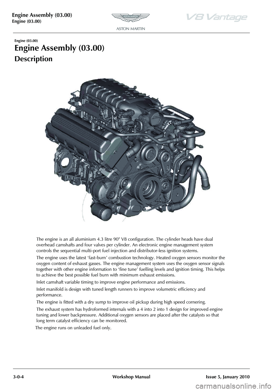
The engine is an all aluminium 4.3 litre 90° V8 configuration. The cylinder heads have dual
overhead camshafts and four valves per cylinder. An electronic engine management system
controls the sequential multi-port fuel injection and distributor-less ignition systems.
The engine uses the latest ‘fast-burn’ combustion technology. Heated oxygen sensors monitor the
oxygen content of exhaust gasses . The engine management system uses the oxygen sensor signals
together with other engine information to ‘fine tune ’ fuelling levels and ignition timing. This helps
to achieve the best possible fuel bur n with minimum exhaust emissions.
Inlet camshaft variable timing to impr ove engine performance and emissions.
Inlet manifold is design with tuned length runners to improve volumetric efficiency and
performance.
The engine is fitted with a dry sump to improv e oil pickup during high speed cornering.
The exhaust system has hydroforme d internals with a 4 into 2 into 1 design for improved engine
tuning and lower backpressure. Additional oxygen sensors are placed after the catalysts so that
long term catalyst efficiency can be monitored.
The engine runs on unleaded fuel only.
Page 253 of 947
Engine Structure (03.01)
Issue 4, November 2008Workshop Manual 3-1-5
Maintenance
Upper Intake Manifold Assembly (LHD) -
Renew
Removal
1. Depressurise fuel rail (see Workshop Manual procedure
10.01.EK Fuel System - Depressurise).
2. Coolant drain (see Workshop Manual procedure 03.03.AD Coolant - Drain and Refill).
3. Remove cross brace (bolts x4).
Removal RH Side
4. Remove coil cover.
5. Disconnect breather hose (quick fit) move aside.
6. Release harness fir tree clips (x3) from cylinder head and move aside.
7. Remove fuse box bracket fixings (bolt and nut) (allows movement).
8. Remove ECM (see Workshop Manual procedure 03.14.BB Engine Contro l Module - RH - Renew).
9. Remove battery lead (1x nut and rubber cover) from fuse box (2x leads).
10. Remove multiplugs (x10) from fusebox.
11. Remove earth terminal (x1 nut and rubber cover) from fusebox.
12. Remove fuse box from bracket (bolt x2).
13. Release harness fir tree clips (x3) from engine bracket.
14. Feed harness from inner wing and over engine.
15. Remove purge pipe P-clip (bolt x1) and move pipe aside.
16. Remove harness bracket from engine (bolts x2, nut x1).
17. Release fuel feed hose from rail (clip x1) and move aside.
18. Disconnect heater hose from pipe (quick fit).
19. Release heater hose (clips x2) and EGR vacuum line (clips x2) from bracket.
20. Release harness from coolant pipe bracket (fir tree x3).
21. Disconnect EGR (x1), fuel ra il pressure sensor (x1) and
injector (x4) multiplu gs, move harness aside. 22. Remove coolant pipe bracket (nuts x2 and bolts x2).
23. Disconnect EGR vacuum pipe from sensor and
manifold, move aside.
Removal LH Side
24. Remove corner cross brace.
25. Remove coil cover.
26. Disconnect breather hoses from cam cover (x2) for access.
27. Disconnect purge line from manifold (quickfit) and
support clip for access.
28. Disconnect heater hose from pipe (quick fit).
29. Release heater hose (x2) and throttle body hose (x2) from support bracket.
30. Remove booster hose from manifold and support clip.
31. Remove harness support bracket (bolt x1, nut x2) release harness clips (fir tree x3).
32. Release pipe support bracket (nuts x2, bolts x2) move aside.
33. Disconnect injector multiplugs (x4).
34. Unclip injector harness from cam cover (x2).
35. Disconnect IAT multiplug.
36. Disconnect breather hose from manifold (quickfit).
Removal Manifold from Vehicle
37. Disconnect manifold heating hoses (x2).
38. Disconnect throttle body multiplug and harness clip.
39. Disconnect breather pipe quickfits (x2) from air cleaner duct.
40. Disconnect air cleaner duct (clip x1).
41. Disconnect EGR vacuum hose.
42. Disconnect EGR pipe union and tie aside.
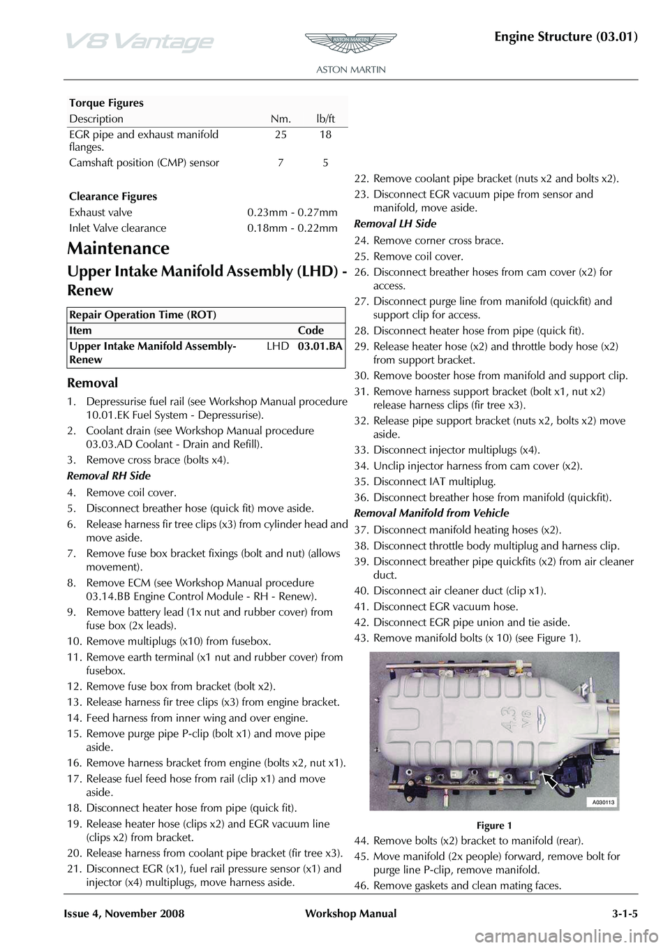
43. Remove manifold bolts (x 10) (see Figure 1).
Figure 1
44. Remove bolts (x2) bracket to manifold (rear).
45. Move manifold (2x people) forward, remove bolt for purge line P-clip, remove manifold.
46. Remove gaskets and clean mating faces.
EGR pipe and exhaust manifold
flanges.
25 18
Camshaft position (CMP) sensor 7 5
Torque Figures
DescriptionNm.lb/ft
Clearance Figures
Exhaust valve0.23mm - 0.27mm
Inlet Valve clearance 0.18mm - 0.22mm
Repair Operation Time (ROT)
A030113