AUDI A4 1996 B5 / 1.G 01W Transmission Selector Mechanism Workshop Manual
Manufacturer: AUDI, Model Year: 1996,
Model line: A4,
Model: AUDI A4 1996 B5 / 1.G
Pages: 10, PDF Size: 0.27 MB
AUDI A4 1996 B5 / 1.G 01W Transmission Selector Mechanism Workshop Manual
A4 1996 B5 / 1.G
AUDI
AUDI
https://www.carmanualsonline.info/img/6/1279/w960_1279-0.png
AUDI A4 1996 B5 / 1.G 01W Transmission Selector Mechanism Workshop Manual
Trending: light, relay, transmission oil, oil, lock
Page 1 of 10
34-62
Transmission selector
mechanism, disassembling
and assembling
Special tools and equipment
VW295 needle bearing drift
VW295A needle bearing drift
VW401 thrust plate
VW423 sleeve
VW472/2 spacer sleeve
VW771 peening tool
Kukko 21/4 extractor
Pa
ge 1 of 10 Transmission selector mechanism, disassemblin
g and assemblin
g
11/19/2002 htt
p://127.0.0.1:8080/audi/servlet/Dis
play?action=Goto&t
yp
e=re
pair&id=AUDI.B5.TM01.34.5
Page 2 of 10
34-63
Note:
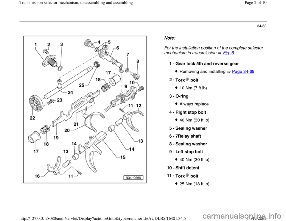
For the installation position of the complete selector
mechanism in transmission Fig. 6
.
1 -
Gear lock 5th and reverse gear
Removing and installing Page 34
-69
2 -
Torx bolt
10 Nm (7 ft lb)
3 -
O-ring Always replace
4 -
Right stop bolt 40 Nm (30 ft lb)
5 -
Sealing washer
6 -
7Relay shaft
8 -
Sealing washer
9 -
Left stop bolt 40 Nm (30 ft lb)
10 -
Shift detent
11 -
Torx bolt 25 Nm (18 ft lb)
Pa
ge 2 of 10 Transmission selector mechanism, disassemblin
g and assemblin
g
11/19/2002 htt
p://127.0.0.1:8080/audi/servlet/Dis
play?action=Goto&t
yp
e=re
pair&id=AUDI.B5.TM01.34.5
Page 3 of 10
34-64
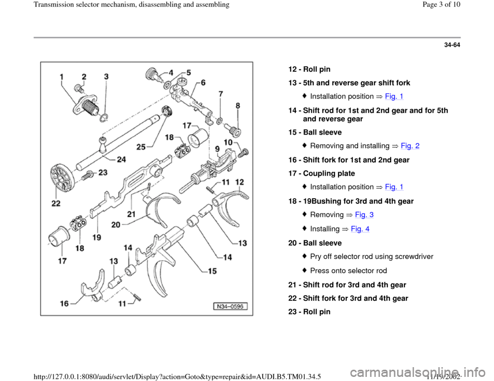
12 -
Roll pin
13 -
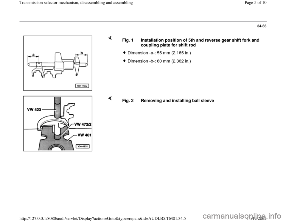
5th and reverse gear shift fork
Installation position Fig. 1
14 -
Shift rod for 1st and 2nd gear and for 5th
and reverse gear
15 -
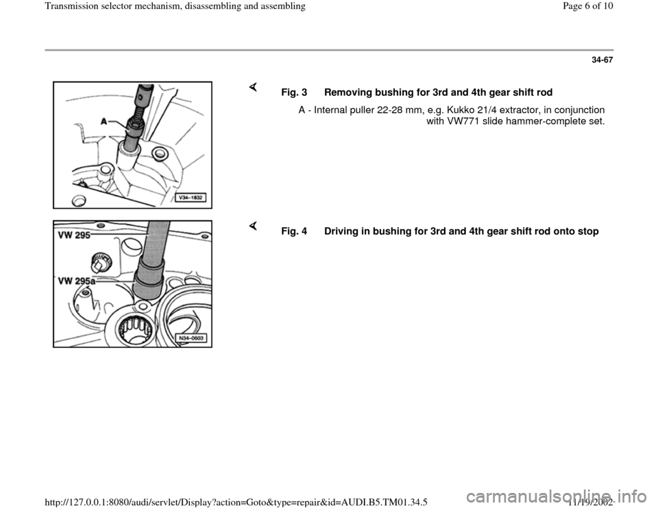
Ball sleeve
Removing and installing Fig. 2
16 -
Shift fork for 1st and 2nd gear
17 -
Coupling plate
Installation position Fig. 1
18 -
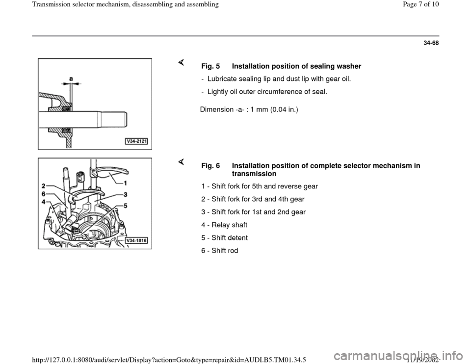
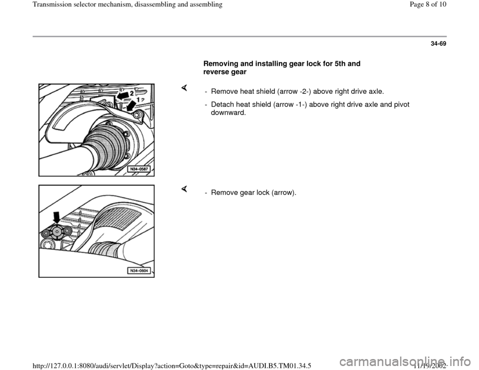
19Bushing for 3rd and 4th gear
Removing Fig. 3Installing Fig. 4
20 -
Ball sleeve
Pry off selector rod using screwdriverPress onto selector rod
21 -
Shift rod for 3rd and 4th gear
22 -
Shift fork for 3rd and 4th gear
23 -
Roll pin
Pa
ge 3 of 10 Transmission selector mechanism, disassemblin
g and assemblin
g
11/19/2002 htt
p://127.0.0.1:8080/audi/servlet/Dis
play?action=Goto&t
yp
e=re
pair&id=AUDI.B5.TM01.34.5
Page 4 of 10
34-65
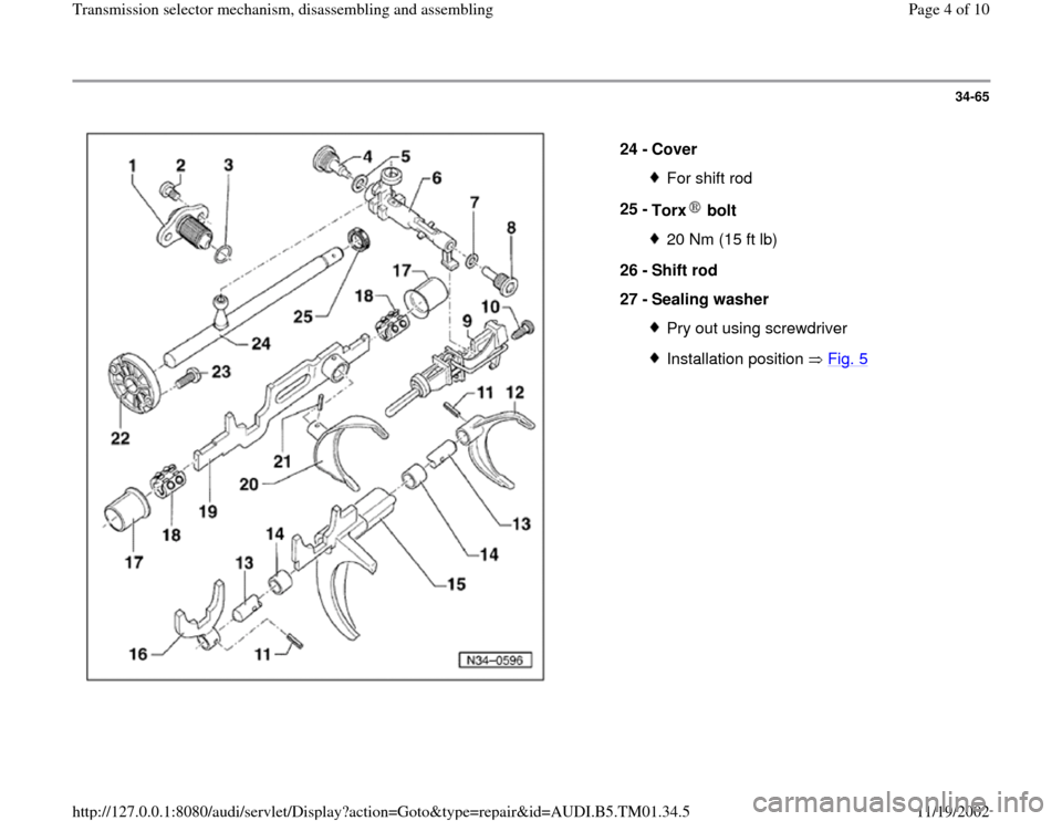
24 -
Cover
For shift rod
25 -
Torx bolt 20 Nm (15 ft lb)
26 -
Shift rod
27 -
Sealing washer Pry out using screwdriverInstallation position Fig. 5
Pa
ge 4 of 10 Transmission selector mechanism, disassemblin
g and assemblin
g
11/19/2002 htt
p://127.0.0.1:8080/audi/servlet/Dis
play?action=Goto&t
yp
e=re
pair&id=AUDI.B5.TM01.34.5
Page 5 of 10
34-66
Fig. 1 Installation position of 5th and reverse gear shift fork and
coupling plate for shift rod
Dimension -a-: 55 mm (2.165 in.)Dimension -b-: 60 mm (2.362 in.)
Fig. 2 Removing and installing ball sleeve
Pa
ge 5 of 10 Transmission selector mechanism, disassemblin
g and assemblin
g
11/19/2002 htt
p://127.0.0.1:8080/audi/servlet/Dis
play?action=Goto&t
yp
e=re
pair&id=AUDI.B5.TM01.34.5
Page 6 of 10
34-67
Fig. 3 Removing bushing for 3rd and 4th gear shift rod
A - Internal puller 22-28 mm, e.g. Kukko 21/4 extractor, in conjunction
with VW771 slide hammer-complete set.
Fig. 4 Driving in bushing for 3rd and 4th gear shift rod onto stop
Pa
ge 6 of 10 Transmission selector mechanism, disassemblin
g and assemblin
g
11/19/2002 htt
p://127.0.0.1:8080/audi/servlet/Dis
play?action=Goto&t
yp
e=re
pair&id=AUDI.B5.TM01.34.5
Page 7 of 10
34-68
Dimension -a- : 1 mm (0.04 in.) Fig. 5 Installation position of sealing washer
- Lubricate sealing lip and dust lip with gear oil.
- Lightly oil outer circumference of seal.
Fig. 6 Installation position of complete selector mechanism in
transmission
1 - Shift fork for 5th and reverse gear
2 - Shift fork for 3rd and 4th gear
3 - Shift fork for 1st and 2nd gear
4 - Relay shaft
5 - Shift detent
6 - Shift rod
Pa
ge 7 of 10 Transmission selector mechanism, disassemblin
g and assemblin
g
11/19/2002 htt
p://127.0.0.1:8080/audi/servlet/Dis
play?action=Goto&t
yp
e=re
pair&id=AUDI.B5.TM01.34.5
Page 8 of 10
34-69
Removing and installing gear lock for 5th and
reverse gear
- Remove heat shield (arrow -2-) above right drive axle.
- Detach heat shield (arrow -1-) above right drive axle and pivot
downward.
- Remove gear lock (arrow).
Pa
ge 8 of 10 Transmission selector mechanism, disassemblin
g and assemblin
g
11/19/2002 htt
p://127.0.0.1:8080/audi/servlet/Dis
play?action=Goto&t
yp
e=re
pair&id=AUDI.B5.TM01.34.5
Page 9 of 10
34-70
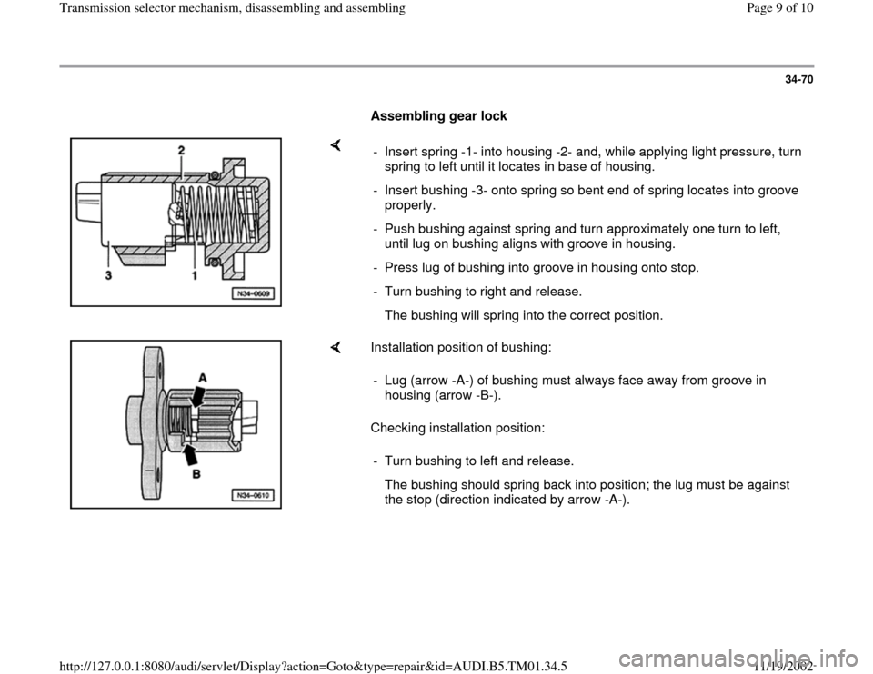
Assembling gear lock
- Insert spring -1- into housing -2- and, while applying light pressure, turn
spring to left until it locates in base of housing.
- Insert bushing -3- onto spring so bent end of spring locates into groove
properly.
- Push bushing against spring and turn approximately one turn to left,
until lug on bushing aligns with groove in housing.
- Press lug of bushing into groove in housing onto stop.
- Turn bushing to right and release.
The bushing will spring into the correct position.
Installation position of bushing:
Checking installation position: - Lug (arrow -A-) of bushing must always face away from groove in
housing (arrow -B-).
- Turn bushing to left and release.
The bushing should spring back into position; the lug must be against
the stop (direction indicated by arrow -A-).
Pa
ge 9 of 10 Transmission selector mechanism, disassemblin
g and assemblin
g
11/19/2002 htt
p://127.0.0.1:8080/audi/servlet/Dis
play?action=Goto&t
yp
e=re
pair&id=AUDI.B5.TM01.34.5
Page 10 of 10
34-71
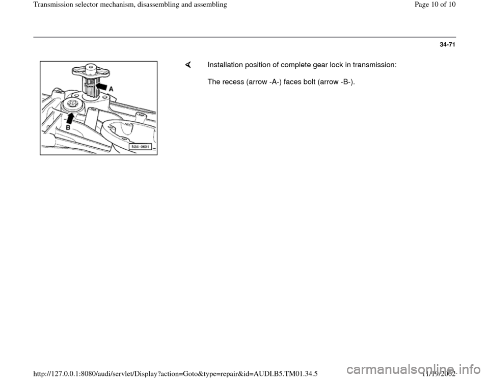
Installation position of complete gear lock in transmission:
The recess (arrow -A-) faces bolt (arrow -B-).
Pa
ge 10 of 10 Transmission selector mechanism, disassemblin
g and assemblin
g
11/19/2002 htt
p://127.0.0.1:8080/audi/servlet/Dis
play?action=Goto&t
yp
e=re
pair&id=AUDI.B5.TM01.34.5
Trending: transmission oil, oil, relay, light, lock
